DOI:
10.1039/C6RA20389B
(Paper)
RSC Adv., 2016,
6, 100546-100553
MgO-templated mesoporous carbons using a pitch-based thermosetting carbon precursor
Received
12th August 2016
, Accepted 11th October 2016
First published on 12th October 2016
Abstract
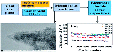
A pitch-based thermosetting amphiphilic carbonaceous material (CP-A5) was converted to mesoporous carbons (MCs) by an MgO-templated method. The yields of MCs were competitive, up to 17%. Temperature-programmed desorption (TPD), thermogravimetric analysis (TG), high-resolution transmission electron microscopy (HRTEM) and N2 adsorption–desorption were applied to characterize the precursors and MgO-templated MCs. Compared with some published template carbons from thermoplastic materials, less collapse was observed due to the thermosetting property of the carbon precursor. MC73 (MgO/CP-A5 at 7/3 mass ratio) had a surface area of 1991 m2 g−1 and interconnected micropores/mesopores, which endowed it with outstanding electrochemical performance in 1 M TEABF4/PC organic electrolyte, namely, a gravimetric specific capacitance of 90.8 F g−1 at 0.05 A g−1 and a capacitance retention of 91.3% after 10
000 cycles at 1 A g−1. MC73 is a promising electrode material candidate for energy storage by electrical double layer capacitors. Considering their competitive carbon yields as well as the cyclic ability of MgO, development of MCs from coal tar pitch by an MgO-templated method is feasible and promising, particularly in terms of the upgrade of heavy residues in coal-related industry.
1. Introduction
Heavy derivatives from petroleum or coal-related industrial processing (pitch, petroleum coke, needle coke and so on) consist of various stable polycyclic aromatic hydrocarbons or rigid segments of six-carbon rings, which determine their unique superiority as carbon precursors because of their structural analogy and high carbon elemental content. Compared to their traditional utilization as fuel, developing carbon materials for energy storage is feasible and an economically upgraded strategy.
Electrical double layer capacitors (EDLCs) have attracted much attention due to their high power density, superior reversibility and long cycle life.1–3 EDLCs store electrical energy by forming an electric double layer at the electrode/electrolyte interface of porous electrode materials.4,5 Therefore, the performance is greatly dependent on the highly developed surface area and reasonable pore distribution of the electrode materials that are accessible for electrolyte ion transport in the pore channels.6
Mesoporous carbons are one of the most commonly used electrode materials for EDLCs because of their appropriate specific surface area, abundant mesoporous structure, and reasonable pore size for quick ion diffusion.6 Mesoporous carbons with different pore sizes and morphologies have been prepared by silicas7,8 as template. However, template removal in this process requires the employment of corrosive hydrofluoric acid which makes large-scale production difficult. An industrialized MgO-templated method proposed by M. Inagaki et al.,9–13 which needs only one step carbonization without any stabilization and activation processes, has stimulated extensive interest.14–16 In addition to, the MgO template has many advantages, such as stable structure and composition, recyclability, and easy dissolution into diluted acidic solution.17 Numerous mesoporous carbons by the MgO-templated method have shown good electrochemical performance in EDLCs. Fernández et al.13 reported the synthesis of mesoporous carbons with a pore size of 2–15 nm, using magnesium citrate as an MgO template precursor and poly(vinyl alcohol) as a carbon precursor. Such mesoporous carbons showed electrochemical performance with a specific capacitance of 180 F g−1 at 1 mA cm−2 in aqueous 2 M H2SO4 electrolyte and approximately 100 F g−1 in 1 M (C2H5)4NBF4 in acetonitrile. Morishita et al.12 also obtained mesoporous carbons with magnesium acetate and poly(vinyl alcohol) as precursors, and the electrodes made from these MCs showed a high EDLC capacitance. Kado et al.18,19 used trimagnesium dicitrate nonahydrate as both template and carbon precursor, and the resulting mesoporous carbons exhibited large capacitances and excellent rate performances for EDLCs in 1 M (C2H5)4NBF4 in propylene carbonate. However, carbon yields of mesoporous carbons by the method can be further improved.
In our previous study, we determined amphiphilic carbonaceous materials obtained from coal tar pitch (CP) and green needle coke to be thermosetting and having abundant functional groups (–COOH, –OH, –SO3H, –NO2).20,21 The obtained amphiphilic carbonaceous materials have many rigid segments as they come from a mixture of polycyclic aromatic hydrocarbons. X. Zhang22 found that coal tar pitch-based amphiphilic carbonaceous material (CP-A5) with negatively charged centers could disperse in distilled water. The negatively charged centers can attract Mn2+ ions, so it is reasonable to infer that they can also attract Mg2+ in the same way. In this paper, magnesium citrate (MgCi) as a template and coal tar pitch-based amphiphilic carbonaceous material as a carbonaceous candidate were together used to prepare mesoporous carbons (MCs) for EDLCs. Different template dosages were applied. The yields, the pore structure and electrochemical performances of mesoporous carbons were evaluated. Particular attention was given to elucidate the relationship between template dosages and energy storage performances.
2. Experiment
2.1. Preparations of mesoporous carbons
Coal tar pitch (CP) was provided by Tianjin Tie-zhong Coal-Chemical Co. in China. Magnesium citrate (MgCi) was used as analytical grade pure and purchased from Tianjin Guangfu Fine Chemical Research Institute. The detailed preparation process of coal tar pitch-based amphiphilic carbonaceous material (CP-A5) was described by J. Wang et al.21
Preparation of mesoporous carbons samples included three steps. Firstly, 2 g CP-A5 was completely dissolved in water. MgCi was dissolved in CP-A5 aqueous solution with the mass ratio varying from 2/8 to 8/2 (MgO/CP-A5 mass ratio). The obtained mixture was dried at 80 °C. Secondly, the dried mixture was grinded adequately in an agate mortar, and carbonized by programmed heating to 900 °C in a tubular furnace under N2 atmosphere for 1 h. Finally, the MgO template in the product was removed using 2 M HCl solution at 80 °C. The obtained mesoporous carbons were washed with distilled water several times until the pH of the solution reached 7. The mesoporous carbons prepared were named MCab, where ‘ab’ was the MgO/CP-A5 mass ratio. For example, the mesoporous carbon prepared from the mixture MgO/CP-A5 at 2/8 mass ratio was denoted MC28. The mixture of CP-A5 and MgCi after heat-treatment at 900 °C was named carbon-coated MgO. The yields of the carbon-coated MgO (YMgO/C) were calculated from the mass ratio of carbon-coated MgO to the mixture of CP-A5 and MgCi. The yields of MCs (YC) were calculated from the mass of the MCs divided by the mass of the mixture of CP-A5 and MgCi.
2.2. Structural characterization
The surface chemistry of CP-A5 was analyzed by temperature-programmed desorption (TPD). TPD measurement was conducted to quantify the CO and CO2 released during heating under N2 atmosphere. Thermogravimetric (TG) analysis was performed on CP-A5, MgCi and the mixture of MgO/CP-A5 at 2/8 mass ratio using a thermogravimetric analyzer (TA Instruments TA-50) under N2 atmosphere at 5 °C min−1. The X-ray diffraction (XRD) patterns were obtained with a Rigaku D/max 2500 v/PC system using Cu Kα radiation (λ = 1.5406 Å). The nanostructure of carbons was examined with a transmission electron microscope (HRTEM, Philips Tecnai G2F-20).
The specific surface areas and the pore structures of the samples were examined by N2 adsorption measurements with a gas adsorption analyzer at 77 K (Micromeritics Instrument Corporation Tristar 3000). Before the measurements, the samples were degassed at 300 °C for 5 h under N2. BET surface area (SBET) was calculated from the isotherm in the relative pressure range 0.05–0.30. The micropore volume (Vmicro) and the total pore volume (Vtotal) were calculated from the amount of N2 adsorbed at a relative pressure (P/P0) of 0.1 and 0.95, respectively, using the t-plot method. Moreover, total pore area (Stotal) and micropore area (Smicro) were also determined by the t-plot method, and mesopore area (Smeso) was calculated as a balance between Stotal and Smicro. Pore size distributions were determined by the Barrett Joyner Halenda (BJH) model.
2.3. Electrochemical characterization
The electrodes for the EDLCs were prepared by mixing the MCs, carbon black and polytetrafluoroethylene (PTFE) in the mass ratio of 80
:
10
:
10. The mixture was dispersed in ethanol and compressed by a roll squeezer into a thin sheet that was 80–100 μm in thickness. Disks with a diameter of 13 mm were punched out from the sheet as test electrodes and were then dried at 100 °C for 12 h. Conductive aluminum foil was used as current collector. The electrochemical behaviors were investigated in 1 M tetraethylammonium tetrafluoroborate salt solution in propylene carbonate (1 M TEABF4/PC).
The electrochemical performances of the MCs electrode materials were measured by cyclic voltammetry (CV), electrochemical impedance spectroscopy (EIS) tests and galvanostatic charge/discharge cycles. CV and EIS were performed on a potentiostat/galvanostat (PARSTAT 2273, Princeton Applied Research, USA). The potential range of CV was 0–2.7 V at a voltage scan rate of 20–200 mV s−1. Nyquist plots were recorded at frequencies ranging from 100 kHz to 10 mHz. The galvanostatic charge/discharge tests were conducted at different current densities using an Arbin battery test instrument with a potential window of 0–2.7 V. The current densities employed for the measurement of capacitance were from 0.05 A g−1 to 10 A g−1.
Traditionally, based on the results of charge/discharge tests, the gravimetric capacitance (Cg) and volumetric capacitance (Cv) of a single electrode was calculated according to the discharge part of galvanostatic charge/discharge curves. In the following formula,
|
Cg (F g−1) = 2 × I/m(ΔV/Δt)
| (1) |
|
Cv (F cm−3) = Cg × delectrode
| (2) |
I refers to the discharge current,
t is the discharge time,
V is the value of voltage,
m is the mass of resultant carbon on the single electrode and Δ
V/Δ
t is calculated from the slope of the discharge part of the galvanostatic charge/discharge curves.
delectrode is the compact density of electrode. However, the initial portion of a discharge curve exhibits an ohmic-drop due to internal resistance, so the above formula overestimates
Cg. A practical calculation method was put forward by Meryl D. Stoller and Rodney S. Ruoff.
23 The recommended method is to use two data points from the discharge curve:
|
dV/dt = (Vmax − V1/2max)/(t1/2max − tmax)
| (3) |
where
Vmax and
V1/2max are the maximum and half maximum discharge voltage, respectively, while
tmax and
t1/2max are the time referenced to the maximum and half maximum discharge voltage, respectively. Rate performance of the EDLCs was evaluated by the ratio of the capacitance measured at 10 A g
−1 against that at 0.05 A g
−1,
C10/
C0.05. All electrochemical measurements were carried out at room temperature.
3. Results and discussion
3.1. Yields of carbon-coated MgO and MCs
For practical industrial applications, the yields of obtained mesoporous carbons are significant. When CP-A5 was used as carbon precursor, the yields of carbon-coated MgO were over 30% and MCs were above 17% (Table 1). Such high yields, 30% in particular, are very competitive compared to those obtained using thermoplastic precursors.16 The C/H atom ratio of CP-A5 is 2.04 at%, compared to 0.50 at% for poly(vinyl alcohol) and 1.4 at% for anthracene. Thus, the C/H atom ratios indicate that CP-A5 contains the larger proportion of rigid segments that are structural analogous to that of carbon materials. Therefore, the high carbon yields are reasonable, and comparable to other pitch-based carbon.24 The yields of carbon-coated MgO from different pitch-based MgO-templated carbons14 are listed in Table 1.
Table 1 The yields of carbon-coated MgO and mesospores carbons
Precursors |
Mass ratio |
YMgO/C (mass%) |
YC (mass%) |
Magnesium citrate/CP-A5 |
2/8 |
35 |
21 |
5/5 |
33 |
19 |
6/4 |
32 |
19 |
7/3 |
31 |
18 |
8/2 |
31 |
17 |
Magnesium citrate/coal tar pitch14 |
2/8 |
65 |
— |
5/5 |
42 |
— |
7/3 |
32 |
— |
8/2 |
30 |
— |
Magnesium acetate/coal tar pitch14 |
2/8 |
63 |
— |
5/5 |
23 |
— |
7/3 |
8 |
— |
8/2 |
4 |
— |
3.2. Characterization of precursors and the mesoporous carbons
TPD combined with TG provides detailed information about surface functional groups and related pyrolysis characteristics of CP-A5 in an inert atmosphere. Table 2 summarized the surface functional groups on CP-A5 resolved from TPD spectra shown in Fig. 1a and b.25 CP-A5 has many edge groups such as carboxyl (1741.1 μmol mg−1) and anhydride (2118.1 μmol mg−1) that promote its hydrophilic nature, helping homogeneous mixing with MgCi in aqueous solution, similar to homogeneous KOH activation in nanoporous carbon synthesis.16 These functional groups could decompose in the carbonization process. Below 130 °C, CP-A5 loses H2O up to 2.3% in mass (Fig. 1c). Afterwards, CP-A5 loses 43% in mass in the intermediate temperature span from 130 to 700 °C owing to anhydride, carboxylic and phenol decomposition. Above 700 °C mass loss becomes gradual and the residual is 51%, which contributes to carbon yield. TPD also shows that few surface groups are retained after 800 °C. Thermogravimetric curves of MgCi and the mixture of MgO/CP-A5 at 2/8 mass ratio were shown in Fig. 1d. The MgCi curve shows three mass-loss peaks corresponding to different temperature ranges between 100–200 °C, 300–400 °C, and 400–600 °C. The first peak indicates the removal of crystal water, the second one is the decomposition of MgCi to Mg carbonate, and the third one is the formation of MgO.26 The MgO formation occurs after the initiation of pyrolysis of CP-A5. Therefore, MgCi should be surrounded by the carbonaceous materials of partially pyrolyzed CP-A5 before its decomposition. The decomposition of MgCi is known to not only give nano-sized MgO particles but also citric acid, which can provide a little carbon. In this complex, MgO particles are surrounded by carbon from CP-A5 and the decomposition product of citric acid. The MgO surrounded by carbon can remain nano-sized at high temperatures.
Table 2 CO and CO2 amounts obtained by integration of TPD peak area in CP-A5
CO |
CO2 |
Func. group |
Peak location/°C |
Amount/(μmol mg−1) |
Func. group |
Peak location/°C |
Amount/(μmol mg−1) |
Anhydride |
352.85 |
188.9 |
Carboxylic |
190.45 |
986.6 |
423.75 |
880.0 |
243.75 |
754.5 |
Phenol |
514.75 |
504.7 |
Anhydride |
362.85 |
1049.2 |
 |
| Fig. 1 TPD spectra of CP-A5 under N2 atmosphere to different extents, CO2 evolution (a) and CO evolution (b); thermogravimetric curves for CP-A5 (c) and for MgCi and the mixture with an MgO/CP-A5 mass ratio of 2/8 (d) under N2 atmosphere. | |
Highly crystalline MgO has very strong and sharp diffraction peaks in the XRD pattern of carbon-coated MgO at 7/3 mass ratio (Fig. 2a). From Fig. 2b, it can be observed that amorphous carbon has two wide peaks at 23° and 43° that are in accordance with the 002 peak and the 100 peak, respectively. Additionally, the 002 peak of carbon formed from CP-A5 can be observed in Fig. 2a. Its weak 100 peak overlaps the stronger 200 peak of MgO, so it is difficult to detect in the XRD pattern. As MgO is dissolved by HCl, there are no MgO diffraction peaks found in the XRD pattern (Fig. 2b), and the overlapped 100 peak for amorphous carbon appears.
 |
| Fig. 2 X-ray diffraction patterns of carbon-coated MgO (a) and mesoporous carbons (b); TEM images of carbon-coated MgO (c) and mesoporous carbons (d) with MgO/CP-A5 at 7/3 mass ratio. | |
HRTEM images were shown in Fig. 2c and d. Notably, the MgO particles, like “small islands,” disperse uniformly in the carbon matrix (Fig. 2c). The “small islands” are round and independent of each other because they are surrounded by carbon. After the dissolution of the “small islands”, holes are left (Fig. 2d). Some collapses can be found, but the collapses are negligible compared to the thermoplastic materials. Therefore, thermosetting carbon materials together with an MgO-template method can fully show the advantage of the template method.
3.3. Pore structure of MCs
To investigate the effect of the template agent to precursor ratio on the porosity and the specific surface area, the N2 adsorption/desorption isotherms and pore size distributions of the resultant carbons were determined (Fig. 3a and b). All of the samples exhibit type-IV isotherms with hysteresis loops caused by capillary condensation in the intermediate relative pressure range, indicating the existence of rich mesopores. The adsorption capacity of the MCs increases with increasing MgO/CP-A5 mass ratio and reaches a maximum value at 7/3 mass ratio. The pore size distributions of MCs are between 2 nm and 5 nm and no significant changes are observed with increasing MgO/CP-A5 mass ratio. These mesopores derive from the formation of MgO nanoparticles and/or the stacking of carbon flakes. In addition, all of the isotherms reveal considerable adsorption at relatively low pressure, which indicates that some micropores are present. This is because the surface functional groups of CP-A5 are thermally instable and can decompose and release gases such as CO2, H2O and thus create micropores during the process of carbonization. Additionally, citric acid from MgCi can contribute to the formation of micropores. The MCs with microporous/mesoporous structures can provide abundant adsorption sites and a diffusion channel for the electrolyte ions. It can be observed from Table 3 that the pore structure parameters increase with increasing MgO/CP-A5 mass ratio and reach a maximum at 7/3. However, when it increases to 8/2, the pore parameters show little change. Therefore, MC73 has optimal pore structure parameters. Pore parameters of the reported pitch-based mesoporous carbons14 were shown in Table 4. In the literature, different MgO precursors resulted in different pore parameters. When magnesium citrate was used as an MgO precursor, the average pore diameter was 5 nm, larger than that of CP-A5 resultant carbons. This is ascribed to the different mixing methods and the different carbon precursor. CP-A5 is hydrophilic and therefore it can form a uniform mixture with magnesium citrate. This leads to mesoporous carbons from CP-A5 with smaller average pore diameters.
 |
| Fig. 3 Nitrogen adsorption–desorption isotherms (a) and pore size distribution of mesoporous carbons (b). | |
Table 3 Pore parameters of mesoporous carbons from CP-A5
Sample |
SBET (m2 g−1) |
Smic (m2 g−1) |
Smes (m2 g−1) |
Vtot (cm3 g−1) |
Vmic (cm3 g−1) |
Vmes (cm3 g−1) |
The average pore diameters (nm) |
MC28 |
946 |
302 |
644 |
0.57 |
0.07 |
0.50 |
2.8 |
MC55 |
1393 |
373 |
1020 |
0.84 |
0.08 |
0.76 |
MC64 |
1788 |
457 |
1331 |
1.06 |
0.10 |
0.96 |
MC73 |
1991 |
497 |
1494 |
1.20 |
0.13 |
1.07 |
MC82 |
1938 |
448 |
1490 |
1.13 |
0.12 |
1.01 |
Table 4 Pore parameters of mesoporous carbons from coal tar pitch14
Precursors |
Mass ratio |
SBET (m2 g−1) |
The average pore diameters (nm) |
Magnesium citrate/coal tar pitch |
2/8 |
310 |
5 |
5/5 |
765 |
7/3 |
1184 |
8/2 |
1300 |
Magnesium acetate/coal tar pitch |
2/8 |
130 |
12 |
5/5 |
490 |
7/3 |
1187 |
8/2 |
810 |
To objectively present the porous structure, particularly the connectivity of pores, TEM images and inverse fast Fourier transform (IFFT) images of MC73 were shown in Fig. 4. The specific frequency regions in reciprocal space were chosen by ring-shaped mask patterns. After IFFT, images corresponding to a pore size of 1–2 nm and 2–5 nm could be obtained. The real space images were then transformed to binary pictures to observe the pore shapes more clearly. MC73 is amorphous and abundant mesopores as well as micropores were created during the carbonization process. From the transformed images, it is clear that both micropores (1–2 nm) and mesopores (2–5 nm) are well interconnected.
 |
| Fig. 4 TEM image of the MC73 sample (a); (b, e) the IFFT image after filtering the power spectrum from (a); (c) the filter pattern corresponding to a pore size of 1–2 nm; (d) the binary image of (b); (f) the filter pattern corresponding to the pore size of 2–5 nm and (g) the binary image of (f). | |
3.4. Electrochemical performances of MCs electrodes
Inspired by the structural advantages, the materials were evaluated by CV and galvanostatic charge/discharge tests in 1 M TEABF4/PC organic electrolyte. The CV curves of all samples are rectangular-like without any redox peaks at a scan rate of 5 mV s−1, as shown in Fig. 5a. This indicates that all MCs have pure capacitive behaviors.27 CV curves for MC73 with various scan rates changing from 5 to 200 mV s−1 were shown in Fig. 5b. With the increase of scan rates, the CV curves become a little distorted but still maintain a rectangular-shaped characteristic even at 200 mV s−1, illustrating an excellent rate performance. This suggests that the electrolyte ions have good accessibility to the inner-pores of MCs because of the existence of suitable mesopores and micropores (Fig. 3), endowing the MCs with excellent electrochemical performance.28
 |
| Fig. 5 Electrochemical behaviors of mesoporous carbons using 1 M TEABF4/PC organic electrolyte, (a) CV curves obtained for mesoporous carbons at a scan rate of 5 mV s−1, (b) CV curves of MC73 measured at different scan rates, (c) gravimetric specific capacitance at different current densities, (d) galvanostatic charge–discharge curves, (e) volumetric specific capacitance at different current densities, (f) cycle performances at a current density of 1 A g−1, (g) electrode density of MCs, (h) Nyquist plots in the frequency range of 10 mHz to 100 kHz for the MCs electrodes. | |
The gravimetric specific capacitance and galvanostatic charge/discharge curves of MCs were shown in Fig. 5c and d. With the increasing MgO/CP-A5 mass ratio, the capacitance increases gradually and reaches a maximum value at 7/3. The MC73 processes a capacitance of 90.8 F g−1 at a current density of 0.05 A g−1 and the C10/C0.05 ratio is 71.6%. When the MgO/CP-A5 mass ratio increases to 8/2, the capacitance has no obvious variation. MC73 and MC82 show obviously better capacity and rate performance due to high mesopore content.29 The volumetric specific capacitances at different current densities and the electrode density of MCs were shown in Fig. 5e and g. Clearly, the electrode density of MCs is between 0.46–0.39 g cm−3 and the electrode densities decrease and reach the minimum value at 7/3 with the increasing MgO/CP-A5 mass ratio. MC73 and MC82 have high volumetric capacitances due to the balance between gravimetric specific capacitance and electrode density. The cycle performances were presented in Fig. 5f. Notably, the capacitances of all samples decrease slightly and keep stabilized after 10
000 cycles. In particular, the capacitance retention of MC73 and MC82 could reach 91.3%, demonstrating excellent electrochemical stability. The excellent electrochemical performances of MC73 and MC82 can be ascribed to the reasonable pore structure that can efficiently utilize pores, especially the inner pores. This is also proven by EIS. The Nyquist plots in Fig. 5h showed that the electrodes had similar impedance behaviors. All of the plots have a single small semicircle, a 45° line, and an almost vertical line at the high, middle, and low frequency ranges, respectively. The straight line is nearly parallel to the imaginary axis, which suggests good capacitive behavior. The Warburg resistance with 45° slope corresponds to the diffusive resistance (Rd) of the ions in the electrode.27 The MC73 and MC82 have smaller Warburg resistances than others (Table 5), implying that relative abundant mesopores are favorable for the access of the electrolyte ions. In addition, the MC73 and MC82 have the lower equivalent series resistance RS which has direct relationship with intrinsic resistances of an electrode material,30 suggesting that they have high electrical conductivity.31 All of the electrochemical tests together prove that the mesoporous carbons show great potential in the energy storage field.
Table 5 Resistive parameters determined from the Nyquist plots in Fig. 5h
Sample |
Rs/Ω |
Rc/Ω |
Rd/Ω |
MC28 |
1.64 |
9.33 |
1.28 |
MC55 |
1.30 |
9.24 |
1.22 |
MC64 |
1.17 |
8.47 |
1.20 |
MC73 |
1.14 |
6.36 |
0.79 |
MC82 |
1.13 |
6.37 |
0.93 |
4. Conclusions
Mesoporous carbons with large surface area and reasonable pore distribution have been prepared by the MgO-templated method from thermosetting coal tar pitch-based amphiphilic carbonaceous material. The synthesized mesoporous carbons possess a relatively high carbon yield of over 17%. Less collapse is observed compared to some templated carbons from thermoplastic materials. The MC73 (surface area of 1991 m2 g−1) shows gravimetric specific capacitance of 90.8 F g−1 at 0.05 A g−1 and a capacitance retention of 91.3% after 10
000 cycles at 1 A g−1. The mesoporous structure can shorten the diffusion channel of the electrolyte ions and improve rate performance as well as cyclic stability in 1 M TEABF4/PC organic electrolyte. Considering the recyclability of MgO and the structural analogy of coal tar pitch to carbon, this MgO-templated route to mesoporous carbons exhibits great potential for industrial applications towards energy storage.
Acknowledgements
This work was supported by the National Natural Science Foundation of China (NSFC 51372168).
References
- P. Simon and Y. Gogotsi, Materials for electrochemical capacitors, Nat. Mater., 2008, 7, 845 CrossRef CAS PubMed.
- M. Inagaki, H. Konno and O. Tanaike, Carbon materials for electrochemical capacitors, J. Power Sources, 2010, 195, 7880 CrossRef CAS.
- X. Ma, M. Liu, L. Gan, Y. Zhao and L. Chen, Synthesis of micro- and mesoporous carbon spheres for supercapacitor electrode, J. Solid State Electrochem., 2013, 17, 2293 CrossRef CAS.
- L. L. Zhang and X. S. Zhao, Carbon-based materials as supercapacitor electrodes, Chem. Soc. Rev., 2009, 8, 2520 RSC.
- F. Béguin, V. Presser, A. Balducci and E. Frackowiak, Carbons and Electrolytes for Advanced Supercapacitors, Adv. Mater., 2014, 26, 2219 CrossRef PubMed.
- A. K. Geim and K. S. Novoselov, The rise of graphene, Nat. Mater., 2007, 6, 183 CrossRef CAS PubMed.
- Y. Liu, L. Zhan, R. Zhang, W.-m. Qiao, X.-y. Liang and L.-c. Ling, Preparation of mesophase pitch based mesoporous carbons using an imprinting method, New Carbon Mater., 2007, 3, 259 CrossRef.
- L.-H. Kao and T.-C. Hsu, Silica template synthesis of ordered mesoporous carbon thick films with 35-nm pore size from mesophase pitch solution, Mater. Lett., 2008, 62, 695 CrossRef CAS.
- M. Inagaki, S. Kobayashi, F. Kojin, N. Tanaka, T. Morishita and B. Tryba, Pore structure of carbons coated on ceramic particles, Carbon, 2004, 42, 3153 CrossRef CAS.
- T. Morishita, T. Suzuki, T. Nishikawa, T. Tsumura and M. Inagaki, Preparation of porous carbons by the carbonization of the mixtures of the thermoplastic precursors with MgO, Tanso, 2005, 219, 226 CrossRef CAS.
- T. Morishita, T. Suzuki, T. Nishikawa, T. Tsumura and M. Inagaki, Preparation of mesoporous carbons by carbonization of the mixtures of poly(vinyl alcohol) with magnesium salts, Tanso, 2006, 223, 220 CrossRef CAS.
- T. Morishita, Y. Soneda, T. Tsumura and M. Inagaki, Preparation of porous carbons from thermoplastic precursors and their performance for supercapacitors, Carbon, 2006, 44, 2360 CrossRef CAS.
- J. A. Fernández, T. Morishita, M. Toyoda, M. Inagaki, F. Stoeckli and T. A. Centeno, Performance of mesoporous carbons derived from poly(vinyl alcohol) in electrochemical capacitors, J. Power Sources, 2008, 175, 675 CrossRef.
- M. Inagaki, M. Kato and T. Morishita, et al., Direct preparation of mesoporous carbon from a coal tar pitch, Carbon, 2007, 5, 1121 CrossRef.
- T. Morishita, K. Ishihara and M. Kato, et al., Preparation of a carbon with a 2 nm pore size and of a carbon with a bi-modal pore size distribution, Carbon, 2007, 1, 209 CrossRef.
- T. Morishita, T. Tsumura and M. Toyoda, et al., A review of the control of pore structure in MgO-templated nanoporous carbons, Carbon, 2010, 10, 2690 CrossRef.
- H. Konno, H. Onishi and N. Yoshizawa, et al., MgO-templated nitrogen containing carbons derived from different organic compounds for capacitor electrodes, J. Power Sources, 2010, 2, 667 CrossRef.
- Y. Kado, Y. Soneda and N. Yoshizawa, Contribution of mesopores in MgO-templated mesoporous carbons to capacitance in non-aqueous electrolytes, J. Power Sources, 2015, 276, 176 CrossRef CAS.
- Y. Kado, K. Imoto, Y. Soneda and N. Yoshizawa, Correlation between the pore structure and electrode density of MgO-templated carbons for electric double layer capacitor applications, J. Power Sources, 2016, 305, 128 CrossRef CAS.
- L. Wang, J. Wang, F. Jia, C. Wang and M. Chen, Nanoporous carbon synthesised with coal tar pitch and its capacitive performance, J. Mater. Chem. A, 2013, 1, 9498 CAS.
- J. Wang, M. Chen, C. Wang, J. Wang and J. Zheng, Preparation of mesoporous carbons from amphiphilic carbonaceous material for high-performance electric double-layer capacitors, J. Power Sources, 2011, 196, 550 CrossRef CAS.
- M. Chen, X. Zhang, L. Wang and C. Wang, Effects of Amphiphilic Carbonaceous Nanomaterial on the Synthesis of MnO2 and Its Energy Storage Capability as an Electrode Material for Pseudocapacitors, Ind. Eng. Chem. Res., 2014, 53, 10974 CrossRef CAS.
- M. D. Stoller and R. S. Ruoff, Best practice methods for determining an electrode material's performance for ultracapacitors Energy Environ, Energy Environ. Sci., 2010, 3, 1294 CAS.
- P. Chang, K. Matsumura and C. Wang, et al., Frame-filling structural nanoporous carbon from amphiphilic carbonaceous mixture comprising graphite oxide, Carbon, 2016, 108, 225 CrossRef CAS.
- J. L. Figueiredo, M. F. R. Pereira and M. M. A. Freitas, et al., Modification of the surface chemistry of activated carbons, Carbon, 1999, 37, 1379 CrossRef CAS.
- S. A. A. Mansour, Thermal decomposition of magnesium citrate 14-hydrate, Thermochim. Acta, 1994, 2, 231 CrossRef.
- Y. Guo, Z. Q. Shi, M. M. Chen and C. Y. Wang, Hierarchical porous carbon derived from sulfonated pitch for electrical double layer capacitors, J. Power Sources, 2014, 252, 235 CrossRef CAS.
- I. I. Misnon, N. K. M. Zain, R. A. Aziz, B. Vidyadharan and R. Jose, Electrochemical properties of carbon from oil palm kernel shell for high performance EDLCs, Electrochim. Acta, 2015, 174, 78 CrossRef CAS.
- Y. J. Kim, B. J. Lee, H. Suezaki, T. Chino, Y. Abe, T. Yanagiura, K. C. Park and M. Endo, Preparation and characterization of bamboo-based activated carbons as electrode materials for EDLCs, Carbon, 2006, 44, 1592 CrossRef CAS.
- L. F. Lai, H. P. Yang, L. Wang, B. K. Teh, J. Q. Zhong, H. Chou, L. W. Chen, W. Chen, Z. X. Shen, R. S. Ruoff and J. Y. Lin, Preparation of Supercapacitor Electrodes through Selection of Graphene Surface Functionalities, ACS Nano, 2012, 6, 5941 CrossRef CAS PubMed.
- L. Yang, S. Cheng, Y. Ding, X. B. Zhu, Z. L. Wang and M. L. Liu, Hierarchical Network Architectures of Carbon Fiber Paper Supported Cobalt Oxide Nanonet for High-Capacity Pseudocapacitors, Nano Lett., 2012, 12, 321 CrossRef CAS PubMed.
|
This journal is © The Royal Society of Chemistry 2016 |
Click here to see how this site uses Cookies. View our privacy policy here.