Ordered intermetallic Pt–Cu nanoparticles for the catalytic CO oxidation reaction

Govindachetty Saravanan*, Rohini Khobragade, Laxmi Chand Nagar and Nitin Labhsetwar
CSIR-National Environmental Engineering Research Institute (CSIR-NEERI), Nehru Marg, Nagpur 440 020, India. E-mail: g_saravanan@neeri.res.in

Received 3rd August 2016 , Accepted 19th August 2016

First published on 24th August 2016


Abstract

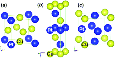
Platinum-based intermetallic nanoparticles (NPs), using the abundantly available element copper, with an average particle size of 4–5 nm on a γ-Al2O3 support were prepared successfully to reduce the consumption of Pt for the removal of CO through the catalytic oxidation reaction from flue gases. Intermetallic Pt–Cu NPs (Pt3Cu, PtCu, and PtCu3) with a Pt loading weight of 5 wt% were prepared on the γ-Al2O3 support by a simple wet impregnation method followed by calcination at various temperatures (500–800 °C) in a H2 environment and they were characterized by powder X-ray diffraction analysis (pXRD), high resolution transmission electron microscopy (HR-TEM), selective area electron diffraction (SAED) method, etc. Despite the higher synthesis temperature of these intermetallic NPs, they were not agglomerated and formed a highly ordered intermetallic structure. The surface of the intermetallic Pt–Cu NPs with cubic-type structure (Pt3Cu and PtCu3) is enclosed of {200} facets, regardless of the significant difference in their compositions. Whereas the surface of rhombohedral-type intermetallic PtCu NPs is enclosed of {104} facets. Although the Pt-loading weight of these intermetallic NPs was the same, Pt3Cu NPs showed a stable and enhanced catalytic activity compared to the other intermetallic PtCu and PtCu3 NPs. Pt3Cu NPs showed an onset and maximum conversion temperature of 50 and 125 °C, respectively. The intermetallic phase between Pt and Cu of Pt3Cu NPs did not decompose; however, the intermetallic phase did decompose for PtCu and PtCu3 NPs after catalytic CO oxidation. Unlike PtCu and PtCu3 NPs, the Pt3Cu NPs were not agglomerated and they were finely dispersed even after catalytic CO oxidation.


Introduction

Catalytic removal of carbon monoxide (CO) from flue gases is of primary importance for exhaust purification, fuel cell applications, etc.1–4 Platinum group metals (PGM) still contribute to almost all catalytic-related applications owing to their superior performance in terms of activity, stability, relative strong against poisoning moieties, etc.5 Nevertheless, there is an essential need to identify real-world catalysts as alternatives to PGM due to the huge gap between supply and demand.6 The localized minerals of PGM in the world and their continuously increasing price due to the substantial usage of PGM for a variety of catalytic and other applications7–9 are the main attributes for finding PGM alternatives. In addition, although PGM possess superior catalytic activities; however, they have certain limitations. In particular, they have poor activity at lower temperatures,10 which would force researchers further to identify alternatives to PGM for low-temperature catalytic applications. It should be noted that most of toxic gases are emitted solely under low-temperature conditions, for instance automobile exhaust emissions (i.e., cold start period).10–12 Non PGM-based catalysts, including metal oxides, mixed metal oxides, and their shape-controlled forms, have been developed as alternatives to PGM;13–19 however, they pose several limitations in terms of activity, long-term performance, stability, and poor sulfur-resistance. Therefore, considering the limitations of PGM and non-PGM-based catalysts, it would be reasonable to reduce the consumption of PGM. Therefore, considering the limitations of PGM and non-PGM-based catalysts, it would be reasonable to reduce the consumption of PGM by enhancing the catalytic activity with the same, or less, amount of PGM for targeted catalytic applications (i.e., increasing the utilization efficiency) than the conventional PGM catalysts.

The performance of the catalysts can be enhanced by heating the catalysts externally and tuning the exhaust gas composition as well as catalytic properties of the catalysts. Tuning the exhaust gas composition and the external heating of the catalysts can significantly reduce the toxic emissions; however, this is accomplished at the expenditure of higher energy.12 On the other hand, tuning the catalytic properties of the catalysts would allow us tailoring options, possibly with lower cost both in terms of composition as well as morphology. Therefore, tuning the catalytic properties of the catalysts may be one of the potential options to enhance the catalytic activity with a lower cost than that of conventional catalytic materials and/or other options to mitigate toxic emissions at a lower temperature.

Achieving of an intermetallic alloy phase between PGM and other transition metals (T) seems to be a promising strategy to reduce the consumption of PGM with superior performance owing to the changes in the atomic distance, electronic structure of component metals, d-band centers, bi-functional mechanism, etc., which would consequently influence the adsorption behavior of the gases.9,20–22 For example, CO interacts on a conventional Pt surface through a top, a bridge, and a tri-fold hollow interaction with higher adsorption energy. Eventually, a higher amount of energy is required to dissociate CO molecules from the Pt surface. However, CO interacts solely on the intermetallic phase of Pt–T through a non-competitive interaction (a top interaction) due to the different chemical nature of the adjacent atom to the Pt in the lattice of Pt–T. It has been proved that the intermetallic phase of Pt–Ti has approximately 20% less adsorption energy than that of pure Pt due to the changes in the electronic structure of Pt.23–25 In addition, the component metals of the intermetallic phase, however, in some cases, provide adsorption sites for O2, whereas Pt provides adsorption sites for CO (dual site mechanism) in the intermetallic alloys.26,27 Intermetallic alloys possess both unique surface structures and bulk properties compared to that of usual alloys or component metals that are used extensively for super-conductivity, hydrogen storage, and shape-memory related applications.28–35 It has been proved that most of the intermetallic alloy phases with d-block elements showed improved catalytic activity and ameliorated stability under harsh catalytic conditions.22,36

Recently, the intermetallic alloy phase of Pt and Cu has become the focus of interest for several catalytic applications due to the improved catalytic performance over Pt alone, abundant availability of Cu, and their lower cost.37–40 Intermetallic phases of Pt and Cu have been developed and used extensively as both cathode and anode catalysts for polymer electrolyte membrane fuel cell applications.40–42 The core–shell Pt–PtCu nanotubes were prepared using Cu nanowires through a galvanic reaction followed by etching and annealing for the oxidation reaction of formic acid and oxygen reduction in fuel cell applications.43,44 Concave PtxCuy NPs were synthesized using molten salts of KNO3 and LiNO3 and showed significant catalytic activity for the electro-oxidation of methanol and formic acid as fuels.45 Pt–Cu alloy concave nanocubes containing high-index facets were prepared by co-reduction of organometallic Pt- and Cu-precursors in the presence of capping agents and surfactants and exhibited enhanced methanol oxidation compared to commercial Pt/C for fuel cell applications. Nano-porous Cu–Pt core shell structures were achieved by the de-alloying of Cu/Al alloy followed by a galvanic replacement reaction for the methanol electro-oxidation reaction.46 A 20 g batch of core–shell catalysts containing intermetallic PtCu3 and Pt that were embedded in a carbon-support were realized as cathode materials through a galvanic reaction for a low-temperature fuel cell reaction.47 Pt–Cu bimetallic NPs were prepared by the galvanic replacement reaction facilitated by high-intensity ultrasound at low temperatures without using any surfactants and they showed an enhancement in the oxygen reduction reaction by two-fold.48 Intermetallic PtCu3 NPs were prepared with different degrees of structural ordering on a graphitic carbon support for the reduction reaction of oxygen by the sol–gel method followed by annealing at various temperatures. The partially ordered structure showed higher catalytic activity compared to the disordered structure due to the retention time of Cu in the ordered structure and an intrinsic structural effect of the alloy.49 Pt–Cu supported mesoporous graphitic carbon, as an oxygen reduction electro-catalyst, was prepared by a modified polyol process using shape-directing agents.50 De-alloyed Pt–Cu core shell NPs as cathode catalysts were prepared by voltammetric de-alloying and showed a four-fold higher oxygen reduction performance than that of state-of-the-art Pt electrocatalysts.51 The oxygen reduction reaction activity was tuned by controlled de-alloying of ordered intermetallic Cu3Pt supported on carbon, which was prepared through the impregnation method followed by heat-treatment. The authors found that electrochemical de-alloying results a thin Pt-skin on an ordered Cu3Pt core structure, but chemical leaching shows a spongy-like structure.52,53 Pt–Cu bimetallic NPs < 3 nm in size were deposited on melem-modified carbon, followed by removing 90% of the copper, showed an enhanced electro-catalytic oxygen reduction reaction.54 Bimetallic PtCu3 NPs, as oxygen reduction catalysts, were prepared using a sonochemical synthesis method. Ultrasonic waves were subjected during reduction of precursors in a non-aqueous solution to synthesize PtCu3 NPs.55 Cu–Pt alloy nanocubes, with a broad range of compositions, were prepared using stabilizing and capping agents for electro-catalytic CO2 reduction.56 The composite film of Cu–Pt NPs and poly(8-hydroxyquinoline) was prepared on a glassy carbon electrode for the hydrogen evolution reaction through a galvanic reaction.57 Al2O3 supported Pt–Cu catalysts, prepared through an impregnation technique, were used for a selective ring opening reaction of ethylcyclopentane. It was found that the changing of Cu-content modifies the catalytic mechanism of the ring opening reaction.58 Photocatalytic hydrogen production from water was achieved at a higher production rate using 1-D CuPt nanorods, as a co-catalyst, that were synthesized using hexadecylamine and hexadecanoic acid as surface ligands.59 Catalytic removal of CO from flue gases in a H2-rich environment was examined using intermetallic PtCu for fuel cell applications.5,60–65 Although alloys of Pt–Cu have been developed, most of the Pt–Cu alloys showed an alloy nature (i.e., without ordered intermetallic structure), a wide size distribution range as well as wide Pt and Cu ratio range, the existence of Cu impurities, etc., which may not be desired for achieving the targeted long-term catalytic performance.66–68 In addition, complex synthesis methods, including a galvanic replacement reaction and using capping and shape-controlling agents, were adopted to prepare Pt–Cu alloys.69–72 It should be noted that Pt forms three different ordered intermetallic phases with Cu namely: Pt3Cu, PtCu, and PtCu3 (Fig. 1). Although individual intermetallic phases of Pt–Cu have been studied, mostly for electro-catalytic applications, there has been no comparative study of these three ordered intermetallic Pt–Cu systems for thermal catalytic applications, which is of primary importance for both fundamental understanding as well as practical aspects of these promising intermetallic Pt–Cu phases. Therefore, the objective of this work is to develop a simple method to prepare the ordered intermetallic phases of Pt–Cu and access the possibility of catalytic centers for thermal catalytic applications using a model CO oxidation reaction.


image file: c6ra19602k-f1.tif
Fig. 1 Crystallographic structures of ordered intermetallic Pt3Cu (a), PtCu (b) and PtCu3 (c).

Here in, we report the facile synthesis of an intermetallic phase of Pt–Cu (Pt3Cu, PtCu, and PtCu3) in the order of 4–5 nm through a simple wet-impregnation method followed by calcination at various temperatures under a H2 environment. The formation of the intermetallic alloy phase of the synthesized Pt–Cu materials was examined by powder X-ray diffraction (pXRD) and selective area electron diffraction (SAED). The morphology of the intermetallic Pt–Cu NPs was examined using high-resolution transmission electron microscopy (HR-TEM). Inductively coupled plasma mass spectrometry (ICP-MS) was performed to quantify the amounts of Pt and Cu in the synthesized intermetallic Pt–Cu catalysts. The catalytic performance of these intermetallic phase Pt–Cu NPs was examined by the oxidation reaction of CO. The stability in terms of intermetallic phase and morphology of these intermetallic Pt–Cu NPs after catalytic reactions was examined systematically using pXRD and HR-TEM.

Experimental section

Materials and methods

The precursors, chloroplatinic acid hexahydrate (H2PtCl6·6H2O) (Pt assay: ≥37.50%) and copper(II) 2,4-pentanedionate (C10H14CuO4) (98%) were purchased from Sigma Aldrich and Alfa Aesar, respectively, for the synthesis of the intermetallic alloy phase of Pt and Cu. γ-Al2O3 beads was purchased from Sasol, Germany. Al2O3 beads were crushed using a mixture and mortar and pestle each for 30 min to obtain a fine Al2O3 powder. High performance liquid chromatography grade methanol was purchased from Merck Ltd. H2 gas (5% in N2) as reducing agent, CO (5%), O2 (99.99%), and He (99.998%) were purchased from Alchemie gases and chemicals Pvt. Ltd. The distilled water was prepared using a Millipore purifier system.

Synthesis of intermetallic Pt–Cu NPs on γ-Al2O3

The ordered intermetallic phase of Pt and Cu was synthesized using a wet-impregnation method followed by calcination at an elevated temperature in H2 environment. 5 wt% Pt-loading was maintained for all intermetallic Pt–Cu catalysts. The stoichiometric ratio of Pt and Cu precursors for the desired intermetallic PtCu phase (3[thin space (1/6-em)]:[thin space (1/6-em)]1, 1[thin space (1/6-em)]:[thin space (1/6-em)]1, or 1[thin space (1/6-em)]:[thin space (1/6-em)]3) were dissolved in 50 ml of methanol and the composite solutions were stirred for 30 min at room temperature. 1 g of Al2O3 powder was added to the solution and stirred for 6 h. Methanol was evaporated by heating of the solution at 70 °C. The Pt and Cu precursors coated Al2O3 powder was ground for 15 min and then calcined at 300, 500, and 800 °C for 8 h in a H2 environment. For the 1 g synthesis of intermetallic Pt–Cu intermetallic NPs on 1 g of γ-Al2O3 as catalysts, 0.1327 g (0.2562 mmol) of Pt-precursor and 0.0223 g (0.08519 mmol), 0.0671 g (0.2563 mmol), and 0.2010 g (0.7678 mmol) of Cu-precursor were weighed to prepare Pt3Cu, PtCu, and PtCu3 NPs, respectively, on the γ-Al2O3-support.

Characterization

The products were characterized by pXRD to identify the formation of an intermetallic alloy phase between Pt and Cu. The products were scanned in the 2θ range between 20 and 90° using a X-ray diffractometer (Rigaku: Miniflex-II-DD34863) using a source of CuKα radiation (λ = 0.15418 nm) operated at 30 kV and 15 mA at a step increment of 0.02° per 5 s. The morphology, including size and shape, of the synthesized products were obtained using a HR-TEM instrument (JEM-2100 F) at an acceleration voltage of 200 kV. The products were mixed with ethanol and sonicated until the solution become turbid and then dropped smoothly on carbon-coated Cu-grids (#200 mesh) followed by air drying at 40 °C. The SAED studies were performed to examine the crystal structure of the products in a randomly selected area. 10 mg of intermetallic Pt–Cu samples were digested using 10 ml of aqua regia to quantify the amounts of Pt and Cu of the synthesized catalysts by ICP-MS (PerkinElmer, NexION 300×). The products after the catalytic oxidation reaction of CO were further characterized by pXRD, TEM, particle size distribution, etc. to examine the influence of the catalysis reaction over the products.

Catalytic oxidation of CO

Catalytic CO oxidation reaction of the products was performed in a state-of-the-art fixed bed reactor equipped with a temperature programmed furnace, a gas chromatograph, and a thermal conductivity detector. An aliquot of 50 mg of the products was sandwiched between quartz wool in a quartz tube reactor (inner diameter = 5 mm) and subjected a feed gas containing CO gas (2%) and O2 (5%) in He at a constant flow rate of 50 ml min−1. The products were pre-conditioned in the H2 environment at 250 °C for 1 h in prior to the CO oxidation reaction. The composition of the feed and effluent gases from the reactor were examined from room temperature to 350 °C. The conversion efficiency of CO to CO2 was estimated as a function of temperature by taking the ratio of the concentration of CO and CO2. Triplicate experiments were performed, including the pre-treatment conditions, and the average values were taken to evaluate the catalytic performance of the intermetallic Pt–Cu catalysts.

Results and discussion

Fig. 2 shows the pXRD profiles of the products synthesized after calcination of the stoichiometric Pt and Cu precursors coated γ-Al2O3 in the presence of H2 gas (5% in N2) at various temperatures for 8 h. The characteristic diffraction peaks of the intermetallic Pt3Cu phase were obtained at 23.1°, 32.9°, 40.6°, 47.2°, 68.9°, and 83.1° for the reflection planes of (100), (110), (111), (200), (220), and (311), respectively, (Pm[3 with combining macron]m; a = 0.3852) (ICDD #04-017-6718) when the stoichiometric Pt- and Cu-precursors coated γ-Al2O3 was calcined at 800 °C, consistent with the simulated XRD lines shown in Fig. 2a. The satellite XRD peaks, due to the formation of an intermetallic phase, were not seen clearly in the pXRD profile owing to the overlapping of satellite peaks with the characteristic diffraction peaks of the γ-Al2O3 support (ESI, Fig. S1) and also their weak intensity in nature compared to the major diffraction peaks of Pt3Cu. The obtained diffraction peaks are, however, shifted to higher diffraction angles compared to the pure phase of Pt (Fm[3 with combining macron]m; a = 0.3924 nm) due to the presence of Cu in the lattice of Pt (ESI, Fig. S1). The lattice constant of Pt3Cu was calculated to be 0.3852 nm, which was smaller than that of pure phase Pt. The formation of an intermetallic Pt3Cu phase was also confirmed by the SAED studies (see Fig. 4d for the details). The characteristic diffraction peaks of ordered intermetallic PtCu phase (R[3 with combining macron]m; a = b = 0.270 nm; c = 1.2918 nm) (ICDD #04-015-2415) were obtained when the stoichiometric Pt and Cu precursors coated γ-Al2O3 was calcined at 500 °C for 8 h, as shown in Fig. 2b. The weak, but yet recognizable, characteristic satellite diffraction peaks at 20.5°, 39.2°, 52.6°, and 71.1° for the reflection plans of (003), (101), (015), and (018), respectively, were observed, due to the formation of an intermetallic PtCu phase, in addition to the main characteristic diffraction peaks at 41.0°, 48.0°, 69.6°, and 84.3° for the reflection plane of (012), (104), (110), and (116), respectively, consistent with the simulated XRD lines as shown in Fig. 2b. The lattice constants of PtCu were calculated to be 0.240 and 1.2997 nm for a and c, respectively. It is well known that a PtCu system with ordered structure forms solely the rhombohedral structure.73 Whereas, the PtCu system without an ordered structure forms a cubic structure (Fm[3 with combining macron]m, a = 3.7960 nm) (JCPDS #48-1549). The formation of rhombohedral or cubic type structures is strongly dependent on the synthesis conditions. The cubic structure of PtCu generally shows the characteristic diffraction peaks without characteristic satellite peaks; however, they are shifted to higher diffraction angles compared to pure Pt due to the absence of an ordered structure (i.e., alloy). Whereas, an intermetallic PtCu system shows the characteristic main diffraction peaks shifted to higher diffraction angles compared to Pt along with the characteristic satellite peaks due to the ordered structure (i.e., intermetallic). Fig. 2c shows the characteristic diffraction peaks corresponding to PtCu3 that were obtained when the stoichiometric Pt and Cu precursors coated γ-Al2O3 was calcined at 500 °C in a H2 environment. In addition to the main diffraction peaks observed at 42.4°, 49.3°, 72.3°, and 87.6° for the reflection planes of (111), (200), (220), and (311), respectively, the characteristic satellite peaks at 24.1°, 34.3°, 55.1°, 61.5°, and 77.5° for the reflection planes of (100), (110), (210), (211), and (300) were also clearly obtained due to intermetallic PtCu3 phase formation (Pm[3 with combining macron]m; a = 0.3692 nm) (ICDD #03-065-3247), again consistent with the simulated XRD lines (Fig. 2c). The lattice constant for the PtCu3 system was calculated to be 0.3695 nm, which is significantly smaller than the pure phase of Pt and other intermetallic Pt3Cu systems having a cubic structure. It is worthy to mention that the lattice constant of the ordered intermetallic Pt–Cu system with cubic structure decreased linearly with the increase of Cu-content in Pt due to the contraction of lattice Pt upon intermetallic phase formation between Pt and Cu. The pure intermetallic Pt–Cu phase of Pt3Cu, PtCu, and PtCu3 were not obtained when the stoichiometric precursors were calcined at lower or higher temperatures than the set calcination temperatures (ESI, Fig. S2–S4). Therefore, the calcination temperature is crucial for achieving the desired intermetallic phase between Pt and Cu under a H2 environment. The temperature of the intermetallic phase formation decreased with the increase of Cu content in the Pt–Cu system. It should be noted that the synthesized products are free from the possible by-products, for instance, Pt, Cu, Cu-oxides, as no other diffraction peaks were obtained. These results infer that the selected synthesis methodology can aid the preparation of pure phase intermetallic Pt–Cu systems without forming any impurities.
image file: c6ra19602k-f2.tif
Fig. 2 X-ray diffraction profiles of Pt3Cu/Al2O3 (a), PtCu/Al2O3 (b), and PtCu3/Al2O3 (c). The simulated reference solid lines for these intermetallic Pt–Cu systems are shown at the bottom of each profile.

TEM observation of the intermetallic Pt–Cu NPs on the γ-Al2O3 support was performed to examine their morphology, size, distribution, etc. The synthesized intermetallic Pt3Cu NPs were semi-spherical in shape and they were well-dispersed on the γ-Al2O3 support, as shown in Fig. 3a. The size of the intermetallic Pt3Cu NPs was in the range between 1 and 10 nm and the average particle size was centered at 4 nm (Fig. 3b). The intermetallic PtCu NPs also showed a similar trend to that of Pt3Cu NPs where the PtCu NPs had a semi-spherical shape and they showed relatively poor dispersion on the γ-Al2O3 support (Fig. 3c). The particle size of PtCu NPs was in the range between 1 and 11 nm and the average particle size was 4 nm. The intermetallic PtCu3 NPs also show the semi-spherical shape but they showed poor distribution on the γ-Al2O3 support compared to the other intermetallic Pt–Cu NPs. The particle size was in the range between 1 and 11 nm, almost as similar to the other intermetallic Pt–Cu NPs, and the average particle size was calculated to be 5 nm. It is worthy to note that the intermetallic Pt–Cu NPs on the γ-Al2O3 support were not agglomerated, although they were synthesized at a higher temperature (500 and 800 °C) in the presence of H2. Moreover, both the shape and the average particle size of Pt–Cu NPs on the γ-Al2O3 support did not change significantly, irrespective of the significant difference in composition of the intermetallic Pt–Cu NPs. These results infer that the finely dispersed intermetallic Pt–Cu NPs can be synthesized on the γ-Al2O3 support without any agglomeration at elevated temperatures in the presence of H2.


image file: c6ra19602k-f3.tif
Fig. 3 TEM images and the particle size distributions of Pt3Cu/Al2O3 (a, b), PtCu/Al2O3 (c, d), and PtCu3/Al2O3 (e, f).

HR-TEM observation of the intermetallic Pt–Cu NPs was performed to examine the atomic ordering, d-spacing, etc. Fig. 4a shows the HR-TEM image of a Pt3Cu NP on the γ-Al2O3 support, which showed the atomic fringes with the d-spacing value of 0.191 nm corresponding to the {200} facet. PtCu NPs also showed the ordered structure with atomic fringes; however, they enclosed the {104} facet, as shown in the HR-TEM image (Fig. 4b). The d-spacing value of PtCu NPs from the atomic fringes was calculated to be 0.189 nm. Fig. 4c shows the HR-TEM image of a PtCu3 NP on the γ-Al2O3 support. Clear atomic fringes were observed enclosing the {200} facet due to the ordered structures with a d-spacing value of 0.182 nm. PtCu3 NP was embedded in the γ-Al2O3 support, as also clearly seen in Fig. 4c. It should be noted that the d-spacing of these intermetallic systems decreased with the increase of Cu-content in the Pt lattice, consistent with the reported results.69 It seems that the selected synthesis conditions favor the formation of an intermetallic phase with the ordered structure, which was not altered even by the increase of Cu-content in the Pt lattice. Moreover, the ordered cubic-type structure of the Pt–Cu system (Pt3Cu and PtCu3) favors the formation of the {200} facet on their surface under the selected synthesis conditions.


image file: c6ra19602k-f4.tif
Fig. 4 HR-TEM images and SAED pattern of Pt3Cu/Al2O3 (a, d), PtCu/Al2O3 (b, e), and PtCu3/Al2O3 (c, f).

SAED studies were performed further on the intermetallic Pt–Cu NPs dispersed on the γ-Al2O3 support to ensure the formation of the intermetallic phase between Pt and Cu. Fig. 4d shows the SAED pattern of Pt3Cu NPs that shows a set of strong concentric rings corresponding to the reflection planes of {111}, {200}, and {311}, that are consistent with the pXRD results. In addition to these strong concentric rings, a couple of weak concentric rings, corresponding to the reflection planes of {100} and {110}, were also observed. Although the characteristic satellite peaks for the Pt3Cu intermetallic phase were not seen clearly in the pXRD profile (Fig. 2a), the characteristic reflection planes for the intermetallic Pt3Cu phase were observed in the SAED pattern. Similarly, the weak concentric rings, corresponding to the reflection planes of {003} and {101}, were observed, due to the intermetallic phase of PtCu, in addition to the main reflection planes of {012}, {104}, {110}, and {116}, as can be seen clearly as strong concentric rings (Fig. 4e), consistent with the pXRD results (Fig. 2b). The SAED pattern of PtCu3 NPs also clearly shows both the strong concentric rings for the reflection planes of {111}, {200}, and {311} and the weak concentric rings for the reflection planes of {100} and {110} (Fig. 4f), similar to Pt3Cu NPs and consistent again with the pXRD results (Fig. 2c). Overall, the SAED patterns of the Pt–Cu NPs dispersed on the γ-Al2O3 support also ensure the formation of an intermetallic phase between Pt and Cu. These results infer that intermetallic Pt–Cu NPs with an average size of 4–5 nm can be synthesized on the γ-Al2O3 support without forming any impurities through the selected synthesis method. By considering the widely accepted factors, for instance alloying of Pt with the d-block elements, achieving a particle size smaller than 5 nm with an ordered structure would improve the catalytic performance of Pt. The present simple synthesis methodology enables one to prepare the potential intermetallic systems with an ordered structure at a smaller size on the targeted support for variety of catalytic applications. Oezaslan et al. also prepared the intermetallic Pt–Cu systems on a high surface area carbon support as electrode catalysts for the oxygen reduction reaction for fuel cell applications.74

ICP-MS experiments were performed to quantify the amounts of Pt and Cu in the synthesized intermetallic Pt–Cu catalysts (ESI, Table 1). The estimated amounts of Pt for all the intermetallic Pt–Cu catalysts were in the range between 0.48 to 0.52 mg, closer to that of the calculated Pt amounts (0.5 mg), which was almost equal to 5 wt% with respect to the γ-Al2O3-support (1 g). Similarly, the amount of Cu was estimated to be 0.062, 0.156, and 0.53 mg, which is equal to 0.62, 1.56, and 5.3 wt% of Cu in the case of intermetallic Pt3Cu, PtCu, and PtCu3 catalysts, respectively. These results infer that the present synthesis method enables one to prepare the intermetallic Pt–Cu catalysts with the desired loading weight of Pt without any significant difference in the Pt amounts, even after synthesis.

CO oxidation, as a model reaction of these intermetallic Pt–Cu NPs on the γ-Al2O3 support, was performed carefully to examine their catalytic performance. All other conditions for the CO oxidation reaction, including pre-treatment, were maintained same throughout the catalytic evaluations. All these intermetallic catalysts showed catalytic activity in the tested temperature region; however, the onset and maximum CO conversion temperature were significantly different from each other. Pt3Cu/Al2O3 showed the better catalytic CO oxidation performance compared to the other PtCu/Al2O3 and PtCu3/Al2O3. Despite no significant difference in the particle size (4–5 nm) of these intermetallic Pt–Cu NPs on the γ-Al2O3 support, they showed a considerable difference in the catalytic CO oxidation performance (Fig. 5a). As can be seen in more detail in Fig. 5b, the onset temperature (CO conversion ≦5%) of Pt3Cu/Al2O3 was 50 °C, which was significantly lower than that of PtCu/Al2O3 and PtCu3/Al2O3, which showed the onset temperature at 125 and 175 °C, respectively. The maximum CO conversion temperature also shows a similar trend where Pt3Cu/Al2O3 showed the maximum CO conversion temperature at 125 °C, which was again significantly lower than the other intermetallic Pt–Cu catalysts. PtCu/Al2O3 and PtCu3/Al2O3 showed the maximum CO conversion temperatures at 225 and 275 °C, respectively. Although the Pt loading weight (5 wt%) of these intermetallic catalysts was the same, they showed a significant difference in the catalytic CO oxidation performance likely due to the difference in the electronic structure. Attempts will be made to study the electronic structure of these intermetallic Pt–Cu NPs to rationalize the observed difference in the catalytic performance.


image file: c6ra19602k-f5.tif
Fig. 5 Comparison of catalytic CO oxidation performance (a) and onset (open bar) and maximum conversion temperature (closed bar) (b) of Pt3Cu/Al2O3, PtCu/Al2O3, and Pt3Cu/Al2O3.

pXRD analysis of the intermetallic Pt–Cu NPs on the γ-Al2O3 support after catalytic CO oxidation was performed to examine the stability of these catalysts. Fig. 6a shows the pXRD profile of Pt3Cu/Al2O3 after catalytic CO oxidation, which shows the characteristic diffraction peaks of Pt3Cu consistent with the pXRD profile of fresh Pt3Cu/Al2O3 (Fig. 2a). PtCu/Al2O3 also shows no significant difference with the fresh PtCu/Al2O3, where the main characteristic diffraction peaks of PtCu were observed even after catalytic CO oxidation. It should be noted, however, that the characteristic satellite peaks due to the intermetallic phase of PtCu were not observed after CO oxidation (Fig. 6b), where they can be seen clearly in the pXRD profile of fresh PtCu/Al2O3 (Fig. 2b). Unlike Pt3Cu/Al2O3 and PtCu/Al2O3, PtCu3/Al2O3 showed significant changes both in terms of peak intensity as well as peak position in the pXRD profile after CO oxidation (Fig. 6c) compared to the fresh PtCu3/Al2O3, where the characteristic main diffraction peaks were shifted to the lower diffraction angles, which are closer to pure phase Pt. The characteristic satellite peaks of PtCu3/Al2O3 completely disappeared after the catalytic CO oxidation reaction due to the decomposition of the intermetallic phase of PtCu3. In addition, the peak intensity of PtCu3 decreased drastically after the catalytic CO oxidation reaction compared to fresh PtCu3/Al2O3.


image file: c6ra19602k-f6.tif
Fig. 6 X-ray diffraction profiles of Pt3Cu/Al2O3 (a), PtCu/Al2O3 (b), and Pt3Cu/Al2O3 (c) after catalytic CO oxidation.

TEM analysis was further performed to examine the influence of catalytic conditions on the morphology, size of the particles and their dispersion, etc. of the intermetallic Pt–Cu on the γ-Al2O3 support after the CO oxidation reaction. Fig. 7 shows the TEM image of Pt3Cu/Al2O3, PtCu/Al2O3, and PtCu3/Al2O3 and their particle size distribution after the CO oxidation reaction. No significant changes in terms of morphology as well as particle size distribution were observed in the case of Pt3Cu/Al2O3 after catalytic CO oxidation. The Pt3Cu NPs are well dispersed and had a semi-spherical shape that was virtually same as fresh Pt3Cu/Al2O3 (Fig. 3a), as shown in Fig. 7a. The size of the Pt3Cu NPs on the γ-Al2O3 support was also not changed at all and ranged between 1 and 10 nm with an average Pt3Cu NPs size centered at 4 nm. There was virtually no difference in terms of the morphology observed in the case of PtCu/Al2O3, where the PtCu NPs also showed a semi-spherical shape, similar to fresh PtCu/Al2O3 (Fig. 7c). However, the PtCu NPs were relatively agglomerated compared to the fresh PtCu NPs (Fig. 3c) after catalytic CO oxidation. The particle size was in the range between 1 and 15 nm and the average particle size was centered at 6 nm, as shown in Fig. 7d. Notably, the PtCu3 NPs were largely agglomerated on the γ-Al2O3 support and the semi-spherical shaped particles of the fresh PtCu3 (Fig. 3e) were changed in to various shapes after the catalytic CO oxidation (Fig. 7e). The size of the particles was widely distributed, which was in the range between 7 and 32 nm. These results unambiguously suggest that Pt3Cu NPs are stable in terms of their intermetallic phase, size, morphology, dispersion, etc. on the γ-Al2O3 support compared to the other intermetallic PtCu and PtCu3 NPs after catalytic CO oxidation.


image file: c6ra19602k-f7.tif
Fig. 7 TEM images and the particle size distribution of Pt3Cu/Al2O3 (a, b), PtCu/Al2O3 (c, d), and Pt3Cu/Al2O3 (e, f) after catalytic CO oxidation.

Conclusions

Intermetallic Pt–Cu (Pt3Cu, PtCu, and PtCu3) NPs were successfully prepared on the γ-Al2O3-support without any impurities through the wet-impregnation method via coating of the stoichiometric Pt and Cu precursors onto the γ-Al2O3 support followed by treating them at elevated temperature under a H2 environment. The semi-spherical intermetallic Pt–Cu NPs, with an average size of 4–5 nm, are well dispersed on the γ-Al2O3 support regardless of the significant difference in their composition. Despite the higher synthesis temperature, the cubic structure of Pt3Cu and PtCu3 NPs are not agglomerated and forms highly ordered intermetallic structures. The surface of these intermetallic NPs are enclosed by the {200} facet, whereas the rhombohedral structure of PtCu has the {104} facet on its surface. Pt3Cu/Al2O3 catalysts showed the best catalytic performance for the oxidation reaction of CO in terms of onset as well as maximum conversion temperature among the other intermetallic PtCu/Al2O3 and PtCu3/Al2O3 catalysts. Pt3Cu NPs are stable in terms of the crystal structure, morphology, etc. compared to the other PtCu and PtCu3 NPs after the catalytic CO oxidation reaction. The dispersion of Pt3Cu NPs on the γ-Al2O3 support was virtually unchanged after the catalytic CO oxidation reaction; but, it did change for PtCu and PtCu3 NPs. The reported synthesis method (i.e., achieving of the ordered intermetallic Pt–Cu systems with smaller size) can be extended to the other order intermetallic systems that can find the other catalytic- and optical-related applications.

Acknowledgements

Dr G. Saravanan gratefully acknowledge Science and Engineering Research Board (SERB), Department of Science & Technology (DST), India for the financial support under young scientist scheme (SB/FT/CS-151/2013). KRC No. KRC\2016\MAY\EMD\6.

Notes and references

  1. H. C. Yao and Y. F. Y. Yao, J. Catal., 1984, 86, 254–265 CrossRef CAS.
  2. C. Lamy, E. M. Belgsir and J.-M. Léger, J. Appl. Electrochem., 2001, 31, 799–809 CrossRef CAS.
  3. B. Du and Y.-Y. Tong, J. Phys. Chem. B, 2005, 109, 17775–17780 CrossRef CAS PubMed.
  4. Y.-Y. Tong, H. S. Kim, P. K. Babu, P. Waszczuk, A. Wieckowski and E. Oldfield, J. Am. Chem. Soc., 2002, 124, 468–473 CrossRef CAS PubMed.
  5. S. H. Oh and R. M. Sinkevitch, J. Catal., 1993, 142, 254–262 CrossRef CAS.
  6. J. Matthey, PGM Market Report, May 2015, pp. 1–38 Search PubMed.
  7. A. Chen and P. Holt-Hindle, Chem. Rev., 2010, 110, 3767–3804 CrossRef CAS PubMed.
  8. H. A. Gasteiger and N. M. Markovic, Science, 2009, 324, 48–49 CrossRef CAS PubMed.
  9. V. R. Stamenkovic, B. Fowler, B. S. Mun, G. Wang, P. N. Ross, C. A. Lucas and N. M. Markovic, Science, 2007, 315, 493–497 CrossRef CAS PubMed.
  10. R. J. Farrauto and R. M. Heck, Catal. Today, 1999, 51, 351–360 CrossRef CAS.
  11. R. S. D. Bosteels, Platinum Met. Rev., 2002, 46, 37 Search PubMed.
  12. M. Skoglundh and E. Fridell, Top. Catal., 2004, 28, 79–87 CrossRef CAS.
  13. P. Thormählen, E. Fridell, N. Cruise, M. Skoglundh and A. Palmqvist, Appl. Catal., B, 2001, 31, 1–12 CrossRef.
  14. Y.-F. Y. Yao, J. Catal., 1975, 36, 266–275 CrossRef CAS.
  15. G. Neri, G. Rizzo, S. Galvagno, A. Donato, M. G. musolino and R. Pietropaolo, Appl. Catal., B, 2001, 42, 381–391 CrossRef.
  16. Y. Teraoka, K. Kanada and S. Kagawa, Appl. Catal., B, 2001, 34, 73–78 CrossRef CAS.
  17. Y. Wei, Z. Zhao, X. Yu, B. Jin, J. Liu, C. Xu, A. Duan, G. Jiang and S. Ma, Catal. Sci. Technol., 2013, 3, 2958–2970 CAS.
  18. E. S. J. Lox, B. H. Engler, F. J. Janssen, R. L. Garten, R. A. Dalla Betta, J. C. Schlatter, Z. Ainbinder, L. E. Manzer, M. J. Nappa, V. N. Parmon and K. I. Zamaraev, in Environmental Catalysis: Handbook of Heterogeneous Catalysis, ed. G. Ertl, H. Knözinger and J. Weitkamp, Wiley-VCH, Weinheim, 1997, p. 1581 Search PubMed.
  19. A.-A. A. Said, M. M. M. Abd El-Wahab, S. A. Soliman and M. N. Goda, Process Saf. Environ. Prot., 2016, 102, 370–384 CrossRef CAS.
  20. V. R. Stamenkovic, B. S. Mun, M. Arenz, K. J. J. Mayrhofer, C. A. Lucas, G. Wang, P. N. Ross and N. M. Markovic, Nat. Mater., 2007, 6, 241–247 CrossRef CAS PubMed.
  21. J. Greeley, I. E. L. Stephens, A. S. Bondarenko, T. P. Johansson, H. A. Hansen, T. F. Jaramillo, J. Rossmeisl, I. Chorkendorff and J. K. Norskov, Nat. Chem., 2009, 1, 552–556 CrossRef CAS PubMed.
  22. H. Abe, H. Yoshikawa, N. Umezawa, Y. Xu, G. Saravanan, G. V Ramesh, T. Tanabe, R. Kodiyath, S. Ueda, N. Sekido, Y. Yamabe-Mitarai, M. Shimoda, T. Ohno, F. Matsumoto and T. Komatsu, Phys. Chem. Chem. Phys., 2015, 17, 4879–4887 RSC.
  23. U. Bardi, D. Dahlgren and P. N. Ross, J. Catal., 1986, 100, 196–209 CrossRef CAS.
  24. G. Saravanan, H. Abe, Y. Xu, N. Sekido, H. Hirata, S. Matsumoto, H. Yoshikawa and Y. Yamabe-Mitarai, Langmuir, 2010, 26, 11446–11451 CrossRef CAS PubMed.
  25. H. Abe, F. Matsumoto, L. R. Alden, S. C. Warren, H. D. Abruña and F. J. DiSalvo, J. Am. Chem. Soc., 2008, 130, 5452–5458 CrossRef CAS PubMed.
  26. E. Antolini, J. R. C. Salgado and E. R. Gonzalez, Appl. Catal., B, 2006, 63, 137–149 CrossRef CAS.
  27. X. Zhao, M. Yin, L. Ma, L. Liang, C. Liu, J. Liao, T. Lu and W. Xing, Energy Environ. Sci., 2011, 4, 2736–2753 CAS.
  28. D. Weller, A. Moser, L. Folks, M. E. Best, W. Lee, M. F. Toney, M. Schwickert, J. U. Thiele and M. F. Doerner, IEEE Trans. Magn., 2000, 36, 10–15 CrossRef CAS.
  29. S. Sun, C. B. Murray, D. Weller, L. Folks and A. Moser, Science, 2000, 287, 1989–1992 CrossRef CAS PubMed.
  30. C.-M. Kuo, P. C. Kuo and H.-C. Wu, J. Appl. Phys., 1999, 85, 2264 CrossRef CAS.
  31. M. Watanabe, T. Nakayama, K. Watanabe, T. Hirayama and A. Tonomura, Mater. Trans., JIM, 1996, 37, 489–493 CrossRef CAS.
  32. D. Weller and M. F. Doerner, Annu. Rev. Mater. Sci., 2000, 30, 611–644 CrossRef CAS.
  33. S. D. Bader, Rev. Mod. Phys., 2006, 78, 1–15 CrossRef CAS.
  34. T. Komatsu and A. Tamura, J. Catal., 2008, 258, 306–314 CrossRef CAS.
  35. W. E. Wallace, Chem. Tech., 1982, 12, 752–754 CAS.
  36. D. Xiang and L. Yin, J. Mater. Chem., 2012, 22, 9584–9593 RSC.
  37. M. Bele, P. Jovanovic, A. Pavlisic, B. Jozinovic, M. Zorko, A. Recnik, E. Chernyshova, S. Hocevar, N. Hodnik and M. Gaberscek, Chem. Commun., 2014, 50, 13124–13126 RSC.
  38. H. Zhao, C. Yu, H. You, S. Yang, Y. Guo, B. Ding and X. Song, J. Mater. Chem., 2012, 22, 4780–4789 RSC.
  39. N. Hodnik, C. Jeyabharathi, J. C. Meier, A. Kostka, K. L. Phani, A. Recnik, M. Bele, S. Hocevar, M. Gaberscek and K. J. J. Mayrhofer, Phys. Chem. Chem. Phys., 2014, 16, 13610–13615 RSC.
  40. L. Su, S. Shrestha, Z. Zhang, W. Mustain and Y. Lei, J. Mater. Chem. A, 2013, 1, 12293–12301 CAS.
  41. C.-M. Zhu, A. Gao, Y. Wang and Y. Liu, Chem. Commun., 2014, 50, 13889–13892 RSC.
  42. H. Zhao, C. Yu, H. You, S. Yang, Y. Guo, B. Ding and X. Song, J. Mater. Chem., 2012, 22, 4780–4789 RSC.
  43. C. Du, M. Chen, W. Wang, Q. Tan, K. Xiong and G. Yin, J. Power Sources, 2013, 204, 630–635 CrossRef.
  44. L. Su, S. Shrestha, Z. Zhang, W. Mustaina and Y. Lei, J. Mater. Chem. A, 2013, 1, 12293–12301 CAS.
  45. H. Zhao, C. Yu, H. You, S. Yang, Y. Guo, B. Dinga and X. Song, J. Mater. Chem., 2012, 22, 4780–4789 RSC.
  46. C. Xu, Y. Liu, J. Wang, H. Geng and H. Qiu, ACS Appl. Mater. Interfaces, 2011, 3, 4626–4632 CAS.
  47. M. Bele, P. Jovanovic, A. Pavlisic, B. Jozinovic, M. Zorko, A. Recnik, E. Chernyshova, S. Hocevar, N. Hodnik and M. Gaberscek, Chem. Commun., 2014, 50, 13124–13126 RSC.
  48. Z. Sun, J. Masa, W. Xia, D. Konig, A. Ludwig, Z. Li, M. Farle, W. Schuhmann and M. Muhler, ACS Catal., 2012, 2, 1647–1653 CrossRef CAS.
  49. N. Hodnik, C. Jeyabharathi, J. Meier, A. Kostka, K. Phani, A. Recnik, M. Bele, S. Hocevar, M. Gaberscek and K. Mayrhofer, Phys. Chem. Chem. Phys., 2014, 16, 13610–13615 RSC.
  50. G. Gupta, D. Slanac, P. Kumar, J. Wiggins-Camacho, X. Wang, S. Swinnea, K. More, S. Dai, K. Stevenson and K. Johnston, Chem. Mater., 2009, 21, 4515–4526 CrossRef CAS.
  51. P. Mani, R. Srivastava and P. Strass, J. Phys. Chem. C, 2008, 112, 2770–2778 CAS.
  52. D. Wang, Y. Yu, H. Xin, R. Hovden, P. Ercius, J. Mundy, H. Chen, J. Richard, D. Muller, F. DiSalvo and H. Abrun, Nano Lett., 2012, 12, 5230–5238 CrossRef CAS PubMed.
  53. D. Wang, Y. Yu, J. Zhu, S. Liu, D. Muller and H. Abrun, Nano Lett., 2015, 15, 1343–1348 CrossRef CAS PubMed.
  54. C. Zhu, A. Gao, Y. Wang and Y. Liu, Chem. Commun., 2014, 50, 13889–13892 RSC.
  55. C. Gumeci, D. Cearnaigh, D. Casadonte and C. Korzeniewski, J. Mater. Chem. A, 2013, 1, 2322–2330 Search PubMed.
  56. X. Zhao, B. Luo, R. Long, C. Wang and Y. Xiong, J. Mater. Chem. A, 2015, 3, 4134–4138 CAS.
  57. J. Raoof, R. Ojani, S. Esfeden and S. Nadimi, Int. J. Hydrogen Energy, 2010, 35, 3937–3944 CrossRef CAS.
  58. M. Boutahala, B. Djellouli, N. Zouaoui and F. Garin, Catal. Today, 2004, 89, 379–385 CrossRef CAS.
  59. F. Yu, X. Xu, C. Baddeley, R. Bellabarba, P. Lignier, R. Tooze, F. Fina, J. Irvine and W. Zhou, CrystEngComm, 2014, 16, 714 Search PubMed.
  60. A. K. Santra and D. W. Goodman, Electrochim. Acta, 2002, 47, 3595–3609 CrossRef CAS.
  61. C. Song, Catal. Today, 2002, 77, 17–49 CrossRef CAS.
  62. T. Komatsu, M. Takasaki, K. Ozawa, S. Furukawa and A. Muramatsu, J. Phys. Chem. C, 2013, 117, 10483–10491 CAS.
  63. S.-I. Ito, T. Fujimori, K. Nagashima, K. Yuzaki and K. Kunimori, Catal. Today, 2000, 57, 247–254 CrossRef CAS.
  64. J. Levec, in Opportunities in Catalytic Reaction Engineering. Examples of Heterogeneous Catalysis in Water Remediation and Preferential CO Oxidation, in Chemical Engineering: Trends and Developments, ed. M. A. Galán and E. M. Del Valle, John Wiley & Sons, Ltd, Chichester, UK, 2005, pp. 103–123 Search PubMed.
  65. A. Manasilp and E. Gulari, Appl. Catal., B, 2002, 37, 17–25 CrossRef CAS.
  66. I. Dutta, M. K. Carpenter, M. P. Balogh, J. M. Ziegelbauer, T. E. Moylan, M. H. Atwan and N. P. Irish, J. Phys. Chem. C, 2010, 114, 16309–16320 CAS.
  67. G. Gupta, D. A. Slanac, P. Kumar, J. D. Wiggins-Camacho, X. Wang, S. Swinnea, K. L. More, S. Dai, K. J. Stevenson and K. P. Johnston, Chem. Mater., 2009, 21, 4515–4526 CrossRef CAS.
  68. P. Strasser, S. Koh, T. Anniyev, J. Greeley, K. More, C. Yu, Z. Liu, S. Kaya, D. Nordlund, H. Ogasawara, M. F. Toney and A. Nilsson, Nat. Chem., 2010, 2, 454–460 CrossRef CAS PubMed.
  69. C. Gumeci, D. U. Cearnaigh, D. J. Casadonte and C. Korzeniewski, J. Mater. Chem. A, 2013, 1, 2322–2330 Search PubMed.
  70. Y. Qi, T. Bian, S.-I. Choi, Y. Jiang, C. Jin, M. Fu, H. Zhang and D. Yang, Chem. Commun., 2014, 50, 560–562 RSC.
  71. F. Yu, X. Xu, C. J. Baddeley, R. M. Bellabarba, P. Lignier, R. P. Tooze, F. Fina, J. S. T. Irvine and W. Zhou, CrystEngComm, 2014, 16, 1714–1723 RSC.
  72. H. M. Abdel Dayem, Platinum Met. Rev., 2007, 51, 138–144 CrossRef CAS.
  73. K. Mitsui, M. Takahashi and T. Takezawa, Philos. Mag. Lett., 1998, 77, 49–57 CrossRef CAS.
  74. M. Oezaslan, F. Hasche and P. Srasser, J. Electrochem. Soc., 2012, 159, B444–B454 CrossRef CAS.

Footnote

Electronic supplementary information (ESI) available: pXRD profiles of γ-Al2O3 Pt/γ-Al2O3 and Pt- and Cu-precursors on γ-Al2O3 at various set temperatures, ICP-MS results. See DOI: 10.1039/c6ra19602k

This journal is © The Royal Society of Chemistry 2016
Click here to see how this site uses Cookies. View our privacy policy here.