DOI:
10.1039/C6RA19188F
(Paper)
RSC Adv., 2016,
6, 98337-98343
Manganese oxide films with controlled oxidation state for water splitting devices through a combination of atomic layer deposition and post-deposition annealing†
Received
28th July 2016
, Accepted 9th October 2016
First published on 10th October 2016
Abstract
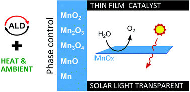
Solar hydrogen devices combine the power of photovoltaics and water electrolysis to produce hydrogen in a hybrid form of energy production. To engineer these into integrated devices (i.e. a water splitting catalyst on top of a PV element), the need exists for thin film catalysts that are both transparent for solar light and efficient in water splitting. Manganese oxides have already been shown to exhibit good water splitting performance, which can be further enhanced by conformal coating on high surface-area structures. The latter can be achieved by atomic layer deposition (ALD). However, to optimize the catalytic and transparency properties of the water splitting layer, an excellent control over the oxidation state of the manganese in the film is required. So far MnO, Mn3O4 and MnO2 ALD have been shown, while Mn2O3 is the most promising catalyst. Therefore, we investigated the post-deposition oxidation and reduction of MnO and MnO2 ALD films, and derived strategies to achieve every phase in the MnO–MnO2 range by tuning the ALD process and post-ALD annealing conditions. Thin film Mn2O3 is obtained by thermal reduction of ALD MnO2, without the need for oxidative high temperature treatments. The obtained Mn2O3 is examined for solar water splitting devices, and compared to the as-deposited MnO2. Both thin films show oxygen evolution activity and good solar light transmission.
1 Introduction
The rise of the internet of things (IoT) requires, besides sensors and energy storage, small and autonomous energy production. Integrated solar hydrogen devices consist of a photo-active material buried beneath a water splitting catalyst. The catalyst on top has to fulfil three requirements: (1) good water splitting performance, (2) excellent solar light transmission and (3) good stability. In order to minimize the local current density and improve criterion (1) and (3), thin films on high surface area 3D structures can be utilized. Atomic layer deposition (ALD) allows for conformal deposition of thin films of many metal oxides on very high aspect ratio structures,1 meeting the third requirement. Concerning the first two requirements, benchmark catalysts such as platinum suffer from high cost, low abundance and no solar light transmission. Other benchmark catalysts such as IrOx may be more transparent, but iridium has an even lower abundance than platinum. Transparent, abundant and low cost oxides, such as manganese oxide, are more favourable in this respect. Thin film manganese oxides have been investigated as water oxidation catalysts in many reported studies.2–7 In our previous work, we showed that the oxidation state of Mn can be controlled during ALD growth with the Mn(thd)3 precursor by selecting the proper oxidative or reductive reactant gas or -plasma during the ALD process. Mn(+II)O, Mn3(+II/+III)O4 and Mn(+IV)O2 are achievable by using ammonia plasma, water plasma and ozone, respectively.8 Mn(EtCp)2 was reported to grow the bivalent manganese oxide Mn(+II)O.4,9 Although Mn2O3 is reported as the most active catalyst for the oxygen evolution reaction (OER) thanks to the high activity of the Mn(+III) sites,5,10 direct ALD of Mn2(+III)O3 thin films has not been reported so far.1,8,11,12 Pickrahn et al. evaluated an ALD-based Mn2O3 catalyst for OER by depositing MnO ALD and oxidizing it to Mn2O3.4 In that case, it was found that the oxidized Mn2O3 outperformed the as-deposited MnO. Li et al. evaluated the influence of post-annealing of ALD-grown β-MnO2 in oxidizing ambients up to 700 °C.13 However, the oxidizing ambient used in those studies to increase the manganese oxidation state could have a detrimental effect on the surrounding and underlying materials in integrated devices. From the manganese phase diagram and earlier studies on bulk manganese oxides it is shown that re-oxidation of bulk manganese oxides up to Mn2O3 is possible, and reduction down to MnO and even manganese metal can be obtained by raising temperature and varying the oxygen partial pressures.4,14–16 Faster reduction can be achieved when introducing a hydrogen atmosphere to manganese oxides.16,17
In this work, we explore various annealing routes to control the oxidation state of ALD-grown manganese oxide thin films by tuning the ALD processing conditions and post-ALD anneal conditions. Starting from the two extrema in the manganese oxide spectrum, MnO and MnO2, we used XPS and in situ XRD to monitor the phase evolution in oxidizing, inert and reducing atmospheres from room temperature up to 900 °C. Since roughness is also a determining factor for catalytic performance, the surface topography of the oxidized and reduced thin films is systematically evaluated by atomic force microscopy. This paper reports a systematic study of possible pathways towards the full range of manganese oxides that can be obtained by tuning ALD process parameters and the post-ALD annealing conditions, such as temperature (20 °C to 900 °C) and ambient (oxidating, inert and reducing) as parameters. Our results show that thin film Mn2O3 can be obtained by heating ALD MnO2 in an inert atmosphere. This enables a wider range of sensitive substrates. The MnO2 and MnO2-derived Mn2O3 were evaluated as water oxidation catalysts, and both perform well when compared to a known catalyst such as platinum, with the added advantage of excellent solar light transmission coefficients and high abundance.
2 Experimental
The manganese oxides were grown in an experimental high-vacuum ALD setup with a base pressure of 10−7 mbar.8,18–20 The ALD processes are based on the Mn(thd)3 precursor (Tris(2,2,6,6-tetramethyl-3,5-heptanedionato)manganese from Strem, 99%). In this work we examine the oxidation and reduction behaviour of MnO2 and MnO thin films grown by thermal ALD (Mn(thd)3 and O3 ALD) and PE-ALD (Mn(thd)3 and NH3 plasma ALD) at 180 °C, respectively. ALD characteristics and growth conditions can be found in our earlier report.8 MnO and MnO2 films obtained from 1000 cycles of atomic layer deposition were grown on H-terminated Si (by stripping the native oxide by etching in a 5% HF solution for 1 min before deposition), 100 nm thermally grown SiO2 on a Si substrate, resulting in a 37 nm and 20 nm film, respectively.
In situ XRD was used to determine the crystal state during annealing, measuring with the X-ray source (Cu Kα radiation at 0.154 nm) and linear detector in fixed positions at 20° and 35° respectively, resulting in a 24° to 44° window in 2θ with a 5° offset to avoid substrate peaks. Annealing was done in a stainless steel chamber, under a flow of 20 l h−1 of oxygen (Praxair, 99.999%), helium (Praxair, 99.999%) or forming gas (helium + 5% H2, Praxair, 99.999%), at a heating rate of 0.25 °C s−1 from room temperature to 900 °C.21,22 To verify the oxidation states derived from the crystal state found in XRD (and to confirm the absence of an amorphous fraction with a potentially different oxidation state) selected samples were investigated by XPS, which was performed using Al Kα radiation (0.834 nm) under a take-off angle of 45° in a high-vacuum chamber (2 × 10⁻⁹ mbar). A resolution of 0.108 eV was obtained. The Mn–O–Mn bond was investigated by evaluation of the binding energy difference between the Mn 2p3/2 and the O 1s signals (Mn-bond component).8,13,14,23–25
The film morphology was probed on the as-deposited and quenched samples using a Bruker Dimension Edge atomic force microscope (AFM) and film rms roughness was determined from 1 μm × 1 μm AFM images. Film surface morphology was further examined using a high-vacuum electron microscope (FEI Quanta 200F).
MnO2 and Mn2O3 are examined for their catalytic properties. To this end, 200 ALD cycles of MnO2 (resulting in a 3 nm film) were deposited on Toray carbon paper as an electrical contact for the activity measurements, and MnO2 films were deposited on glass substrates for the investigation of their optical properties. MnO2 films were evaluated as such, and converted to Mn2O3 by post-deposition annealing. Transmission UV-Vis spectroscopy of MnO2 and Mn2O3 on glass substrates was carried out using an Infinite M200 Pro instrument (Tecan). Light absorbance A(λ) of the glass substrate and of the films deposited on the glass substrate was measured, and the former was subtracted from the latter to correct for the substrate. The absorbance, including components from both light absorption and reflection, was converted to a transmittance using T(λ) = 10−A(λ). Linear voltammetric sweeps in the anodic direction were performed on the as-prepared samples with a sweep rate of 2 mV s−1 (Experimental details described in ESI†).
3 Results and discussion
3.1 In situ XRD and AFM results
In situ XRD patterns measured on both films during annealing in oxidizing, inert and reducing ambient are shown in Fig. 1. The XRD peaks clearly reveal the oxidation and reduction behaviour of the manganese oxides thin films under study. A quench of every intermediate phase was taken to be examined separately. The oxidation state of the manganese in selected samples was examined by XPS (ESI†) which matched the crystalline phase, indicating that no amorphous fraction was present with a different manganese oxidation state. The quenched samples all remained in the crystalline phase they were in at the time of the anneal, demonstrating that all these intermediate phase formations observed in in situ XRD are stable when quenched (Fig. 2).
 |
| Fig. 1 In situ XRD measurements from room temperature to 900 °C at a heating rate of 0.25 °C s−1 in oxygen, helium and hydrogen ambient of the as-deposited MnO and MnO2 films: MnO2 in O2 ambient (a), He ambient (b) and H2/He ambient (c), and MnO in O2 ambient (d), He ambient (e) and H2/He ambient (f). Peak identification was performed using the JCPDS database: β-MnO2 (81-2261), Mn2O3 (89-2809), Mn3O4 (24-0734), MnO (75-0625), α-Mn (32-0637), Mn2SiO4 (35-0747) and MnSiO3 (89-2809). | |
 |
| Fig. 2 XRD spectra of selected quenches, starting from the ALD MnO2 film (top) and from the ALD MnO film (bottom). From left to right: oxygen, helium and forming gas ambient, respectively. A background was subtracted from the measured spectra, and they are offset to allow better visualisation. Peak identification was performed using the JCPDS database (see Fig. 1), with reported peak positions shown on the graphs. | |
Next, we examined the roughness of the as deposited films and the selected quenches. Fig. 3 shows AFM images of the as deposited samples, as well as the selected quenches. The as-deposited films are shown to be very smooth, with a roughness of only 0.40 nm and 0.86 nm for the MnO and MnO2 films, respectively. Some quenches show little evolution, but most of the high-temperature quenches show severely changed morphology or increased roughness.
 |
| Fig. 3 1 by 1 μm AFM images of the as deposited MnO2 (a) and MnO (b) ALD films on the SiO2 substrate. An AFM image of the H2O PE-ALD film (c), resulting in a Mn3O4 film is added for completeness (process conditions according to earlier work8). AFM images of quenches are shown: MnO2 annealed in oxygen to 900 °C (d), in helium to 500 °C (e), 750 °C (f) and 900 °C (g), and in He/H2 to 500 °C (h), and MnO annealed in oxygen to 425 °C (i) and 900 °C (j) and helium to 900 °C (k). Images are set to the same 15 nm colour scale to allow direct comparison. | |
3.2 Discussion of the phase evolution
A summary of the phase formation and roughness evolution is presented in Fig. 4. This figure gives a systematic overview of different strategies that enable achieving a particular phase and resulting roughness. At low temperature and high oxygen ambient, the MnO2 phase is the stable phase.26 However, it is kinetically not possible to oxidize the MnO films to MnO2 under standard atmospheric pressure conditions before entering the temperature regime where Mn2O3 becomes more stable, leaving only the as-deposited films grown using the ozone-based process with the Mn in the +IV oxidation state. Indeed, in an oxidizing ambient, the MnO films quickly transverse the Mn3O4 phase to end up in the Mn2O3 phase, as can be seen in Fig. 1(d). Even though these films undergo two phase transitions, this is still a smoother film than the Mn2O3 obtained from the MnO2 films in oxidizing or inert ambient. This roughness has a two-fold origin. Firstly, the MnO2 films themselves have a higher surface roughness than the MnO films. In the case of the anneal in inert atmosphere of the MnO2 films, where the Mn3O4 is the high-temperature stable phase, the Mn2O3 can be formed at lower temperature, maintaining the surface roughness of the MnO2. Secondly, when annealing the films in an oxygen ambient, the MnO2 is stable for a broader temperature range and the Mn2O3 only forms at a higher temperature. This high temperature induces sharper features, as can be seen in Fig. 3(d), increasing the roughness. Besides the roughness, the Mn2O3 films originating from the MnO2 and MnO process are also different in crystallinity. As we can readily see from the XRD spectra in Fig. 1 and 2, the films reduced from the MnO2 phase show only one, albeit very strong, diffraction peak around a 2θ value of 38°, corresponding to the 400 reflection. This could indicate some form of preferential alignment of the crystal lattice. The film oxidized from the MnO on the other hand shows multiple diffraction peaks, indicating a more randomly oriented film. This corresponds well to the AFM image in Fig. 3(j), which shows small grains, while the films derived from an MnO2 origin show much larger and more pronounced grains (e.g. Fig. 3(e)).
 |
| Fig. 4 Summary of the manganese oxidation and reduction behaviour based on in situ XRD results (Fig. 1) and AFM study (Fig. 3). (a) Thin film phase stability and (b) roughness evaluation for the as deposited (AD) and resulting films. The same colour mapping is used in both figures, and in the bottom figure horizontal or vertical lines indicate films that were originally MnO and MnO2, respectively. | |
Mn3O4 thin films can be achieved in several ways. As was reported in our earlier work,8 this phase can be obtained without any additional processing steps when a H2O plasma is used as a reagent during ALD, instead of the NH3 plasma or ozone here that result in MnO and MnO2, respectively. However, the films grown with the H2O plasma process chemistry have a much higher surface roughness than the films obtained using the NH3 plasma or ozone processes, as shown in Fig. 4. Indeed, three other pathways to obtain thin film Mn3O4 are shown here, where one of those has a significantly lower surface roughness than the as-deposited Mn3O4 obtained directly from the H2O PE-ALD. This pathway is again the low-temperature method, by annealing the MnO films in oxygen above 360 °C. As was explained earlier the Mn2O3-phase is more stable at higher temperatures. This is also observed here: raising the temperature of this film in an oxidizing ambient leads to further oxidation to a Mn2O3 film at a temperature of 470 °C. At high temperatures in an inert atmosphere, the MnO films also very gradually start to oxidise to Mn3O4, as can be seen in Fig. 1. This is likely related to oxygen impurities still left in the annealing chamber. Finally, the Mn3O4 phase can also be obtained by annealing a MnO2 film in inert atmosphere, since this is the high-temperature stable phase in a low oxygen partial pressure ambient when sufficient oxygen is provided in the initial film. However, when closely observing the in situ XRD spectrum at the highest temperatures (Fig. 1(b)), we see that the crystallinity fades near 900 °C. This also shows in the XRD spectrum of the quench on that point in Fig. 2, where barely any crystalline peaks remain visible. This change in the crystallinity translates into a severely increased roughness originating from a ‘melt’-like surface topology, as shown in Fig. 3(g) and confirmed using SEM imaging, which can be found in ESI.†
Since MnO is only thermodynamically favourable at high temperatures and low oxygen partial pressures, we also examined the effect of annealing in a reducing atmosphere. For this, a mixture of 5% H2 in He was used as ambient in the annealing chamber. Here also, phase formation was monitored using in situ XRD during annealing in the same temperature window as above. The resulting in situ XRD figures are shown in Fig. 1. To allow for full phase identification, ex situ quenches were made on selected temperatures and the diffraction patterns and identification is shown in Fig. 2.
The in situ XRD analysis in Fig. 1 shows that the introduction of a reducing ambient significantly influences the phase formation. Below 700 °C this is still the case, where the reducing ambient triggers rapid reduction of the manganese in the manganese oxide from MnO2 over Mn3O4 to MnO in the case of a MnO2 starting film. The as-deposited MnO film does not change phase below 700 °C, however, a strong increase in crystallinity is observed, associated with a peak shift to slightly lower 2θ-values. The MnO originating from the MnO2 and MnO films are also not identical, since the ratios of diffraction peaks are inverse for both films. This again demonstrates that the initial film has some influence over the final film formation. Remarkably, the Mn2O3-phase is not observed here, and is seemingly ‘skipped’ when the MnO2 films are first reduced.
Rather than simply remaining within the Mn–O phase system, the manganese oxides are fully reduced to metallic manganese above 700 °C. This, in turn, is able to react with the underlying SiO2 substrate to form various forms of manganese silicate above 780 °C, as shown in Fig. 1 and 2. If the films are deposited on HF-cleaned silicon, a silicide is formed instead of a silicate (not shown here). The nature of the silicate is again influenced by the initial film, even though both films are passing through the MnO phase before being fully reduced into metallic manganese. This difference in manganese silicate is seen in the presence of both MnSiO3 and Mn2SiO4 in the film originating from the MnO2 films, while the latter is found phase-pure in the films originating from MnO.
3.3 MnO2 and Mn2O3 thin film water splitting catalysts
Generally, it is believed that the best manganese oxide for water splitting catalysis is the Mn2O3-phase, since the Mn(+III) sites show the highest catalytic activity.5,10 Above, we find that Mn2O3 can be obtained by spontaneous reduction at elevated temperatures of MnO2 ALD films in inert atmosphere, since Mn2O3 is the high-temperature stable phase. In contrast to the MnO-route which was also investigated by Pickrahn et al.,4 for the MnO2 no oxidative atmosphere is required to transform to Mn2O3, opening a wider range of substrate compatibility. We investigated as-deposited MnO2 and Mn2O3 (reduced from MnO2) as water splitting catalysts. Linear voltammetry sweeps on these samples are shown in Fig. 5. As a reference, the Toray substrate, Pt on carbon black (PtCB, E-Tek 60% platinum/carbon black powder, Umicore) on Toray substrate and sputtered IrO2 on a silicon wafer are also shown. Surprisingly, ALD MnO2 performs better than the derived Mn2O3: MnO2 has an onset potential at 1.62 V vs. RHE (0.1 mA cm−2) and an overpotential of 619 mV at 10 mA cm−2. For Mn2O3 the onset potential was slightly higher at 1.63 V vs. RHE, but the overpotential at 10 mA cm−2 was much higher at 801 mV. Despite the similar onset of Mn2O3, it was less active compared to ALD MnO2. This is clear from the different Tafel slopes of these materials (as shown in ESI†). These observations make ALD MnO2 a very active OER catalyst with a higher activity compared to Pt-CB. However, both will still be outperformed by ruthenium oxide and iridium oxides that typically operate at an overpotential of 290 mV to 350 mV at the same current density, as shown in Fig. 5.
 |
| Fig. 5 Anodic direction of linear voltammetry sweeps at 2 mV s−1 in 1 M KOH. Results for the as-deposited MnOx films on Toray paper are shown, compared to Pt-CB, IrO2 and Toray substrate reference samples. | |
One important application of thin film catalysts would be integrated solar hydrogen devices, where electrocatalysts can be directly deposited on light absorbers.7 For these applications, parasitic light absorption and reflection from catalyst layers needs to be minimized and therefore the transmittance of these films was investigated.27 Fig. 6 shows the transmittance of the ALD MnO2 and derived Mn2O3 films deposited on glass in the range of 330–1000 nm. This shows a clearly higher transmittance for the Mn2O3, in agreement with the earlier study by Li et al.13 For integration in a solar hydrogen device, the effect of the catalyst on light transmission integrated over the whole solar spectrum is particularly interesting and can be calculated as follows:
|
 | (1) |
where
T(
λ) is the transmittance and
Φ(
λ) the photon flux in function of wavelength. Integrated over the solar flux, this yields an
ηsolar of 95.6% and 98.8% for ALD MnO
2 and derived Mn
2O
3 films, respectively. As can be seen from the light transmission in
Fig. 1, the main difference in transmission is found in the ultra-violet wavelength region. This is critical to enable wide band gap semiconductors, such as TiO
2, as photoactive materials. So, even though the MnO
2 has a better catalytic activity, the derived Mn
2O
3 exhibits a better solar light transmission.
 |
| Fig. 6 Light transmittance of the 3 nm ALD MnO2 and derived Mn2O3 films from 330 nm to 1000 nm, corrected for the substrate. Integrated solar light transmission (ηsolar) is calculated according to eqn (1). | |
4 Conclusions
We present a study of transparent thin film manganese oxides, and report that every phase in the MnO–MnO2 range can be synthesized in a controlled manner by well-chosen combination of ALD process and post-ALD annealing conditions. Due to the conformal nature of the ALD technique used to deposit these films, this allows the coating of complex structures with any required manganese oxide. We observed that the MnO films have a lower initial roughness than the MnO2, likely due to the plasma-enhanced nature of the deposition of the former. The smoothest films of Mn3O4 and Mn2O3 are also found when using MnO as a start phase and when processing conditions allow a low-temperature anneal rather than a high temperature anneal. Re-oxidation to MnO2 was never possible. When a reducing atmosphere is introduced instead of an oxidizing or inert atmosphere, all films reduce rapidly to MnO and reduce fully above 700 °C to metallic manganese. The latter can then interact with the substrate to form manganese silicate or silicide, depending on the nature of the substrate. We observe a large influence of the ‘initial film’ state (MnO2 or MnO) on the crystalline states observed when reducing and oxidizing the manganese oxide thin films. The film resulting from 200 ALD cycles MnO2 and the corresponding Mn2O3 reduced in inert atmosphere were both tested as catalysts for OER. The performance of ALD MnO2 lies above that of a Pt-CB reference, but below top-end catalysts such as RuO2 and IrOx. The derived Mn2O3 does not outperform the Pt-CB reference, since it has a 182 mV higher overpotential than the ALD MnO2 at 10 mA cm−2. However, the Mn2O3 shows a higher solar light transmission coefficient than ALD MnO2, 98.8% and 95.6%, respectively. Since the difference in transmission lies mostly in the UV region, this could have a large impact on buried wide band-gap photo-active materials. These results show that we are able to acquire MnO2 and Mn2O3 OER catalysts for integrated solar hydrogen devices operating in alkaline conditions, without the requirement for a post-deposition oxidative atmosphere treatment, and show that control of the oxidation state of the thin film is critical to optimize the catalyst properties.
Acknowledgements
The authors thank Dr ir. K. Devloo-Casier for the XPS measurements, and prof. Dr P. M. Vereecken for the discussions concerning the electrochemical measurements. This work was supported by the Flemish Government through long-term structural funding of JAM (Methusalem). FM acknowledges the IWT-SOSLION project for funding. JR and JD acknowledge Research Foundation - Flanders (FWO) for a fellowship. CD and JM acknowledge FWO for financial support of this research.
References
- V. Miikkulainen, M. Leskela, M. Ritala and R. L. Puurunen, J. Appl. Phys., 2013, 113, 021301 CrossRef.
- A. Ramírez, P. Hillebrand, D. Stellmach, M. M. May, P. Bogdanoff and S. Fiechter, J. Phys. Chem. C, 2014, 118, 14073–14081 Search PubMed.
- A. Indra, P. W. Menezes, I. Zaharieva, E. Baktash, J. Pfrommer, M. Schwarze, H. Dau and M. Driess, Angew. Chem., Int. Ed., 2013, 52, 13206–13210 CrossRef CAS PubMed.
- K. L. Pickrahn, S. W. Park, Y. Gorlin, H.-B.-R. Lee, T. F. Jaramillo and S. F. Bent, Adv. Energy Mater., 2012, 2, 1269–1277 CrossRef CAS.
- Y. Gorlin and T. F. Jaramillo, J. Am. Chem. Soc., 2010, 132, 13612–13614 CrossRef CAS PubMed.
- M. Calegaro, F. Lima and E. Ticianelli, J. Power Sources, 2006, 158, 735–739 CrossRef CAS.
- J. Rongé, T. Bosserez, D. Martel, C. Nervi, L. Boarino, F. Taulelle, G. Decher, S. Bordiga and J. A. Martens, Chem. Soc. Rev., 2014, 43, 7963–7981 RSC.
- F. Mattelaer, P. M. Vereecken, J. Dendooven and C. Detavernier, Chem. Mater., 2015, 27, 3628–3635 CrossRef CAS.
- B. Burton, F. Fabreguette and S. George, Thin Solid Films, 2009, 517, 5658–5665 CrossRef CAS.
- M. Morita, C. Iwakura and H. Tamura, Electrochim. Acta, 1979, 24, 357–362 CrossRef CAS.
- O. Nilsen, H. Fjellvåg and A. Kjekshus, Thin Solid Films, 2003, 444, 44–51 CrossRef CAS.
- O. Nilsen, S. Foss, H. Fjellvåg and A. Kjekshus, Thin Solid Films, 2004, 468, 65–74 CrossRef CAS.
- Y. W. Li, Q. Qiao, J. Z. Zhang, Z. G. Hu and J. H. Chu, Thin Solid Films, 2015, 574, 115–119 CrossRef CAS.
- V. Di Castro and G. Polzonetti, J. Electron Spectrosc. Relat. Phenom., 1989, 48, 117–123 CrossRef CAS.
- E. Stobbe, B. de Boer and J. Geus, Catal. Today, 1999, 47, 161–167 CrossRef CAS.
- M. I. Zaki, M. A. Hasan, L. Pasupulety and K. Kumari, Thermochim. Acta, 1997, 303, 171–181 CrossRef CAS.
- H. E. Barner and C. L. Mantell, Ind. Eng. Chem. Process Des. Dev., 1968, 7, 285–294 CAS.
- Q. Xie, Y.-L. Jiang, C. Detavernier, D. Deduytsche, R. L. V. Meirhaeghe, G.-P. Ru, B.-Z. Li and X.-P. Qu, J. Appl. Phys., 2007, 102, 083521 CrossRef.
- J. Musschoot, Q. Xie, D. Deduytsche, S. Van den Berghe, R. Van Meirhaeghe and C. Detavernier, Microelectron. Eng., 2009, 86, 72–77 CrossRef CAS.
- J. Dendooven, D. Deduytsche, J. Musschoot, R. L. Vanmeirhaeghe and C. Detavernier, J. Electrochem. Soc., 2010, 157, G111–G116 CrossRef CAS.
- W. Knaepen, C. Detavernier, R. Van Meirhaeghe, J. Jordan Sweet and C. Lavoie, Thin Solid Films, 2008, 516, 4946–4952 CrossRef CAS.
- G. Rampelberg, B. De Schutter, W. Devulder, K. Martens, I. Radu and C. Detavernier, J. Mater. Chem. C, 2015, 3, 11357–11365 RSC.
- M. Chigane and M. Ishikawa, J. Electrochem. Soc., 2000, 147, 2246–2251 CrossRef CAS.
- A. J. Nelson, J. G. Reynolds and J. W. Roos, The 46th International Symposium of the American Vacuum Society, Seattle, Washington (USA), 2000, pp. 1072–1076 Search PubMed.
- J. S. Foord, R. B. Jackman and G. C. Allen, Philos. Mag. A, 1984, 49, 657–663 CrossRef CAS.
- A. N. Grundy, B. Hallstedt and L. J. Gauckler, J. Phase Equilib., 2003, 24, 21–39 CAS.
- L. Trotochaud, T. J. Mills and S. W. Boettcher, J. Phys. Chem. Lett., 2013, 4, 931–935 CrossRef CAS PubMed.
Footnote |
† Electronic supplementary information (ESI) available: JCPDS identification numbers used, XPS analysis and SEM images of the examined films, experimental details concerning OER measurements and resulting Tafel plots. See DOI: 10.1039/c6ra19188f |
|
This journal is © The Royal Society of Chemistry 2016 |
Click here to see how this site uses Cookies. View our privacy policy here.