DOI:
10.1039/C6RA19010C
(Paper)
RSC Adv., 2016,
6, 92159-92167
Self-assembly and structure of flagellin–polyelectrolyte composite layers: polyelectrolyte induced flagellar filament formation during the alternating deposition process†
Received
27th July 2016
, Accepted 20th September 2016
First published on 20th September 2016
Abstract
The simple and cost-effective bottom-up fabrication of complex functionalized nanostructures is extensively researched today. Here, the alternating deposition of the negatively charged protein flagellin and a positively charged polyelectrolyte is studied. The multilayer buildup was followed in situ using Optical Waveguide Lightmode Spectroscopy (OWLS) revealing the deposited surface mass density in real time during the alternating deposition process. The nanostructure of the assembled films was investigated by Atomic Force Microscopy (AFM) measurements. When flagellin was applied in its natural filamentous form no distinct multilayer buildup was observed, the filaments assembled mainly into bundles. In contrast, when thermally treated filament solution or pure flagellin monomer solution was used a systematic linearly growing buildup was seen, and thick, relatively smooth films were fabricated. AFM investigations revealed that the polycation induced assembly of flagellin monomers into nanofilaments during the deposition process. Both the filament formation and the multilayer buildup were completely absent when a truncated flagellin variant – missing the disordered terminal regions – was applied. Since these regions are necessary for filament formation, we conclude that the linearly growing nature of the layer is a clear consequence of filament formation. Therefore, this study first reveals a new type of linearly growing polyelectrolyte multilayer buildup mechanism, when one of the components induces the self-assembly of the oppositely charged component, creating a complex, stable and smooth filamentous nanostructured coating. These composite films can find diverse applications in nanotechnology and in biomedical sciences since the variable D3 domain of flagellin subunits can be easily modified to express enzymatic, fluorescent or molecular binding properties on the surfaces of the filaments.
Introduction
Polyelectrolytes are polymers with ionizable groups.1 In polar solvents, for example in aqueous solutions, these groups can dissociate leaving charges on the polymer chains and releasing counterions into the solution.1 Most biomolecules are polyelectrolytes, such as DNA, RNA and proteins.2–4 Today, the natural and synthetic polyelectrolytes are extensively used in numerous fields; for example, in medication, cosmetics, water cleaning systems and catalysts.5–7 These polymers were successfully integrated into several optical and electronic devices, too.7
The layer-by-layer (LbL) assembly of oppositely charged polyelectrolytes is a widespread technique to create nanostructured films with an inexpensive, straightforward, reproducible room temperature process.8–10 During assembly, the surface is alternatingly exposed to the oppositely charged polyelectrolyte solutions. Washing steps between the polyelectrolyte deposition steps using pure solvents must be included as well. This technique for the fabrication of thin multilayers and coatings was first proposed by Decher in the early 1990s.11 The assemblies of the polycations and polyanions are hold together by electrostatic interactions, hydrogen bonds or van der Waals forces.12,13 The formation of covalent bonds inside the multilayer was also reported.14–17
It is important to stress that the LbL technique is a bottom up fabrication strategy; representing an important alternative to the presently dominating top-down fabrication routes of complex structures.18–23 Due to the above reasons, there is an intense research and development in this area, especially to understand the self-assembling mechanisms and to find new ways for creating structured multilayers. Up to now, the literature has described two major polyelectrolyte multilayer buildup mechanisms. The first is the linearly growing polyelectrolyte multilayer buildup, where the same mass and thickness adsorbs on the surface in every deposition cycle. It was shown that the charge is overcompensating during every deposition steps, the layers are interpenetrating only with the neighboring ones, and the electrostatic interaction limits the polyelectrolyte adsorption.24–26 Depending on the experimental circumstances, the observed typical single layer thicknesses are ranging from 1 to 10 nm in case of the linearly growing films.24,26 In contrast, during the exponentially growing polyelectrolyte multilayer buildup the in and out diffusion of polymer chains into and from the already deposited layer is dominating the assembling process. The newly deposited material is formed by complexation of the oppositely charged polymer chains at the top of the film.24,27,28 Consequently, the deposited amount is exponentially growing with the number of deposition cycles, typical single layer thicknesses are larger than in case of linearly growing films.25,26,29
Several important application areas open up when the assembled films are functionalized. For example, peptides, growth factors, proteins, even nanoparticles can be integrated into the assembled multilayers.23,30–41 These molecules and particles are adsorbed on or embedded inside the films and typically retain their functional properties and biological activities.30,37,38 This opens up new opportunities to make supramolecular nanostructured coatings with specific biological properties. For example, the composite functionalized multilayers were used as anti-inflammatory agents covering prostheses,30 antimicrobial coatings,32–34 films regulating cellular adhesion35,36 or differentiation.37 The applications in drug delivery nanodevices,38,42 electroluminescent devices41,43 or as smart material coatings23,39 have been reported, too.
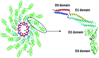
When proteins are used for functionalization, a unique and interesting possibility is the application of genetically modified flagellins or flagellar filaments assembled from engineered flagellin subunits. Several bacteria swim by rotating their flagellar filaments which are composed of thousands of flagellin monomers.44 The molecular weight of Salmonella flagellin is 51.5 kDa and it contains 494 amino acids. The monomeric flagellin consists of four domains (D0–D3) (see Fig. 1).45
 |
| Fig. 1 The cross section of flagellar filament (left) and the flagellin monomer with it's domains (right). The D3 domain is positioned at the surface of the flagellar filament, while the D0 and D1 domains are embedded inside the filament. | |
The hypervariable segment of the 190–284 amino acid sequence builds up the D3 domain, which has no significant role in the construction of the flagellar filament.46 Importantly, this domain, which is situated on the surface of flagellar filaments, can be modified by genetic engineering to give various functions to the monomeric flagellin and to the assembled flagellar filaments (Fig. 1). Note, salting out solutions containing ammonium sulfate can induce the self-assembly of flagellin monomers to form flagellar filaments in vitro. In this case short filament segments (“filament seeds”) are formed which can continue polymerizing even without ammonium sulfate.47 For example, the flagellin-GFP48 and flagellin-enzyme fusion (flagzyme) constructions49 were already reported. The flagellin can also be modified for analyte affinity sensing, flagellin based binding proteins and related filaments were constructed too.50–52 Flagellar filaments built up from engineered flagellins can be decorated by various nanoparticles.53,54 Functionalized flagellar filaments open up interesting new possibilities in in vivo biomineralization studies as well.14
There were already some attempts to incorporate the protein flagellin into surface coatings, but former research mainly focused on the inclusion of the filamentous form into thick multilayers.14 The works using flagellin monomers could only obtain monolayers of surface deposited flagellins.55,56 In one example, the functionalization of flagellar filaments was achieved by engineering the flagellin to display specific peptide loops on the filament's surface.14 Using these loops and the streptavidin–biotin interaction, multilayers of the filaments were assembled on gold surfaces coated with a self-assembled monolayer. In the same work, glutamic acid–aspartic acid peptide loop displaying filament nanotubes were assembled into multilayers using electrostatic interactions and a polyelectrolyte intermediate layer, namely polyethyleneimine. The authors concluded that the layer-by-layer self-assembly employing electrostatic attraction yielded a more uniform layer than the one obtained with the molecular complementarity of the biotin–streptavidin pair. Moreover, using aspartic acid and glutamic acid residues the in vivo mineralization of CaCO3 on the surface of the assembled filaments was first demonstrated by the group of Tripp and Muralidharan.14
In a previous publication, we have studied the surface deposition of flagellin monomers on hydrophilic and hydrophobic coatings using Optical Waveguide Lightmode Spectroscopy (OWLS).55 It was found that flagellin did not adsorb on hydrophilic surfaces, but rapidly formed a dense monolayer on hydrophobic coatings. Moreover, analyzing the optical anisotropy of the layers and using truncated flagellin variants we concluded that flagellin adsorbs on the hydrophobic surfaces through its disordered terminal regions, and the obtained monolayers are highly ordered.55 Schilardi and co-workers confirmed these findings, but investigated the monolayer formation on conductive Au(111) surfaces. They have also shown that the assembled flagellin monolayers are conductive and allow the allocation of electrochemically active cytochrome C.56
In the present work, we investigated the alternating deposition of the negatively charged flagellin and a positively charged synthetic polyelectrolyte (PAH, poly(allylamine) hydrochloride) in order to create composite nanostructured multilayers incorporating flagellin. Solutions containing flagellar filaments, flagellin monomers with seed particles; and pure flagellin solution will be systematically used during the deposition experiments. Optical measurements, using the surface sensitive Optical Waveguide Lightmode Spectroscopy (OWLS), and Atomic Force Microscopy (AFM) will be employed to follow the self-assembly processes in real time and to characterize the surface structures of the fabricated films. A new type of linearly growing polyelectrolyte multilayer buildup mechanism will be introduced, when one of the film forming components (namely PAH) induces the self-assembly of the oppositely charged component (flagellin monomers) into nanofilaments, creating a composite nanostructured filamentous film.
Experimental
Positive polyelectrolytes
Poly(allylamine) hydrochloride (PAH) was purchased from Alfa Aesar (Johnson Matthey Company, Budapest, Hungary) (cat. no. 43092, MW = 120
000–200
000 g mol−1). Poly-L-lysine (PLL) (MW = 150
000–300
000 g mol−1) solution 0.1% (w/v) in H2O and poly(diallyldimethylammonium chloride) (PDDA) (MW = 200
000–350
000 g mol−1) solution 20 wt% in H2O were purchased from Sigma Aldrich. The PAH, PLL and PDDA polymers were finally dissolved in 5 mM HEPES (Sigma, Budapest, Hungary) containing 50 mM KCl (Reanal, Budapest, Hungary), pH 7.4 at a final concentration of 0.5 mg mL−1.
Negative polyelectrolytes
Flagellar filament samples were prepared as reported earlier,45 but here 1.0 M AS was used for polymerization of the purified monomers. The filaments were collected by high speed centrifugation at 40
000 rpm for 60 min and dissolved in HEPES buffer. The thermally treated filament sample was prepared by keeping this solution in a hot bath at 70 °C for 20 minutes. The solution containing monomeric flagellin was obtained by filtering the thermally treated sample by further centrifugation (Biofuge pico, Heraeus) at 10
000 rpm using a centrifugal filter (Sigma-Aldrich, Amicon ultra 0.5 mL centrifugal filter, Z677906-24EA) with 100 kDa cut off. The 41 kDa truncated flagellin variant (F41), missing the disordered terminal regions of the molecule was prepared as reported earlier.57 A final protein concentration of 2 mg mL−1 was used in all of the experiments. The quality of the purified samples was checked by sodium dodecylsulfate–polyacrylamide gel electrophoresis (SDS–PAGE).
Dynamic light scattering measurements
The flagellar filament, thermally treated filament and the thermally treated and filtrated solutions were all analyzed by dynamic light scattering (DLS) using a Zetasizer Nano ZS instrument (Malvern Instruments, Malvern, UK) at 25 °C. Samples were measured in 10 mM HEPES buffer (pH 7.4) containing 100 mM KCl using 120 μL disposable polystyrene cuvettes. For each sample, five parallel size measurements were carried out and the mean of the five measurements was calculated. Data were analyzed using the DTS (Version 5.02) software supplied by Malvern.
Optical waveguide lightmode spectroscopy
An OWLS210 instrument (MicroVacuum Ltd., Budapest, Hungary) was used to follow the layer buildup in real time. OWLS is a surface sensitive technique employing planar optical waveguide chips. Here, glass supported TiO2–SiO2 waveguides (ASI2400 μV, Mikrovacuum Ltd., Budapest) were employed in all experiments. These waveguides support two optical modes with orthogonal polarizations (TE0 and TM0), which are excited by a He–Ne laser beam illuminating a 1 mm wide shallow grating embossed at the top of the waveguides. OWLS uses evanescent optical waves to probe refractive index variations in the close vicinity of the sensor surface (in a probing depth of around 100 nm).58–60 A flow through cuvette equipped with a septum injection port at the top of the waveguide was used to apply various solutions.61 The OWLS scanner recorded the effective refractive indices of the TE0 and TM0 waveguide modes during the assembling process with a time resolution of 13 s. From these values the adsorbed surface mass density was calculated using the Feijter's formula.62
Sensor chip cleaning
Prior to experiments the OWLS sensor chips and the glass slides were immersed in chromosulfuric acid for 3 minutes. This was followed by a short immersion in ultrapure water and 0.5 M KOH. After that, the chips and glass slides were intensively washed in ultrapure water for at least 30 minutes and dried in nitrogen flow.
Atomic force microscopy
Following the OWLS experiments the sensor surfaces were visualized by an AIST-NT Digiscope 1000 AFM instrument. Samples were scanned in non-contact mode, because this mode enables to investigate biological materials without damaging the sample. The PAH–flagellin composite layers were investigated by AFM after every deposition steps. In these cases, microscope slides were used for depositing the films.
Deposition protocols
All deposition started with a baseline recording by filling up the OWLS cuvette with pure buffer. The buffer was running at a constant flow speed of 1 μL s−1 using a REGLO Digital peristaltic pump (Ismatec, Wertheim, Germany) and relevant tubing equipped with a septum needle.61 The filament and flagellin solutions were applied through the septum injection port of the OWLS cuvette using a syringe equipped with a septum needle (Instech SN22/BULK50, VAH septum needles). In all cases 0.1 mL solution was injected. After 5 minutes, each sample injection was followed by a continuous buffer flow lasting for 5 minutes. The film depositions on the cleaned microscope slides were performed by immersing the slides into sterile eppendorf tubes containing the PAH, protein or buffer solutions. All immersion times were 5 minutes to mimic the conditions of the OWLS experiments.
Results and discussion
Particle size distribution of the applied flagellin solutions
The results of the dynamic light scattering measurements using the flagellar filament, thermally treated filament and the thermally treated and filtrated filament solutions are shown in Fig. 2. It is seen that the recorded intensity curve contains only a single sharp peak for the thermally treated and subsequently filtrated solution positioned at around 10 nm (Fig. 2a). Since DLS is extremely sensitive for aggregates (the scattered intensity is proportional to the sixth power of particle size), the single peak indicates that this solution contains flagellin monomers only. Note, this is reasonably expected after the thermal treatment and the application of the centrifuge filter with 100 kDa cutoff. It is important to emphasize that this monomer peak was stable, no filament formation (peaks at larger sizes) was observed even after days. The above mentioned monomer peak is also present for the thermally treated filament solution, but in this case, other peaks positioned at larger sizes are present, too. This feature indicates that after thermal treatment a small fraction of flagellin aggregates or short filaments are still present in the sample. The estimated amount of this non-monomeric component is less than 2% based on the volume distribution profile (Fig. 2b). For the original flagellar filament solution only intensity peaks at much larger sizes are measured (see Fig. 2a).
 |
| Fig. 2 The results of the dynamic light scattering experiments using the various flagellin solutions (a) intensity distribution of the flagellar filament, thermally treated and thermally treated and filtered flagellar filament solutions (b) volume size distribution of the thermally treated flagellar filament solution. The very small peak (see its enlargement in inset) next to the peak of flagellin monomers indicates the presence of some aggregates in the sample. | |
Composite films formed by alternating deposition of PAH and flagellar filaments
During the first coating experiment the subsequent depositions of PAH and flagellar filaments were followed. Altogether five deposition cycles were employed. One deposition cycle consisted of four subsequent steps: (i) applying the PAH solution over the surface for 5 minutes, (ii) rinsing the surface with buffer for 5 minutes, (iii) applying the negatively charged polyelectrolyte solution (now the flagellar filament solution) and finally, (iv) rinsing the surface with buffer solution for 5 minutes (see Fig. 3a). The results of the in situ OWLS experiment and the AFM measurement conducted after the OWLS are shown in Fig. 3. It is seen that the initially deposited PAH formed an irreversibly bound stable layer in a relatively short time. Washing with pure buffer did not remove any PAH from the surface of the OWLS chip. A significant amount of flagellar filament could be deposited onto the PAH layer, the deposition process saturated in 5 minutes. The formed layer was only partially removed by washing with buffer. It is interesting to note that the PAH solution applied after the flagellar filament deposition removed more flagellar filaments than what was the amount of the newly deposited PAH, since the recorded surface mass density clearly decreased (see Fig. 3a). This effect was even more pronounced after the first deposition cycle.
 |
| Fig. 3 (a) The deposited surface mass density during the alternating deposition of PAH and flagellar filaments, measured real time by OWLS. (b) AFM image of the PAH–flagellar filament composite film recorded after the 5th deposition cycle. | |
We believe, however, that at least some parts of the flagellar filaments were covered by newly deposited PAH during exposing the layer to the PAH solution; since the subsequent application of the flagellar filament solution resulted in a significant increase in deposited mass. It is clearly visible that for later deposition cycles, again, a significant amount of flagellar filament was deposited, but most of it was removed by washing with pure buffer and PAH solutions. The deposited net amount was less and less for the subsequent deposition cycles (see Fig. 3a). AFM images recorded after the OWLS experiment show that the obtained coating is rather inhomogeneous, loosely packed, the flagellar filaments assembled mainly into bundles (see Fig. 3b). These bundles are most probably hold together by the PAH molecules adsorbed on the surface of the filaments with electrostatic and hydrophobic interactions.
Composite coatings of PAH and thermally treated flagellar filaments
A significantly different behavior was observed when the previous experiment was repeated, but the flagellar filament solution was thermally treated prior to the deposition experiment. The employed thermal treatment disassembles the flagellar filaments and a solution of flagellin monomers and some aggregates of short filaments is obtained (see Fig. 2). Note, these aggregates can function as seeds for initiating filament polymerization. In this case the net deposited amount increased linearly for up to five deposition cycles. Again, the PAH exposure removes more material than the amount of the newly deposited PAH. It is interesting to note that both the newly deposited flagellin mass and the removed amount by the buffer and PAH solutions are increasing with increasing cycle number (see Fig. 4a). The linearly growing buildup is clearly visible in the inset of Fig. 4a where the deposited amount is plotted after the flagellin deposition steps for every deposition cycle. Of note, similar behavior was observed for a polyelectrolyte – nanoparticle system.41 The AFM images recorded after the OWLS experiment show a completely different surface structure than what was observed when intact flagellar filaments were used. Now, the deposited layer is more compact, a complex and dense filamentous network is clearly visible (see Fig. 4b). Supposing an averaged layer refractive index of 1.4 the estimated averaged film thickness at the end of the deposition process using the Feijter equation62 is around 60 nm. However, it should be noted that at this thickness range the OWLS technique underestimates the deposited surface mass density,63 therefore the true averaged thickness is probably even larger. Comparing this value with the diameter of flagellar filaments (23 nm),45 one can conclude that at these conditions multilayers were formed.
 |
| Fig. 4 (a) The deposited surface mass density during the alternating deposition of PAH and thermally treated flagellar filaments; measured real time by OWLS. Inset: the linear fit is shown as straight line for the deposited amount after each flagellin injection. The fit resulted in a slope of 483.8 ± 26.6 ng cm−2. (b) AFM image of the PAH-thermally treated flagellar filament composite film recorded after the 5th deposition cycle. | |
Our DLS experiments indicated that the thermally treated solution contains flagellin monomers and a very small fraction of flagellin aggregates or short filaments. These short filaments can function as seeds by inducing the polymerization of the flagellin monomers and can explain the formation of the observed filamentous multilayer. It is not clear from these experiments, however, whether the PAH has any influence on flagellin polymerization and whether PAH itself can induce the polymerization of the flagellin monomers or not. Therefore, an additional deposition experiment was also conducted using monomeric flagellin solution deprived of any aggregated material. This solution was obtained by filtering out the short aggregated filament seeds with a 100 kDa centrifugal filter. The molecular mass of flagellin is ∼51 kDa, while a very short filament including at least a complete turn along the 1-start helix consists of more than 11 subunits (∼560 kDa).
Composite coatings assembled by alternating deposition of PAH and monomeric flagellin
It was quite revealing to see that when filament seeds were filetered out from the thermally treated solution, the buildup was quite similar to what was observed in the experiment with thermally treated flagellar filaments. The linearly growing nature is clearly visible in this case, too (see Fig. 5). Several important features should be highlighted. Most importantly, PAH itself was able to induce the polymerization of flagellins into flagellar filaments within the formed surface layer. Even a single layer of PAH was sufficient to induce polymerization. This is clearly visible in the AFM images recorded after every deposition steps in parallel control experiments on microscope slides (see Fig. 6). Secondly, the deposited net amount per deposition cycle is less than what was obtained in the previous experiment. Therefore, we conclude that the short filament seeds increased the deposited amount, possibly by overcoming the limiting slow rate of spontaneous nucleation induced by PAH. The inset of Fig. 5 shows the linear fit to the deposited amounts with deposition numbers. Of note, the PAH solution removes relatively more material from the surface than in the previous type of experiment (see Fig. 4). This supports the above hypothesis that the filament seeds help to stabilize the film. After the 5th deposition cycle, again, a rather densely packed filamentous film was obtained (see Fig. 6). One can conclude that the PAH induces the nucleation of flagellin monomers, possibly by facilitating high local monomer concentration. The surface of the fabricated film gets rougher with increasing deposition cycle number, but this tendency is saturating at around a root mean square value (RMS) of 4 nm (see Fig. 7). However, when comparing this roughness of the surface to the estimated averaged thickness of layers from the OWLS data (22 nm) one can conclude that the fabricated coating is relatively smooth. The deposition mechanism fills in holes inside the deposited film, possibly by adsorption of PAH, followed by flagellin nucleation and polymerization. This tendency is clearly visible in Fig. 6. OWLS was also ideal to investigate the stability of these films, since the measured surface mass should decrease if the layer disassembles. These preliminary investigations revealed that the films are stable until at least several hours.
 |
| Fig. 5 The deposited surface mass density during the alternating deposition of PAH and monomeric flagellin, measured real time by OWLS. The linear fit in the inset is shown as straight line for the deposited amount after each flagellin injection. The fit resulted in a slope of 154.2 ± 7.3 ng cm−2. | |
 |
| Fig. 6 AFM images recorded after every deposition steps of the PAH–monomeric flagellin composite layers. The formed flagellar filaments are clearly visible. P: PAH, F: flagellin. | |
 |
| Fig. 7 The surface roughness of the PAH–monomeric flagellin coatings determined by AFM measurements. | |
Control experiments using PLL and PDDA as positively charged polyelectrolyte
In order to illuminate the role of the positively charged polyelectrolyte, the above OWLS experiment was repeated by employing PLL and PDDA instead of PAH. PLL and PDDA are also positively charged at pH 7.4, since their pKa values are 10.5. It was revealing to see that none of these experiments resulted in a linearly growing film, observed for the PAH–flagellin assembly. Instead, the deposited surface mass density started to saturate after three deposition cycles for both the PLL–flagellin and PDDA–flagellin films. To show this behaviour, the deposited surface mass densities after every deposition cycle are plotted in Fig. 8. For comparison, the values for the PAH–flagellin alternating assembly is also shown. AFM images recorded after 5 deposition cycles well confirmed these findings. Although a tendency for filament formation was also perceived in these cases, none of these films had the dense filamentous morphology observed for the PAH–flagellin layer. Very few micrometer long filaments were seen in case of PDDA–flagellin and only loosely packed short filaments (approximately 100 nm in length) were observed for the PLL–flagellin assembly. We believe that these dissimilarities are in connection with the differences in the charge per polymer weight ratios of these polyelectrolytes. In all cases one monomer contains a positive charge, but the masses of the monomer units are 146.19 Da, 161.5 Da and 93.52 Da for PLL, PDDA and PAH, respectively.
 |
| Fig. 8 The surface mass densities after every deposition cycles for the PLL–flagellin, PDDA–flagellin, and PAH–flagellin alternating depositions. | |
Control experiments using truncated flagellin variants missing the disordered terminal regions
In order to reveal the role of flagellin polymerization during the self-assembling process, an additional deposition experiment using the F41 truncated flagellin variant was also performed. F41 misses largely the disordered terminal regions. Without these regions the proteins can not form flagellar filaments since the α-helical segments stabilizing the filaments by hydrophobic interactions are missing.64 The result of the performed OWLS experiment is shown in Fig. 9a. Clearly, the linearly growing nature of film formation is completely missing. F41 adsorbs on the PAH layer, but after the 1st cycle it can be almost completely removed by the subsequent washings with buffer and PAH solutions. These results illuminate some unique characteristics of the buildup of the PAH–flagellin composite film. First, the formation of flagellar filaments is necessary to stabilize the incorporated flagellins inside the layer. Secondly, the linearly growing buildup is a clear consequence of filament formation. Fig. 9b further stresses the differences between the PAH–flagellin and PAH–F41 self-assembling processes, showing the amount of deposited material as a function of deposition cycles.
 |
| Fig. 9 (a) The in situ surface mass density during the alternating depositions of PAH and F41, measured real time by OWLS. (b) The calculated surface mass density after every deposition cycles for the PAH–monomeric flagellin and PAH–F41 alternating depositions. | |
The recorded OWLS data using F41 also help to estimate the flagellin concentration inside the first layer of PAH. Roughly 230 ng of F41 adsorbed in this layer per cm2. Note, this value is approximately 20% larger than the monolayer surface coverage of a densely packed oriented flagellin film.55 Supposing a film thickness of 10 nm, this value means a rather high protein concentration of 2.3 g mL−1. Therefore, it is not surprising at all that flagellins are forced very close to each other by PAH (Fig. 9), triggering this way their nucleation and polymerization into flagellar filaments. This hypothesis is supported by the fact that filament formation was much weaker with PLL or PDDA which have a significantly smaller charge density as compared to PAH. Of note, the suggested mechanism is very similar to the salting out effect by ammonium sulfate,47 but in our case the effect is strongly surface localized.
Conclusions
During the alternating deposition of the negatively charged protein flagellin and a positively charged polyelectrolyte, PAH several discoveries were made. Most importantly, the present work first reveals a new type of linearly growing polyelectrolyte multilayer buildup mechanism, when one of the components induces the self-assembly of the oppositely charged component. When flagellin was applied in its natural filamentous form no distinct multilayer buildup was observed, the filaments assembled mainly into bundles. In contrast, when thermally treated filament solution or flagellin monomer solution was used, a systematic linearly growing buildup was seen and, relatively smooth and thick layers were fabricated. The structural investigation revealed that the flagellin monomers assembled into nanofilaments inside the multilayer and even a single layer of PAH could induce the self-assembly of filaments. Both the filament formation and the multilayer buildup were completely absent when the F41 truncated flagellin variant – missing the disordered terminal regions – was applied. Since these regions are necessary for filament assembly, we conclude that the linear growing nature of the coating is a clear consequence of the filament formation. Also, using F41 we could prove that monomeric flagellin is easily removed from the layer, filament formation is necessary to stabilize flagellins inside the composite coating. We also concluded that the fabricated films are relatively smooth, what is in close connection with the assembling mechanism, having a tendency of filling up possible holes. The supposed buildup mechanism of the PAH–flagellin composite film is visualized in Fig. 10.
 |
| Fig. 10 Schematic representation of the PAH–monomeric flagellin composite film buildup. The inset shows a filament starting PAH induced flagellin nucleation and subsequent polymerization. | |
The introduced composite coatings can find diverse applications in nanotechnology and in biomedical sciences, since the D3 domain of flagellin can be easily modified to express enzymatic, fluorescent or molecular binding properties at the surfaces of the filaments without affecting the filament forming capabilities of the flagellin monomers. The present work therefore opens up novel routes in the bottom-up fabrication of complex nanostructured coatings.
Acknowledgements
This work was supported by the OTKA NN117849 and K104726 grants, by the Momentum (“Ledület”) Program of the Hungarian Academy of Sciences and by the ERC_HU project of NKFIH.
References
- A. Dobrynin and M. Rubinstein, Prog. Polym. Sci., 2005, 30, 1049–1118 CrossRef CAS.
- T. Radeva, Physical Chemistry of Polyelectrolytes (Surfactant Science), 2001 Search PubMed.
- Q. H. Johannes Frueh, M. Gai and S. Halstead, in Polyelectrolytes Thermodynamics and Rheology, 2014, pp. 19–86 Search PubMed.
- A. V. Dobrynin, Curr. Opin. Colloid Interface Sci., 2008, 13, 376–388 CrossRef CAS.
- J. B. Matson, R. H. Zha and S. I. Stupp, Curr. Opin. Solid State Mater. Sci., 2011, 15, 225–235 CrossRef CAS PubMed.
- M. Mihai and E. S. Dragan, Colloids Surf., A, 2009, 346, 39–46 CrossRef CAS.
- T. Boudou, T. Crouzier, K. Ren, G. Blin and C. Picart, Adv. Mater., 2010, 22, 441–467 CrossRef CAS PubMed.
- G. Decher, Multilayer Thin Films: Sequential Assembly of Nanocomposite Materials, 2012 Search PubMed.
- R. V. Klitzing, Phys. Chem. Chem. Phys., 2006, 8, 5012–5033 Search PubMed.
- M. Schönhoff, J. Phys.: Condens. Matter, 2003, 15, R1781–R1808 Search PubMed.
- G. Decher, J. D. Hong and J. Schmitt, Thin Solid Films, 1992, 210/211, 831–835 Search PubMed.
- W. B. Stockton and M. F. Rubner, Macromolecules, 1997, 30, 2717–2725 CAS.
- J. Seo, J. L. Lutkenhaus, J. Kim, P. T. Hammond and K. Char, Langmuir, 2008, 24, 7995–8000 CrossRef CAS PubMed.
- M. T. Kumara, B. C. Tripp and S. Muralidharan, Biomacromolecules, 2007, 8, 3718–3722 CAS.
- J. Seo, P. Schattling, T. Lang, F. Jochum, K. Nilles, P. Theato and K. Char, Langmuir, 2010, 26, 1830–1836 CrossRef CAS PubMed.
- P. Kohli and G. J. Blanchard, Langmuir, 2000, 16, 4655–4661 CrossRef CAS.
- D. E. Bergbreiter and K.-S. Liao, Soft Matter, 2009, 5, 23–28 RSC.
- K. Ariga, J. P. Hill and Q. Ji, Phys. Chem. Chem. Phys., 2007, 9, 2319 RSC.
- M. Shimomura and T. Sawadaishi, Curr. Opin. Colloid Interface Sci., 2001, 6, 11–16 CrossRef CAS.
- S. Zhang, Mater. Today, 2003, 6, 20–27 CAS.
- S. Verma, R. Gokhale and D. J. Burgess, Int. J. Pharm., 2009, 380, 216–222 CAS.
- R. S. Tu and M. Tirrell, Adv. Drug Delivery Rev., 2004, 56, 1537–1563 CrossRef CAS PubMed.
- J. Borges and J. F. Mano, Chem. Rev., 2014, 114, 8883–8942 CAS.
- C. Porcel, P. Lavalle, V. Ball, G. Decher, B. Senger, J. C. Voegel and P. Schaaf, Langmuir, 2006, 22, 4376–4383 CAS.
- J. M. Garza, P. Schaaf, S. Muller, V. Ball, J.-F. Stoltz, J.-C. Voegel and P. Lavalle, Langmuir, 2004, 20, 7298–7302 CAS.
- E. Hu, J. Voegel and P. Schaaf, Growth, 2004, 20, 1980–1985 Search PubMed.
- P. Lavalle, C. Picart, J. Mutterer, C. Gergely, H. Reiss, J.-C. Voegel, B. Senger and P. Schaaf, J. Phys. Chem. B, 2003, 108, 635–648 Search PubMed.
- F. Boulmedais, V. Ball, P. Schwinte, B. Frisch, P. Schaaf and J. C. Voegel, Langmuir, 2003, 19, 440–445 CAS.
- M. Nirschl, M. Schreiter and J. Vörös, Sens. Actuators, A, 2011, 165, 415–421 CrossRef CAS.
- P. Schultz, D. Vautier, L. Richert, N. Jessel, Y. Haikel, P. Schaaf, J.-C. Voegel, J. Ogier and C. Debry, Biomaterials, 2005, 26, 2621–2630 CAS.
- A. Verma, R. Dixit and J. K. Pandit, J. Sci. Ind. Res., 2012, 71, 407–412 CAS.
- F. Boulmedais, B. Frisch, O. Etienne, P. Lavalle, C. Picart, J. Ogier, J.-C. Voegel, P. Schaaf and C. Egles, Biomaterials, 2004, 25, 2003–2011 CrossRef CAS PubMed.
- O. Etienne, C. Gasnier, C. Taddei, J. C. Voegel, D. Aunis, P. Schaaf, M. H. Metz-Boutigue, A. L. Bolcato-Bellemin and C. Egles, Biomaterials, 2005, 26, 6704–6712 CAS.
- O. Etienne, C. Picart, C. Taddei, Y. Haikel, J. L. Dimarcq, P. Schaaf, J. C. Voegel, J. A. Ogier and C. Egles, Antimicrob. Agents Chemother., 2004, 48, 3662–3669 CrossRef CAS PubMed.
- A. I. Neto, A. C. Cibrão, C. R. Correia, R. R. Carvalho, G. M. Luz, G. G. Ferrer, G. Botelho, C. Picart, N. M. Alves and J. F. Mano, Small, 2014, 10, 2459–2469 CrossRef CAS PubMed.
- G. G. S. Grant, D. S. Koktysh, B. Yun, R. L. Matts and N. A. Kotov, Biomed. Microdevices, 2001, 3, 301–306 CrossRef.
- A. Dierich, E. Le Guen, N. Messaddeq, J. F. Stoltz, P. Netter, P. Schaaf, J. C. Voegel and N. Benkirane-Jessel, Adv. Mater., 2007, 19, 693–697 CrossRef CAS.
- E. Leguen, A. Chassepot, G. Decher, P. Schaaf, J.-C. Voegel and N. Jessel, Biomol. Eng., 2007, 24, 33–41 CrossRef CAS PubMed.
- S. Mehrotra, D. Lynam, R. Maloney, K. M. Pawelec, M. H. Tuszynski, I. Lee, C. Chan and J. Sakamoto, Adv. Funct. Mater., 2010, 20, 247–258 CrossRef CAS PubMed.
- B. Peter, S. Kurunczi, D. Patko, I. Lagzi, B. Kowalczyk, Z. Rácz, B. A. Grzybowski and R. Horvath, Langmuir, 2014, 30, 5029405 CrossRef PubMed.
- R. Horvath, H. C. Gardner and J. J. Ramsden, Appl. Phys. Lett., 2015, 4927403 Search PubMed.
- X. Q. Liu and C. Picart, Adv. Mater., 2015, 1295–1301 Search PubMed.
- Y. H. Kim, S. H. Lee, J. Noh and S. H. Han, Thin Solid Films, 2006, 510, 305–310 CrossRef CAS.
- K. Namba and F. Vonderviszt, Structure, function and assembly of flagellar axial proteins, 2008 Search PubMed.
- K. Yonekura, S. Maki-Yonekura and K. Namba, Nature, 2003, 424, 643–650 CrossRef CAS PubMed.
- F. Vonderviszt, A. Muskotál, C. S. Seregélyes and A. Sebestyén, J. Mol. Biol., 2010, 403, 607–615 CrossRef PubMed.
- K. Wakabayashi, H. Hotani and S. Asakura, Biochim. Biophys. Acta, 1969, 175, 195–203 CrossRef CAS.
- Á. Klein, B. Tóth, H. Jankovics, A. Muskotál and F. Vonderviszt, Protein Eng., Des. Sel., 2012, 25, 153–157 CrossRef PubMed.
- V. Szabó, A. Muskotál, B. Tóth, M. D. Mihovilovic and F. Vonderviszt, PLoS One, 2011, 6, e25388 Search PubMed.
- S. Kurunczi, R. Horvath, Y. P. Yeh, A. Muskotál, A. Sebestýn, F. Vonderviszt and J. J. Ramsden, J. Chem. Phys., 2009, 130, 1–4 CrossRef PubMed.
- R. Brunner, E. Jensen-Jarolim and I. Pali-Schöll, Immunol. Lett., 2010, 128, 29–35 CrossRef CAS PubMed.
- J. W. Huleatt, A. R. Jacobs, J. Tang, P. Desai, E. B. Kopp, Y. Huang, L. Song, V. Nakaar and T. J. Powell, Vaccine, 2007, 25, 763–775 CrossRef CAS PubMed.
- W. Jo, U. Cheang and M. Kim, Nano Convergence, 2014, 1, 10 CrossRef.
- S. M. Mudalige Thilak Kumara and B. C. Tripp, Chem. Mater., 2007, 19, 2056–2064 CrossRef.
- N. Kovacs, D. Patko, N. Orgovan, S. Kurunczi, J. J. Ramsden, F. Vonderviszt and R. Horvath, Anal. Chem., 2013, 85, 5382–5389 CrossRef CAS PubMed.
- A. González Orive, D. E. Pissinis, C. Diaz, A. Miñán, G. A. Benítez, A. Rubert, A. Daza Millone, M. Rumbo, A. Hernández Creus, R. C. Salvarezza and P. L. Schilardi, J. Colloid Interface Sci., 2014, 433, 86–93 CrossRef PubMed.
- F. A. Samatey, K. Imada, F. Vonderviszt, Y. Shirakihara and K. Namba, J. Struct. Biol., 2000, 132, 106–111 CrossRef CAS PubMed.
- J. Vörös, J. J. Ramsden, G. Csúcs, I. Szendrő, S. M. De Paul, M. Textor and N. D. Spencer, Biomaterials, 2002, 23, 3699–3710 CrossRef.
- J. J. Ramsden, Y. M. Lvovb and G. Decher, Thin Solid Films, 1995, 254, 246–251 CrossRef CAS.
- R. Horvath and J. J. Ramsden, Langmuir, 2007, 23, 9330–9334 CrossRef CAS PubMed.
- N. Orgovan, D. Patko, C. Hos, S. Kurunczi, B. Szabó, J. J. Ramsden and R. Horvath, Adv. Colloid Interface Sci., 2014, 211, 1–16 CrossRef CAS PubMed.
- J. A. De Feijter, J. Benjamins and F. A. Veer, Biopolymers, 1978, 17, 1759 CrossRef CAS.
- C. Picart, C. Gergely, Y. Arntz, J.-C. Voegel, P. Schaaf, F. J. G. Cuisinier and B. Senger, Biosens. Bioelectron., 2004, 20, 553–561 CrossRef CAS PubMed.
- F. Vonderviszt, S.-I. Aizawa and K. Namba, J. Mol. Biol., 1991, 221, 1461–1474 CrossRef CAS PubMed.
Footnote |
† Electronic supplementary information (ESI) available: Self-assembly, flagellar filament, flagellin, polyelectrolyte, composite nanostructured film, OWLS. See DOI: 10.1039/c6ra19010c |
|
This journal is © The Royal Society of Chemistry 2016 |
Click here to see how this site uses Cookies. View our privacy policy here.