Facile sonochemical synthesis of highly dispersed ultrafine Pd nanoparticle decorated carbon nano-onions with high metal loading and enhanced electrocatalytic activity

Aasiya Shaikh and Smrutiranjan Parida*
Department of Metallurgical Engineering and Materials Science, I.I.T. Bombay, Mumbai, India-400076. E-mail: paridasm@iitb.ac.in; Tel: +91-22-2576-7643

Received 17th July 2016 , Accepted 29th August 2016

First published on 29th August 2016


Abstract

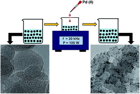
Highly dispersed, ultrafine Pd nanoparticle decorated carbon nano-onions (CNO) were prepared by a facile, one-step sonochemical method. The presence of surface functional groups and the mesoporosity of the as-prepared CNO helped achieve high nanoparticle dispersion at a high Pd loading with a marginal effect on the particle size under the sonochemical conditions. The Pd loading in the catalyst was varied as 18, 28 and 60 weight percent (wt%). The average size of Pd nanoparticles was around 2 nm up to 28 wt% loading and increases to 4 nm at 60 wt% loading. The electrocatalytic performance of Pd decorated CNOs were evaluated using formaldehyde oxidation in alkaline media. The electrochemically active surface area and the peak current density for formaldehyde electrooxidation increased with Pd loading up to 28 wt%. This suggests that the effect of metal loading dominates the particle size effect in CNO supported electrocatalysts if a high metal loading is achieved with a high degree of nanoparticle dispersion and better size control. The study also demonstrates that by selecting a suitable support material and controlling the synthesis conditions, the particle size and dispersion can be controlled while achieving high mass loading in an electrocatalyst.


1. Introduction

In recent years d-block metal nanoparticles have attracted much attention due to their excellent catalytic properties.1 Among these platinum and palladium metal nanoparticles show high electrocatalytic activity towards various electrochemical reactions.2–10 However, the high costs, large fluctuations in price, limited reserves and above all susceptibility to poisoning by reaction intermediates of Pt call for research into an alternative catalyst material. Pd is considered as a substitute for Pt11–13 for many reasons. Both Pt and Pd possess a similar electronic configuration, but the valence electrons (d-band) in Pd are less available for chemical interactions, which imparts an altogether different chemistry to Pd. Besides, Pd has a higher oxidation potential and inter-atomic bonds between Pd atoms are weak compared to Pt.14 Therefore, there have been continuous efforts to prepare Pd nanocatalysts in various morphologies and on various supports.14–17

Carbonaceous materials are the substrates of choice to support metal nanoparticles for applications such as catalysts and sensors.18–21 Carbon can exist in various allotropic forms, and it can also be prepared in various morphologies22 with the tunable surface area,23 pore size24 and electronic conductivity.25,26 The cost effectiveness, as well as ease of functionalization of carbon materials, are other advantages which help prepare carbon supported metal nanoparticles for various applications.27 In literature extensive research has been carried out to prepare supported metal nanoparticles on various carbon materials such as activated carbon (AC), carbon nanotubes (CNT), carbon nanofiber (CNF), mesoporous carbon and graphene.28–32 Carbon black (Vulcan XC-72) is widely used as a support for its specific high surface area. However carbon black suffers from few drawbacks such as mass transfer limitations due to its dense structure which prohibits formation of three phase boundary between gas, electrocatalyst and electrolyte.33 In case of CNT, metal dispersion on the inert graphitic basal plane surface requires functionalization using strong acids, which significantly reduces electrical conductivity of support. When graphene is used as support material, edge planes of graphene sheets offers suitable anchoring sites for the metal nanoparticles. However, restacking tendency of graphene sheets can limit the transport of reactant molecules.34

Recently, carbon nano-onions (CNO) are also being examined as a support material for nanoparticles.35 The unique morphology of CNO with concentric graphite rings and a large number of edge planes can be suitable sites for anchoring metal nanoparticles. Functionalization of the edge carbon atoms facilitates dispersion of metal nanoparticles and achieve high particle loading. In addition to that, a high metal nanoparticle loading can also be achieved in CNOs due to the mesoporous outer shells that are easily accessible. The sp2 carbon networks of CNOs are useful to enhance the charge-transfer processes in the catalyst.36,37 In catalyst and sensor applications, achieving ultrafine metal nanoparticles with good dispersion is key to the performance of supported nanoparticles.28 From the studies on other forms of carbon, various factors have been demonstrated to influence metal dispersion, such as the degree of functionalization,38 pore size distribution,39 the presence of sp2 carbon and above all the synthesis protocol.40

The CNOs can be synthesized by various methods, of which, thermal annealing of nanodiamonds has been widely used.37,41 However, in thermal annealing of nanodiamonds the separation of onion like carbon (OLCs) from initial diamond source pose a challenge to prepare a purer form of CNO, which requires continuous annealing at a high temperature greater than 1700 °C. Reactivity of CNOs obtained by this method is due to the structural defects on the outer graphitic wall,42 which are potential reactivity centers. Given the application potential of CNO in sensors and catalysts, finding an economical mass production method is essential. Recently, our group has reported a simple flame synthesis method for one-step synthesis of hydrophilic CNOs in bulk quantity.43 The advantage of such as-prepared CNO is that intermediate functionalization is not required for metal nanoparticles anchoring. Besides, BET study has revealed that these CNOs consist of a wide pore size distribution (2–60 nm) with pores in meso- and macro-porous range. The presence of meso- and macro-pores in a carbon support is ideal for better mass transport of the analyte and enhanced nanoparticle utilization.

Limited reports in the literature on the decoration of CNO with noble metal catalysts suggest that particle size and dispersion of the metal nanoparticle also depends on the source of CNO and impregnation method. Yasin et al. reported the Pd decoration of the CNO prepared by methane cracking, which are functionalized by p-phosphonic acid calix[8]arene. This decoration was carried out using a vortex fluidic device (VFD) and H2 gas as reducing agent, which resulted in the formation of Pd nanoparticles in 2–7 nm range depending on the vertex speed.44 Later Goh et al. also reported a similar method of Pt nanoparticle decoration of CNO, prepared by methane cracking process, using ascorbic acid as reducing agent, and claimed formation of nanoparticles as small as 3 nm.45 Later on an even simpler modification was reported where acid refluxed CNO was decorated with 2 nm Pt nanoparticles using H2 as reducing agent.35 This method resulted in Pt with different oxidation states indicating incomplete reduction of the precursor and as-prepared sample contained only 0.47 at% of metallic Pt. Authors also claimed that the average particle size of the Pt nanoparticles produced did not change even up to 100% loading. However, a significant Pt redox peak is visible only at 140% loading (7 μL of the precursor), which does not indicate better utilization of the supported Pt nanoparticles. The previous results suggest that functionalization of the CNO surface is necessary to create nucleation sites for metal nanoparticles. Santiago et al. reported Pt decoration of CNO obtained from thermal annealing of nanodiamonds by rotating disk-slurry electrode (RoDSE) technique.46 The authors reported the formation of Pt with various oxidation states due to incomplete reduction of Pt salt and only 37% of the total Pt formed was in the metallic state.

So far, all studies related to metal nanoparticle decorated CNO are confined to the structure and morphology of the composites produced. A detailed study of the electrochemical properties of the metal nanoparticle decorated CNO has not been carried out. Studies on the effect of metal loading on the particle size and its effect on the electrochemical properties are required to evaluate the CNO as a potential support material for metal nanoparticles.

The electrochemical activity of supported nanoparticles depends on the dispersion of metal nanoparticles on the carbon support. Various factors contribute to the dispersion, of which structure of the support and the method of dispersion play an important role. In applications requiring high metal nanoparticle loading, the effectiveness of the catalyst and catalyst utilization depend on the proper dispersion of metal nanoparticles on the support. When the metal loading is increased various structural, and electrochemical effects have been observed in the catalyst. Based on the work on various forms of carbon support it was observed that increase in the metal loading can lead to a decrease in catalyst mass activity,47,48 reduction in effective electrochemical surface area, a shift in the onset potential49 and increase in particle size.50 On the other hand, while studying the oxygen reduction reaction (ORR) on Pt–carbon black Higuchi et al.51 have reported that if the Pt dispersion state is optimized, then area-specific activity does not depend on the platinum loading (from ∼19 to ∼63 wt%). However, it must be emphasized that in all these studies a strong influence of the morphology and surface characteristics of the support as well as decoration method on the electrochemical activity is evident. Such kind of evaluation is lacking for the CNO supports, which is now analyzed and presented in this paper.

Here we report the synthesis of highly dispersed Pd nanoparticles decorated CNO catalysts prepared by a simple sonochemical method, without the use of any external reducing agent. High dispersion and high loading were possible due to hydrophilic nature, mesoporous structure of as-prepared CNO and sonochemical conditions. Compared to conventional methods for the synthesis of supported nanoparticles, the sonochemical method creates an ambient of free radicals and radical ions which are utilized in the reduction of metal ions.52 Thus, sonochemical method is a green procedure carried out at room temperature, which utilizes water as a solvent, avoiding the use of any hazardous reducing agent and stabilizers. The CNO supported nanocatalysts with Pd loading 18, 28 and 60 wt% were prepared by this method. A possible mechanism of formation of the Pd/CNO electrocatalyst under the sonochemical condition is proposed. The electrocatalytic activity of CNO supported Pd nanoparticles was investigated for formaldehyde electrooxidation in alkaline medium. A systematic study relating metal loading, nanoparticle size, and electrochemical performance were carried out.

2. Experimental

2.1. Chemicals and reagents

All chemical reagents were of reagent grade and were used without any further purification. Palladium acetate (C4H6O4Pd, 98%) was purchased from Sigma Aldrich. Formaldehyde (HCOH, 37%), sodium hydroxide pellets (NaOH), nitric acid (HNO3, 69%) and sulphuric acid (H2SO4, 95%) were purchased from Merck Millipore. DI water was used in all experiments at room temperature.

2.2. Synthesis of CNO and Pd/CNO nanocomposites

Water dispersible, functionalized CNOs with an average size of 45 nm were prepared by a simple flame synthesis method reported earlier.43 These CNOs were used in as-synthesized condition without any further modifications. The Pd decorated CNO nanoparticles were synthesized by a simple sonochemical method using a bath sonicator with operating frequency 20 kHz and 100 W power rating. Briefly, 20 mg of CNO was dispersed in 20 ml of deionized water and sonicated for one hour. Then, 25 ml of aqueous solution of the precursor palladium acetate was added gradually to the CNO dispersion, while sonication was going on. The whole process of gradual addition of the precursor took about 30 minutes. Given the power of the bath sonication and 30 minutes of reaction time, the corresponding energy supplied during nanocomposite formation is about 180 kJ. To prepare catalysts with various Pd loading, a precursor solution containing 5.6 mg (1 mM), 16.8 mg (3 mM) and 33.7 mg (6 mM) of palladium acetate was added. Finally, Pd decorated CNOs were separated by centrifuging the corresponding suspensions at 7500 rpm for 15 minutes followed by washing with deionized water and ethanol. The nanocomposites were dried overnight in an oven at 60 °C. After preparation, the actual loading of Pd in various nanocomposites were verified by thermo-gravimetric analysis, which confirmed the formation of Pd/CNO nanocomposites with 18 wt%, 28 wt% and 60 wt% Pd loading.

2.3. Physical characterization of Pd/CNO nanocomposite

The morphology and structure of Pd/CNO nanocomposites were characterized by high-resolution transmission electron microscope TecnaiG2, F30 (HR-TEM) with 2.0 angstrom point resolution, 1.0 angstrom line resolution and accelerating voltage of 300 kV. X-ray powder diffraction (XRD) patterns were obtained on a Philips X-Pert PRO X-ray diffractogram (XRD) with Ni-filtered Cu Kα radiation (λ = 1.5418 Å) in the range 2θ = 5–85°. Raman spectra were obtained using Horiba HR8000 spectrometer with excitation wavelength at 514.4 nm, 10 mV power and 30 seconds exposure time on 100× resolution. Thermal properties of Pd/CNO nanocomposite was studied by thermal gravimetric analysis (TGA) using Netzsch STA 449F3 Jupiter. Particle size was measured from the TEM micrographs using ImageJ software. Several areas of observation were used to obtain a good statistical accuracy. X-ray photoelectron spectroscopy (XPS) data were taken on an AXIS Supra instrument from Kratos Analytical in the range of 1–1200 eV to investigate the surface chemical composition.

2.4. Electrochemical measurements

A homogeneous suspension of Pd/CNO nanocomposites were prepared by adding 5 mg of the composite to 1 ml of ethanol followed by 1 hour bath sonication. Binder was not used in the formulation. 3 μl of the above suspension was drop cast on GCE and dried under IR lamp. Before immobilization of the Pd/CNO nanocomposite, GCE was activated by performing cyclic voltammetry at 100 mV s−1 in 0.5 M H2SO4 in potential window of −1 to +1 volt. All electrochemical experiments were performed at room temperature using an Autolab PGSTAT 308N electrochemical working station. All experiments were conducted using a three-electrode electrochemical cell consisting of modified GCE (diameter: 5 mm, area: 0.196 cm2) as working electrode, Hg/Hg2SO4 as a reference electrode and a platinum wire as counter electrode. All potentials in the present study were quoted versus Hg/Hg2SO4 reference electrode at room temperature. The electrocatalytic performance of Pd nanoparticle decorated CNO were studied in 0.3 M HCOH in 0.1 M NaOH solution by performing cyclic voltammetry at scan rates 25, 50, 75, 100, 150 and 200 mVs−1. All current values are normalized with respect to the geometrical area of the electrode.

3. Results and discussion

3.1. Mechanism of formation of Pd/CNO nanocomposites

The formation mechanism of the Pd nanoparticles on CNO under sonochemical condition can be explained by following mechanism, presented in Scheme 1. The ionization of Pd(CH3COO)2 precursor in aqueous solution produces Pd(II) and acetate ions. Sonolysis of water results in the formation of hydrogen radicals, which act as reducing agents and the reduction of Pd(II) ions to Pd(0) takes place. The gradual addition of the precursor during the preparation provided sufficient time for homogeneous distribution of Pd(II) ions on the CNO surface.
image file: c6ra18190b-s1.tif
Scheme 1 Mechanism of formation of Pd nanoparticles on CNO supports under sonochemical condition.

3.2. Characterization of the Pd/CNO nanocomposite

TEM micrographs of the Pd/CNO nanocomposites with different Pd loading are presented in the Fig. 1. The micrographs show a uniform distribution of Pd nanoparticles all over the surface of CNO support. The distributions of particle size, calculated from the micrographs, are also presented.
image file: c6ra18190b-f1.tif
Fig. 1 TEM micrographs and corresponding particle size distribution profile of the Pd/CNO nanocomposites with increasing Pd loading (A) 18 wt%, (B) 28 wt%, (C) 60 wt%.

The distribution indicates the average particle size varies as 1.8, 2.4 and 4.1 nm for 18 wt%, 28 wt% and 60 wt% Pd/CNO composites, respectively. It is important to note that the average particle size does not change significantly up to 28 wt% of Pd loading, and the distribution of particles is uniform. The high dispersion of Pd nanoparticles on the CNO support can be attributed to the surface functional groups present on the CNO nanoparticles, which act as anchoring sites for Pd nanoparticles. The presence of oxygen containing functional groups (–OH, –COOH, C[double bond, length as m-dash]O and –O–) were confirmed by XPS and FT-IR analysis of the as-prepared CNO support (Fig. 1SA–C, ESI). In addition to that gradual addition of the precursor during the preparation of the nanocomposites provided sufficient time for homogeneous distribution of Pd(II) ions on the support surface. At 60 wt% loading the average particle size increased to 4.1 nm with noticeable agglomeration of nanoparticles.

The high-resolution TEM (HR-TEM) micrographs of the CNO support and the nanocomposites with different Pd loading are presented in Fig. 2A–D. The CNO architecture is clearly discernible with characteristic concentric graphitic planes (Fig. 2A). The micrographs of the nanocomposites show ultrafine Pd nanoparticles distributed over the CNO architecture. Inter-planner distance measurement of Pd nanoparticles shows the formation of (111) facets with d(111) = 0.22 nm. However, some particles are formed with lattice fringes with inter-planner distance of 0.26 nm. This value of inter-planner spacing correspond to PdO (d(101) = 0.26 nm) nanoparticles.


image file: c6ra18190b-f2.tif
Fig. 2 HR-TEM micrographs of the support CNO and Pd/CNO nanocomposites with increasing Pd loading (A) CNO, (B) 18 wt%, (C) 28 wt% and (D) 60 wt%.

The X-ray diffraction of Pd/CNO nanocomposites and CNO are presented in Fig. 3 which gives a clear indication of the nanocomposite formation. The diffractogram of CNO support is presented by a broad peak at 24.38 corresponding to (002) graphitic plane of CNO. With the increase in the Pd loading the intensity of the characteristic (002) peak of the support is diminishing, indicating the formation of increasing number of Pd nanoparticles. At the same time, the characteristic diffraction peaks of Pd are also visible at 40.08, 46.62, 68.02 and 82.03 degrees corresponding to (111), (200), (220) and (311) planes of fcc phase of palladium (JCPDS 46-1043).53 An increase in the broadening of the prominent (111) peak for Pd is observed with the loading, indicating the decrease in the crystallite size. This observation along with the TEM (Fig. 1) suggests, with increase in loading, the larger particles are formed with smaller crystallite size. In agreement with TEM observation (Fig. 2), the diffraction peak of PdO is observed at 33.85°, corresponding to (101) plane of tetragonal phase of PdO (JCPDS 75-584).54 From the XRD the characteristic peak of PdO is getting prominent with an increase in the loading of palladium in the nanocomposite.


image file: c6ra18190b-f3.tif
Fig. 3 X-ray diffraction pattern of the CNO support and the Pd/CNO nanocomposites with various Pd loading.

The formation of PdO phases along with Pd(0) can be explained using the mechanism described in Scheme 2. It is possible that some of the Pd(II) ions were reacting with the activated water molecules, formed under the sonochemical condition, leading to the formation of an aquo-complexes. The aquo-complexes being unstable decomposed into PdO·H2O, which is converted to PdO after drying.


image file: c6ra18190b-s2.tif
Scheme 2 A mechanism of formation of PdO phase during Pd nanoparticle decoration on CNO support under sonochemical condition.

In our processing method, the sonication time is constant (30 min) at 100 W for all the Pd loadings. So the energy supplied may be not sufficient to reduce all PdO·H2O to Pd when the weight percentage of the precursor was increased. Therefore, the occurrence of PdO in the composites was increased with the increase in the Pd loading.

Fig. 4 shows Raman spectra of Pd/CNO nanocomposites and the pristine CNO. In Raman spectrum of CNO two intense bands are observed. One at 1583 cm−1 (G band) arises due to in-phase lattice vibrations, and another band at 1345 cm−1 (D band) is due to disorders present in the CNO.55


image file: c6ra18190b-f4.tif
Fig. 4 Raman spectra of the support and the Pd/CNO nanocomposites with different Pd loading.

In the case of Pd/CNO nanocomposites, the G band is slightly shifted towards high wavenumber (1594 cm−1) which is due to the strong bonding between Pd and CNO support and immobilization of metal nanoparticles on the surface of the carbon support.56 The intensity ratio ID/IG in Pd/CNO nanocomposite was lower than that of the carbon support. The decrease in the intensity ratios in Pd/CNO nanocomposite indicates generation of large number of smaller graphitic domains.57 This is another confirmation of development of chemical interaction and bond formation between the Pd nanoparticles and CNO support.58 In all composites a shoulder of G peak was observed at 1563 cm−1. This shoulder could be assigned to G peak arising due to the symmetry breaking of the tangential vibration when the graphitic sheets are curved. The G band is labelled to vibration modes with atomic displacement along the circumferential direction.59 This is more prevalent in CNT but can also appear in CNO with concentric graphite rings.

3.3. Electrochemical activity of Pd/CNO nanocomposites

Electrochemical activities of Pd/CNO nanocomposites were studied using formaldehyde oxidation in the alkaline medium. Fig. 5A represents cyclic voltammogram (CV) of all nanocomposites, CNO and bare GCE surface in 0.3 M HCOH in 0.1 M NaOH solution at 50 mVs−1.
image file: c6ra18190b-f5.tif
Fig. 5 (A) Cyclic voltammogram (CV) of bare GCE, CNO, and Pd/CNO nanocomposites in 0.3 M HCOH in 0.1 M NaOH at 50 mVs−1, (B) variation of the forward anodic peak current density with Pd loading in the nanocomposites.

The pristine CNO and the GCE do not show any current peaks for formaldehyde oxidation, which indicates that both GCE and pure CNO have no electrocatalytic activity towards formaldehyde oxidation. In the CV of all the nanocomposites, two distinct anodic peaks are observed in the forward and backward scan, respectively. There is no reduction peak in cyclic voltammogram indicating the oxidation of formaldehyde at Pd/CNO catalysts is an irreversible process.

The comparison of the peak current density of the forward anodic peak with Pd loading is presented in Fig. 5B. The peak current density of the forward anodic peak increased with Pd loading up to 28 wt% and then decreased about 20% for 60 wt% Pd loading. The increase in the peak current density up to 28 wt% loading is a clear indication of the loading effect, as the particle size increase in this range of loading is insignificant (Fig. 1). This is a significant observation due to fact that by careful selection of the support material and controlling the synthesis condition, the particle size and dispersion can be controlled while achieving high mass loading. Consequently, at a 28 wt% of Pd loading an optimum electrochemical activity towards electrooxidation of formaldehyde was achieved. The peak current density for the composite with 28 wt% Pd loading at 50 mVs−1 is 9.63 mA cm−2 (ca. 125 A g−1, based on the weight of the composite), which is higher than the reported values for formaldehyde electrooxidation by Pd-Vulcan XC-72 nanocomposite (1.2 A g−1) and Pd-MWCNT nanocomposite (5.6 A g−1).60

The increase in the loading beyond 28 wt% leads to about 20% decrease in the peak current density for 60 wt% Pd/CNO composite. The trend can be explained by the fact that, at 60 wt% Pd loading nanoparticles starts agglomerating and the average particle size increased to 4 nm, as confirmed by TEM observation (Fig. 1C). The agglomeration results in the reduction of the electro-active surface area. This suggests that at higher Pd loading the particle size effect dominates the loading effect, as the advantage of particle dispersibility and hence the effective surface area is lost. In addition to that, as observed from the XRD, the increase in PdO content with increase in loading from 28 to 60 wt% can be another reason for reduced catalytic activity, which is elaborated in the following section.

From the Fig. 5A the onset potential of formaldehyde oxidation are −0.035 V, −0.018 V and −0.014 V for 18 wt%, 28 wt% and 60 wt% Pd/CNO nanocomposites, respectively. The anodic shift indicates that as the Pd loading was increased in composite, it marginally increased (ca. 50 mV) the formaldehyde oxidation overpotential. Following the same trend, the peak potentials of the forward anodic peak in all composites also showed an anodic shift. The observed peak potentials were 0.137 V, 0.35 V and 0.3 V for 18 wt%, 28 wt% and 60 wt% Pd/CNO nanocomposites, respectively, at 50 mVs−1. These values of the peak potentials are comparable to the reported values for formaldehyde electrooxidation at various types of Pt and Pd electrodes.61

Fig. 6 shows cyclic voltammogram of all composites in 0.3 M HCOH in 0.1 M NaOH solution at different scan rates (a: 25 mVs−1 to f: 200 mVs−1). For a given Pd loading, CVs were taken in decreasing order starting from the highest scan rate, i.e. 200 mVs−1.


image file: c6ra18190b-f6.tif
Fig. 6 Cyclic voltammogram of Pd/CNO nanocomposites with increasing Pd loading in 0.3 M HCOH in 0.1 M NaOH showing the effect of scan rate (A) 18 wt%, (B) 28 wt%, (C) 60 wt%. Inset in each graph represents peak current density vs. square root of scan rate. The gradual increase in the slope is an indication the increase in the electro-active surface area up to 28 wt% Pd loading. For all graphs a: 25 mVs−1 to f: 200 mVs−1.

At all Pd loading, the peak current density of the forward anodic peak increased as the scan rate was increased. The inset graphs in each CVs shows the plot of forward peak current density against the square root of scan rate. All nanocomposites exhibited a linear relationship between peak current density and the square root of scan rate. This linear nature indicates that oxidation is a diffusion controlled process in this range of scan rates.62–64 For all the nanocomposites the peak potential increases with increasing scan rate indicating the formaldehyde electrooxidation is completely irreversible process.65

The long-term stability of the Pd/CNO electrocatalysts was investigated by repeated cyclic voltammetry for a large number of cycles. The anodic peak current density in the forward scan was measured for each cycle and was normalized to the initial value to obtain the percentage electrochemical activity retention. Fig. 7 shows the variation of the percentage activity retention with respect to the number of scans in 0.3 M HCOH + 0.1 M NaOH at 50 mVs−1. The Pd/CNO with 28 and 60 wt% showed similar cyclic stability with comparable electrochemical activity retention. The Pd/CNO with 18 wt% loading showed lesser electrochemical activity retention than the rest. For all Pd loading the electrochemical activity decreased with increasing number of scans. It is important to mention that, the binder was not used in preparing the Pd/CNO ink, which was drop cast onto the GCE. In the absence of the binder, the adhesion of the catalyst onto the GCE is purely physical in nature. In such case, the loss of catalyst from the electrode surface is possible. Therefore, the decreasing cyclic stability after a successive number of scans cannot be solely due to the loss of electrochemical activity. The catalyst debonding was also a contributing factor. Besides, the surface poisoning and gradual consumption of formaldehyde during the successive CV scans can also result in decrease in the peak current density.66


image file: c6ra18190b-f7.tif
Fig. 7 Electrochemical activity retention of Pd/CNO nanocomposites under continuous cycling at 50 mVs−1 in 0.3 M HCOH + 0.1 M NaOH solution.
3.3.1 The role of PdO on electrochemical activity. From the results of characterizations discussed before showed the presence of PdO to different degrees in all nanocomposites. We studied the role of PdO on the electrocatalytic activity of the nanocomposites. The best way to see such influence is to decompose the PdO thermally and observe the change in the activity of the composite. The catalyst with the highest amount of PdO (60 wt% Pd/CNO) was thermally heated in a TGA (heating rate = 10 °C min in the nitrogen atmosphere) experiment (Fig. 8). As shown in the plot the weight loss for pristine CNO after heating till 800 °C is only 12.9% which was due to the decomposition of various functional groups present at the surface of the carbon support. The 60 wt% Pd/CNO nanocomposite showed a small weight loss from room temperature to 190 °C and then sudden weight loss between 190 to 290 °C (15.6% weight loss). The weight loss between 190 to 290 °C can be accounted for conversion of PdO to metallic Pd nanoparticles and oxygen at the surface of the carbon support.54 The complete removal of the PdO from the 60 wt% Pd/CNO catalyst was confirmed by XRD data taken after TGA analysis (Fig. 8B). After the TGA, the PdO peak completely disappeared from the XRD.
image file: c6ra18190b-f8.tif
Fig. 8 (A) TGA of CNO and 60 wt% Pd/CNO nanocomposite showing decomposition of PdO to Pd, (B) XRD showing disappearance of PdO peak after thermal treatment, (C) electrooxidation of formaldehyde at 60 wt% Pd/CNO before and after thermal treatment in 0.3 M HCOH in 0.1 M NaOH (D) XPS spectra of as-prepared 60 wt% Pd/CNO composite in Pd 3d region.

The electrooxidation of formaldehyde for 60 wt% Pd/CNO before and after thermal treatment is presented in Fig. 8C. From the figure, the peak current density increased only about 9% after the complete reduction of the PdO in the nanocomposite. This increase in the peak current density of the forward anodic peak can be attributed to conversion of PdO to Pd during heating cycle resulting in the availability of more active sites (i.e. more palladium nanoparticles) for electrooxidation of formaldehyde. The role of the PdO was further explored by performing the XPS analysis of the as-prepared 60 wt% Pd/CNO composite (Fig. 8D). The XPS shows the presence of both PdO and Pd on the surface, with higher surface concentration PdO.67 The result confirms to the HR-TEM observation (Fig. 2), which shows the presence of Pd and PdO nanoparticles as isolated particles (with distinct lattice fringes) and distinct peaks for Pd and PdO in the XRD analysis (Fig. 3). Since XPS is a surface procedure, the peaks from PdO can be due to some Pd particles covered with PdO and from exclusive PdO nanoparticles. The Pd nanoparticles masked by PdO and exclusive PdO nanoparticles will show reduced catalytic activity, as PdO is not electroactive. Therefore, our findings suggest that, the decrease in the catalytic activity from 28 to 60 wt% Pd loading, can be due to both particle size effect and due to the formation of PdO-masked Pd and exclusive PdO nanoparticles.

4. Conclusion

In the present work Pd nanoparticles supported on CNO were synthesized by a simple and efficient sonochemical method using water as a solvent. This method avoids the addition of reducing agent and offers more uniform homogeneous dispersion of Pd nanoparticles with much smaller particle size. As the Pd loading on CNO was increased, the high particle dispersity was achieved with an insignificant increase in the particle size. TEM study showed the formation of ultrafine Pd nanoparticles uniformly dispersed on the CNO support. The electrocatalytic performance of Pd decorated CNO increases with Pd loading up to 28 wt% and further loading decreases the activity by 20%. The catalyst with 28 wt% of Pd loading shows optimum electrochemical activity with peak current 125 A g−1. The results showed that at CNO support, metal loading effect dominates the electrochemical activity if particle dispersion and the particle size are controlled. Achieving high mass loading with controlled particle size and a high degree of dispersion depends on the source of the CNO and the method of metal loading. The results also showed that Pd/CNO nanocomposite exhibit better electrocatalytic activity towards formaldehyde oxidation than Pd-MWCNT and have great potential for applications in other electrocatalytic reactions.

Acknowledgements

This work was supported by financial assistance from the Industrial Research and Consultancy Center (IRCC), IIT Bombay. The authors acknowledge access to the experimental facilities at Centre for Research in Nanotechnology & Science (CRNTS), IIT Bombay.

References

  1. B. R. Cuenya, Thin Solid Films, 2010, 518, 3127–3150 CrossRef CAS.
  2. I. Herrmann-Gepperta, J. Radnikb, U. I. Kramma, S. Fiechtera and P. Bogdanoff, ECS Trans., 2011, 41, 1161–1171 Search PubMed.
  3. J. Wu and H. Yang, Acc. Chem. Res., 2013, 46, 1848–1857 CrossRef CAS PubMed.
  4. J. Yin, S. Shan, M. S. Ng, L. Yang, D. Mott, W. Fang, N. Kang, J. Luo and C. J. Zhong, Langmuir, 2013, 29, 9249–9258 CrossRef CAS PubMed.
  5. L. Su, W. Jia, C.-M. Li and Y. Lei, ChemSusChem, 2014, 7, 361–378 CrossRef CAS PubMed.
  6. A. Stassi, I. Gatto, V. Baglio and A. S. Aricò, Int. J. Hydrogen Energy, 2014, 39, 21581–21587 CrossRef CAS.
  7. Z. Miao, D. Zhang and Q. Chen, Materials, 2014, 7, 2945–2955 CrossRef CAS.
  8. A. Krittayavathananon, P. Srimuk, S. Luanwuthi and M. Sawangphruk, Anal. Chem., 2014, 86, 12272–12278 CrossRef CAS PubMed.
  9. Y. Guo, Y.-T. Xu, G.-H. Gao, T. Wang, B. Zhao, X.-Z. Fu, R. Sun and C.-P. Wong, Catal. Commun., 2015, 58, 40–45 CrossRef CAS.
  10. A. Sarkar and A. Manthiram, J. Phys. Chem. C, 2010, 114, 4725–4732 CAS.
  11. C. Bianchini and P. K. Shen, Chem. Rev., 2009, 109, 4183–4206 CrossRef CAS PubMed.
  12. Q. Gao, M.-R. Gao, J.-W. Liu, M.-Y. Chen, C.-H. Cui, H.-H. Li and S.-H. Yu, Nanoscale, 2013, 5, 3202–3207 RSC.
  13. Z. Zhonghua, G. Junjie, M. Liang, L. Jianhui, L. Tianhong and X. Wei, Fuel Cells, 2009, 9, 114–120 CrossRef.
  14. H. Meng, D. Zeng and F. Xie, Catalysts, 2015, 5, 1221–1274 CrossRef CAS.
  15. M. L. Toebes, J. A. Van Dillen and K. P. De Jong, J. Mol. Catal. A: Chem., 2001, 173, 75–98 CrossRef CAS.
  16. A. Chen and C. Ostrom, Chem. Rev., 2015, 115, 11999–12044 CrossRef CAS PubMed.
  17. I. Saldan, Y. Semenyuk, I. Marchuk and O. Reshetnyak, J. Mater. Sci., 2015, 50, 2337–2354 CrossRef CAS.
  18. P. Trogadas, T. F. Fuller and P. Strasser, Carbon, 2014, 75, 5–42 CrossRef CAS.
  19. S. Shahgaldi and J. Hamelin, Carbon, 2015, 94, 705–728 CrossRef CAS.
  20. S. Sharma and B. G. Pollet, J. Power Sources, 2012, 208, 96–119 CrossRef CAS.
  21. H. Huang and X. Wang, J. Mater. Chem. A, 2014, 2, 6266 CAS.
  22. W. Sun, M. Chen, S. Zhou and L. Wu, Langmuir, 2014, 30, 12011–12017 CrossRef CAS PubMed.
  23. H. Liu, Y. Zhang, Q. Ke, K. H. Ho, Y. Hu and J. Wang, J. Mater. Chem. A, 2013, 1, 12962–12970 CAS.
  24. Z. Xiang-Qian, S. Qiang, D. Wei, L. Duo, L. An-Hui, M. Jian-Qing and L. Wen-Cui, J. Mater. Chem. A, 2013, 1, 9449–9455 Search PubMed.
  25. A. G. Pandolfo and A. F. Hollenkamp, J. Power Sources, 2006, 157, 11–27 CrossRef CAS.
  26. A. Hirsch, Nat. Mater., 2010, 9, 868 CrossRef CAS PubMed.
  27. K. Balasubramanian and M. Burghard, Small, 2005, 1, 180–192 CrossRef CAS PubMed.
  28. S. Wu, J. Liu, Z. Tian, Y. Cai, Y. Ye, Q. Yuan and C. Liang, ACS Appl. Mater. Interfaces, 2015, 7, 22935–22940 CAS.
  29. B. Wu, Y. Kuang, X. Zhang and J. Chen, Nano Today, 2011, 6, 75–90 CrossRef CAS.
  30. E. S. Steigerwalt, G. A. Deluga, D. E. Cliffel and C. M. Lukehart, J. Phys. Chem. B, 2001, 105, 8097–8101 CrossRef CAS.
  31. X.-H. Li and M. Antonietti, Chem. Soc. Rev., 2013, 42, 6593–6604 RSC.
  32. T. Gong, L. Qin, W. Zhang, H. Wan, J. Lu and H. Feng, J. Phys. Chem. C, 2015, 119, 11544–11556 CAS.
  33. M. Yaldagard, World J. Nano Sci. Eng., 2013, 3, 121–153 CrossRef CAS.
  34. K.-C. Pham, D. S. McPhail, C. Mattevi, A. T. S. Wee and D. H. C. Chua, J. Electrochem. Soc., 2016, 163, F255–F263 CrossRef CAS.
  35. H. Lu, P. K. Eggers, C. T. Gibson, X. Duan, R. N. Lamb, C. L. Raston and H. T. Chua, New J. Chem., 2015, 39, 915–920 RSC.
  36. H. W. Kroto, Nature, 1992, 359, 670–671 CrossRef.
  37. J. McDonough and Y. Gogotsi, Electrochem. Soc. Interface, 2013, 22, 61–66 CAS.
  38. J. R. C. Salgado, R. G. Duarte, L. M. Ilharco, A. M. Botelho do Rego, A. M. Ferraria and M. G. S. Ferreira, Appl. Catal., B, 2011, 102, 496–504 CrossRef CAS.
  39. E. Antolini and E. R. Gonzalez, Appl. Catal., A, 2009, 365, 1–19 CrossRef CAS.
  40. Y. Holade, N. Sahin, K. Servat, T. Napporn and K. Kokoh, Catalysts, 2015, 5, 310–348 CrossRef CAS.
  41. K. Makgopa, P. M. Ejikeme, C. J. Jafta, K. Raju, M. Zeiger, V. Presser and K. I. Ozoemena, J. Mater. Chem. A, 2015, 3, 3480–3490 CAS.
  42. A. Palkar, F. Melin, C. M. Cardona, B. Elliott, A. K. Naskar, D. D. Edie, A. Kumbhar and L. Echegoyen, Chem.–Asian J., 2007, 2, 625–633 CrossRef CAS PubMed.
  43. S. P. Debananda Mohapatra and S. Badrayyana, Mater. Chem. Phys., 2016, 174, 112–119 CrossRef.
  44. F. M. Yasin, R. a. Boulos, B. Y. Hong, A. Cornejo, K. S. Iyer, L. Gao, H. T. Chua and C. L. Raston, Chem. Commun., 2012, 48, 10102–10104 RSC.
  45. Y. A. Goh, X. Chen, F. M. Yasin, P. K. Eggers, R. A. Boulos, X. Wang, H. T. Chua and C. L. Raston, Chem. Commun., 2013, 49, 5171–5173 RSC.
  46. D. Santiago, G. G. Rodriguez-Calero, A. Palkar, D. Barraza-Jimenez, D. H. Galvan, G. Casillas, A. Mayoral, M. Jose-Yacaman, L. Echegoyen and C. R. Cabrera, Langmuir, 2012, 28, 17202–17210 CrossRef CAS PubMed.
  47. J. Perez, E. R. Gonzalez and E. A. Ticianelli, Electrochim. Acta, 1998, 44, 1329–1339 CrossRef CAS.
  48. L. Geniès, R. Faure and R. Durand, Electrochim. Acta, 1998, 44, 1317–1327 CrossRef.
  49. E. Hark, R. Jager and E. Lust, Electrocatalysis, 2015, 6, 242–254 CrossRef CAS.
  50. Y.-H. Cho, H.-S. Park, Y.-H. Cho, D.-S. Jung, H.-Y. Park and Y.-E. Sung, J. Power Sources, 2007, 172, 89–93 CrossRef CAS.
  51. E. Higuchi, H. Uchida and M. Watanabe, J. Electroanal. Chem., 2005, 583, 69–76 CrossRef CAS.
  52. J. H. Bang and K. S. Suslick, Adv. Mater., 2010, 22, 1039–1059 CrossRef CAS PubMed.
  53. Y. Zhao, X. Yang, J. Tian, F. Wang and L. Zhan, Int. J. Hydrogen Energy, 2010, 35, 3249–3257 CrossRef CAS.
  54. H. He and C. Gao, Molecules, 2010, 15, 4679–4694 CrossRef CAS PubMed.
  55. K. Szori, R. Puskás, G. Szollosi, I. Bertóti, J. Szépvölgyi and M. Bartók, Catal. Lett., 2013, 143, 539–546 CrossRef CAS.
  56. Y. Li, X. Fan, J. Qi, J. Ji, S. Wang, G. Zhang and F. Zhang, Mater. Res. Bull., 2010, 45, 1413–1418 CrossRef CAS.
  57. H. He and C. Gao, Sci. China: Chem., 2011, 54, 397–404 CrossRef CAS.
  58. Y. Lin, K. a. Watson, M. J. Fallbach, S. Ghose, J. G. Smith, D. M. Delozier, W. Cao, R. E. Crooks and J. W. Connell, ACS Nano, 2009, 3, 871–884 CrossRef CAS PubMed.
  59. A. Jorio, M. A. Pimenta, A. G. Souza Filho, R. Saito, G. Dresselhaus and M. S. Dresselhaus, New J. Phys., 2003, 5, 139 CrossRef.
  60. G.-Y. Gao, D.-J. Guo and H.-L. Li, J. Power Sources, 2006, 162, 1094–1098 CrossRef CAS.
  61. A. Safavi, N. Maleki, F. Farjami and E. Farjami, J. Electroanal. Chem., 2009, 626, 75–79 CrossRef CAS.
  62. V. Selvaraj, M. Alagar and K. S. Kumar, Appl. Catal., B, 2007, 75, 129–138 CrossRef CAS.
  63. B. Habibi and N. Delnavaz, Int. J. Hydrogen Energy, 2010, 35, 8831–8840 CrossRef CAS.
  64. Y. Chen, X. Liu, W. Zhang, Y. Zhang, L. Li, Z. Cao, H. Wang, G. Jia, Y. Gao and J. Liu, Anal. Methods, 2013, 5, 3915 RSC.
  65. S. Yang, X. Zhang, H. Mi and X. Ye, J. Power Sources, 2008, 175, 26–32 CrossRef CAS.
  66. V. Selvaraj, a. N. Grace and M. Alagar, J. Colloid Interface Sci., 2009, 333, 254–262 CrossRef CAS PubMed.
  67. X. Qiu, H. Zhang, Y. Dai, F. Zhang, P. Wu, P. Wu and Y. Tang, Catalysts, 2015, 5, 992–1002 CrossRef CAS.

Footnote

Electronic supplementary information (ESI) available. See DOI: 10.1039/c6ra18190b

This journal is © The Royal Society of Chemistry 2016
Click here to see how this site uses Cookies. View our privacy policy here.