Tannic acid stabilized silver nanoparticles for inkjet printing of conductive flexible electronics

Nan Zhang, Jing Luo*, Ren Liu and Xiaoya Liu
The Key Laboratory of Food Colloids and Biotechnology, Ministry of Education, School of Chemical and Material Engineering, Jiangnan University, Lihu Street 1800, Wuxi 214122, Jiangsu, China. E-mail: jingluo19801007@126.com; Fax: +86-510-85917763; Tel: +86-510-85917763

Received 5th August 2016 , Accepted 30th August 2016

First published on 30th August 2016


Abstract

In this study, we report a simple, environmentally-friendly, and economically scalable approach to synthesize silver nanoparticles (Ag NPs) which were prepared as conductive inks for fabricating electrically conductive patterns by direct inkjet printing. Using tannic acid (TA) as a reducing agent and capping agent simultaneously, the whole reaction was conducted in aqueous solution at room temperature in a very short time. The obtained TA-Ag NPs could be collected by precipitation and kept in solid form and stored without oxidation for several months, which greatly simplified the preparation steps and is quite beneficial for the storage and transportation. The as-prepared TA-Ag NPs have an average diameter of 15 nm and could be well dispersed in water to form a stable and homogenous silver ink. A conductive pattern can be achieved by inkjet printing the inks using a common color printer. The influence of the sintering temperature and print layers on the conductive performance of the printed silver pattern was investigated in detail and the sheet resistance of printed pattern decreased to 2 Ω □−1 at a sintering temperature of 200 °C. The printed silver pattern shows good adhesion towards the paper substrate under tape test. With the advantages of low cost, simple and green preparation, mass production, and high conductivity, this proposed method has great potential for application in printing flexible electronics, as demonstrated by the inkjet printing of conductive LED device circuits.
Introduction

Printed electronics have received considerable attention during the past few decades due to their wide applications, such as radio frequency identification (RFID) electronic tags, organic transistors, light emitting diodes (LEDs), and integrated circuits (IC).1–5 Among various printing techniques, inkjet printing has attracted increasing attention due to that it provides a digital, non-contact and maskless additive strategy to pattern on a wide range of substrate. In addition, it also possesses the advantages of cost-efficiency, material saving, simplicity, and scalability to large-area manufacturing. The key component in inkjet printing electronic patterns is the conductive material. Among the several studied conductive materials (metal NPs, metal precursors, carbon material, and conductive polymers), metal NPs are considered as the most promising candidate material for inkjet printing.6–13 Currently the most frequently used metal NP conductive inks are based on silver NPs owing to their high conductivity (∼105 S cm−1), strong oxidation resistance, and price (less expensive than gold).

A critical issue related to inkjet printing is the preparation of uniform and small Ag nanoparticles with good dispersibility, which is extremely important to obtain a highly stable conductive ink and fluent printing process. Ag nanoparticles with size of <20 nm are normally preferred as large nanoparticles or aggregation easily clog the printer nozzle which is detrimental to the inkjet printing process. Up to now, various methods have been developed to synthesize silver nanoparticles, including solvothermal reduction,14 microwave irradiation,15,16 chemical reduction,17,18 and microemulsion.19 Among them, chemical reduction method has been frequently employed to prepare silver nanoparticles owing to its advantages of mild synthetic conditions, low requirement of instruments, and convenience for large-scale production. In the chemical reduction method, silver nanoparticles are typically synthesized in solution via reduction of silver precursors in the presence of reducing agents and surface capping agents (stabilizer). However, the commonly used reducing agents such as sodium borohydride20,21 and hydrazine hydrate22 are toxic chemical reagents and are harmful to the environment. At the same time, hazardous organic solvents such as toluene, xylene and alkane, are normally used to prepare or disperse silver NPs.23,24 Recently, poly(acrylic acid) (PAA)25–28 and polyvinyl pyrrolidone (PVP)29,30 have been reported to stabilize silver nanoparticles in aqueous solution. But the synthetic procedure of silver NPs reported in these work is rather complicated as high-speed centrifugation was frequently required to collect the prepared silver NPs, which put a great limit for large scale production. Besides, the large quantity synthesis of silver nanoparticles (gram scale) in a short reaction time, which is a prerequisite for application in conductive ink, is still very scarce. Furthermore, the reported silver NPs for inkjet printing application were normally required to be in dispersion state for all the time to avoid any aggregation, which brings much trouble for storage and transportation. Also, extremely expensive professional printer (more than tens of thousands of dollars) is required to inkjet printing the silver NP into conductive patterns, which greatly raises the preparation cost. Therefore, new approaches with the advantages of nontoxic reducing agents, water phase reaction, minimal postprocessing, and economical scalability are in urgent need for the synthesis of small and uniform silver nanoparticles with good dispersibility and storage convenience for inkjet-printed flexible electronics.

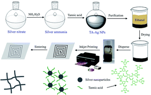
In this work, silver nanoparticles were synthesized with tannic acid (TA) as reducing agent and stabilizer simultaneously and prepared as conductive inks for fabricating electrically conductive patterns by direct inkjet printing using common color inkjet printer. Tannic acid (TA) is a natural, nontoxic, and biodegradable polyphenolic compound extracted from plant sources.31 The representative structure of tannic acid, corresponding to its average formula weight, is shown in Scheme 1. Possessing abundant catechol and pyrogallol units in its structure, TA is a natural reducing agent which is able to chelate with some metal ions and reduce them to metallic nanoparticles.32–36 In our synthetic route, TA not only reduced silver precursor, avoiding the usage of additional reducing agents or toxic reagents, but also served as capping agent and stabilizer for the in situ formed silver NPs. The whole reaction was carried out in an aqueous solution at ambient conditions, which is compatible with green chemistry principles. In addition, the reaction of silver ammonia with TA is quite efficient. A very short time (30 min) was needed to complete this reaction without the need of heating, which is thus ideal candidate for bulk production. Furthermore, the silver NPs could be collected easily by precipitation and drying without the need of centrifugation and could be kept in a solid form without oxidation over several months, which greatly simplifies the preparation steps and is quite beneficial for the follow-on applications. Silver NP inks for printing silver conductive patterns were prepared quickly by simply dispersing different quantities of silver NP powder in deionized water. Isopropanol was added to tune the surface tension of the silver NP inks to achieve good printability. Using a common color inkjet printer (less than three hundred dollars), the silver NPs inks were inkjet-printed onto photo paper and conductive patterns were obtained after thermal annealing.


image file: c6ra19800g-s1.tif
Scheme 1 Synthetic scheme of the preparation of TA-Ag NPs inks and its application in inkjet printing conductive flexible electronics.

Experimental

Chemicals

Silver nitrate (AgNO3), ammonia (NH3·H2O, 25–28%) and isopropanol (C3H8O) were purchased from Sinopharm Chemical Reagent limited corporation. Tannic acid (TA) was purchased from Shanghai Aladdin Chemical Reagents Company (China). All the chemical reagents were of analytical grade and used as received without further purification. The ultra-pure deionized water was used in all experiments.

Characterization

Structural characterization of TA-Ag NPs was carried out using UV-vis spectra on a TU-1901 spectro-photometer (Beijing Purkinje General Instrument Co., Ltd.) with a wavelength range of 200–700 nm. FTIR spectroscopic analyses were performed in reflection configuration with a Nicolet iS50 FT-IR spectrometer between 4000 and 600 cm−1. X-ray diffraction patterns (XRD) were carried on a Bruker AXS D8 Advance diffractometer with Cu Kα radiation (λ = 1.5406 nm). The thermal behavior of TA-Ag NPs was carried out using thermogravimetric analysis (TGA, Mettler Toledo 1100SF) with a heating rate of 10 °C min−1 under a nitrogen flow. The size and shape of TA-Ag NPs were observed through transmission electron microscope (TEM, JEOL JEM-2010). The viscosity of the inks was measured by viscometer (Discovery DHR-2) and the surface tension was examined through optical contact angle measuring instrument (OCA15EC). The microstructures of inkjet-printed conductive patterns were examined with an optical digital microscope (VHX-1000C) and scanning electron microscopy (SEM) (Hitachi S-4800). The resistance of the silver patterns was measured using a digital multimeter (Keysight 34401A) and the cross-section SEM images were analyzed to measure the thickness of printed patterns. Adhesion of the printed patterns to the photo paper substrate was assessed though a tape test.

Preparation of TA-coated silver NPs (TA-Ag NPs)

The preparation system employed silver ammonia as the silver source, tannic acid as the reducing agent and capping agent simultaneously, and the deionized water as the medium. The synthetic scheme of TA-Ag NPs was illustrated in Scheme 1. In a typical synthesis, 3.4 g of silver nitrate was dissolved in 50 mL of deionized water, followed by the dropwise addition of about 0.5 mL of ammonia solution into the mixture until the precipitate disappeared to prepare silver ammonia solution. Then 120 mg of tannic acid was dissolved in 50 mL of deionized water. After completion, the silver ammonia solution was added dropwise into the as-prepared TA solution at room temperature with continuous magnetic stirring for 30 min. The conversion of silver salt to silver nanoparticles was monitored by the change of the color over different reaction periods, which was observed to change from colorless, then yellowish, and final dark brown. After completion of the reaction, 500 mL of ethanol was added to the mixture solution (50 mL) to precipitate products and remove the excess TA and any by-products. TA-Ag NPs, which were formed as black precipitates, were collected in a beaker and dispersed in 10 mL of deionized water, then precipitated using 100 mL of ethanol again. After purification for 3 times, the black precipitates were collected and dried in an oven at 75 °C to obtain TA-Ag NPs.

Preparation of TA-Ag NPs ink

TA-Ag NPs inks with different solid contents were prepared by simply dispersing various amounts of TA-Ag NPs powder in deionized water. Considering that too large amount of TA-Ag NPs powder could not be dispersed well in deionized water, only TA-Ag NPs inks with solid content of 1–10 wt% were prepared. In order to achieve good printability, 25 vol% isopropanol was added to adjust the surface tension and viscosity of inks. After ultrasonic for 30 min, highly stable and homogenous TA-Ag NPs ink was obtained.

Inkjet printing and sintering of silver patterns

The TA-Ag NPs ink was injected into a clean ink cartridge and printed using a common color printer (Epson R330) on photo paper (Kodark). No pretreatment of photo paper was required. Silver patterns were printed with different layers on top of each other. During the printing process, the printed patterns were allowed in ambient conditions for 5 min between printing cycles. After the completement of all printing steps, the printed patterns were sintered at different temperatures within the range of 50–200 °C in a drying oven for 100 min.

It should be noted that one common problem during printing is the plugging of the nozzle of a printer, which is destructive for the inkjet printing process. To avoid any plugging of printing nozzles, TA-Ag NPs ink was filtered with a 0.45 μm filter to remove dust and larger silver clusters and injected into a clean ink cartridge before printing. After the printing process, pure ethanol was injected into ink cartridges and printed out for several time times to remove residual TA-Ag NPs ink and clean the nozzles of printer.

Results and discussions

Preparation and characteristics of TA-Ag NPs

Silver nanoparticles were synthesized by the reduction of silver ammonia with tannic acid as reducing agent and stabilizer simultaneously. Upon the addition of TA to silver ammonia solution, the color immediately changed from colorless to dark brown, indicating the reduction of silver ions. To follow the reaction process, the reaction mixture was monitored by the UV-vis adsorption spectra at different reaction periods. As shown in Fig. 1a, the Ag+ peak at about 300 nm disappeared immediately and a new peak for Ag NPs at about 400 nm shows up after the addition of TA, indicating the reduction of Ag+ by TA.37,38 Besides, it can be observed that the absorbance of Ag NPs gradually increased and then achieved balance in 30 min, suggesting the termination of the reduction reaction. In addition to the instinct peak at 400 nm, two shoulder peaks can be observed occurring at 210 and 280 nm, respectively, which just coincides with the characteristic peaks of TA, clearly evidencing the presence of TA in TA-Ag NPs. It was hypothesized that silver ions are first coordinated with the phenolic hydroxyl groups of tannic acid, which are then in situ reduced to zerovalent silver with the redox reactions of phenol to form quinones and donate electrons (the possible mechanism of reduction of silver ions with tannic acid was shown in Fig. S1).34 Then the neighboring zerovalent silver atoms aggregate to form silver nanoparticles which are stabilized by the catechol and oxidized quinine groups of TA molecules, leading to the formation of TA-Ag NPs. The steric hindrance and electrostatic repulsion of TA (TA bears negative charge at neutral solution) is believed to restrict the growth of the silver nanoparticles cooperatively. The whole preparation was carried out on a large scale in aqueous solution at ambient condition in a short time. 1.56 g of silver nanoparticles could be generated from 3.4 g of silver nitrate in a 100 mL reaction solution within 30 min. The synthesis of Ag NPs on a gram scale is a prerequisite for its applications in conductive ink.
image file: c6ra19800g-f1.tif
Fig. 1 (a) UV-vis spectra of TA, silver nitrate, silver ammonia and TA-Ag NPs under different reaction time, (b) FTIR spectra of TA and TA-Ag NPs.

To further confirm the presence of TA in the obtained Ag nanoparticles, the FT-IR spectrum of the prepared TA-Ag NPs was investigated and shown in Fig. 1b. The FT-IR spectrum of tannic acid was also provided for comparison. TA exhibits several absorption bands at 3300, 1697, 1605, 1527, 1443, 1310, 1184, 1087 cm−1, which are assigned to the stretching vibrations for O–H, C[double bond, length as m-dash]O, C[double bond, length as m-dash]C [(in-ring) aromatic] and C–C [(in-ring) aromatic], and bending vibrations for C–H [(in-ring) aromatic] and O–H, and stretching vibrations for C–O (esters, ethers), C–O (polyols), respectively. In the FTIR spectrum of TA-Ag NPs, these peaks were clearly observed suggesting the presence of TA in TA-Ag NPs. It should be noted that the shift of some peaks related to O–H, C[double bond, length as m-dash]O was observed for the FTIR spectrum of TA-Ag NPs compared to that of pure TA, indicating the interaction of TA with the surface of Ag-NPs through its carboxyl and hydroxyl groups.39

Fig. 2a shows the XRD patterns of synthesized TA-Ag NPs depending upon storage conditions. In the XRD measurement of freshly prepared TA-Ag NPs, five diffraction peaks at 2θ of 38.2°, 44.3°, 64.4°, 77.8° and 81.8° are attributed to the (1 1 1), (2 0 0), (2 2 0), (3 1 1) and (2 2 2) crystalline planes of silver, respectively. These characteristic peaks confirm the formation of a face-centered cubic silver phase (JCPDS no. 04-0783), indicating that silver nanoparticles were successfully prepared by tannic acid reduction. XRD characterization was also performed on the same samples exposed to ambient condition for 100 days. The XRD pattern exhibits almost the same characteristic peaks and no characteristic peaks of silver oxide is observed, suggesting that TA-Ag NPs are relatively stable against oxidation. Tannic acid has been studied extensively for its antioxidant properties.40 The good anti-oxidation ability of TA-Ag NPs is possibly attributed to the presence of TA capping layer at the surface of silver.


image file: c6ra19800g-f2.tif
Fig. 2 (a) XRD patterns of TA-Ag NPs, (b) TGA curves of TA and TA-Ag NPs.

The thermal analysis result of the TA-Ag NPs powder is presented in Fig. 2b. The sample shows a slight loss under 100 °C and a rapid weight loss between 150 to 600 °C. The little loss under 100 °C can be ascribed to the removal of small amount of water adsorbed on the surface of Ag NPs. The continuous weight loss from 150 to 600 °C is attributed to the decomposition of TA. After the equilibrium had been reached, the weight loss of TA-Ag NPs and TA is about 8% and 66.2%, respectively. As Ag NPs is stable under 800 °C, the silver content could be easily calculated from the TGA data and the TA-Ag NPs powder contained approximately 88 wt% silver.

Owing to the presence of TA, the obtained TA-Ag NPs could be easily dispersed in water without aggregation. Fig. 3 shows the TEM image (a) and size distribution (b) of TA-Ag NPs which was obtained by dispersing the solid powder in water. It can be clearly seen that the Ag nanoparticles are generally spherical in shape. The particle size distribution analysis demonstrates that the silver NPs are in the range of 8–22 nm with an average size about 15 nm. In addition, the TEM image and the size distribution of the TA-Ag NPs which have been stored for 100 days are quite similar to those of freshly prepared TA-Ag NPs. This good maintenance of the morphology and size distribution as well as the above-mentioned anti-oxidation capability endows an important advantage for TA-Ag NPs. The advantage is that the TA-Ag NPs could be easily stored in solid form for a long time at ambient conditions without aggregation or oxidation, which bring much convenience for its storage and transportation.


image file: c6ra19800g-f3.tif
Fig. 3 (a) TEM image and digital photograph (inset) of redispersed TA-Ag NPs, (b) particle size distribution of TA-Ag NPs.

The properties of TA-Ag NPs ink

Simply by redispersing the TA-Ag NPs powder in water, TA-Ag NPs ink was prepared. Before inkjet-printing of TA-Ag NPs ink, 25 vol% isopropanol was added to adjust the surface tension and viscosity of inks. It is well-known that surface tension and viscosity are two important physical properties of a printable ink which greatly influenced the behavior of the drops and jets. Fig. 4a shows the viscosity and surface tension of the developed TA-Ag NPs inks versus different silver content. It can be observed that with the increasing silver content of the TA-Ag NPs inks, both the viscosity and surface tension increased. The viscosity and surface tension of TA-Ag NPs ink increased from 1.3 mPa s to 3.71 mPa s and 34.97 mN m−1 to 36.83 mN m−1, respectively, as the silver content increased from 1 wt% to 10 wt%. It is noted that the surface tension values of 30–40 mN m−1 are in the appropriate range for inkjet printing of conductive inks.5 In addition to surface tension and viscosity, a long shelf life of conductive inks is also very important for their applications in inkjet printing. Fig. 4b shows the digital photographs of TA-Ag NPs inks with different solid content after placing for 2 weeks. It can be clearly seen that no aggregation or precipitation of TA-Ag NPs inks was observed in the later placement, which exhibited excellent dispersity and stability of TA-Ag NPs inks.
image file: c6ra19800g-f4.tif
Fig. 4 (a) Viscosity and surface tension of TA-Ag NPs inks, (b) digital photographs of TA-Ag NPs inks after placing for 2 weeks.

Besides the viscosity and surface tension, some other physical parameters, such as jet velocity (v), characteristic length (d) and density (ρ), could also affect the printability of TA-Ag NPs inks. The relative importance of these parameters could be characterized through the following three dimensionless numbers: the Reynolds (Re), Weber (We) and Ohnesorge (Oh) numbers:27

image file: c6ra19800g-t1.tif

image file: c6ra19800g-t2.tif

image file: c6ra19800g-t3.tif

Among them, Re and We are related to the spreading behavior of the ink and the inverse (Z) of the Oh determines the printability of TA-Ag NPs ink. In order to achieve good printability, the value of Z should be limited in the range of 1–10. In the case that the value of Z is higher than 10 or lower than 1, the ink could not be printed fluently.27,41 The Z values of TA-Ag NPs ink with different silver contents were calculated and the results are shown in Table 1. The value of Z deceased from 16.88 to 6.32 with increasing silver content, demonstrating that TA-Ag NPs ink with silver contents ranging from 2.5 to 10 wt% were printable according to the calculation results.

Table 1 Physical parameters of TA-Ag NPs ink with different silver contents (d = 14 μm)
Silver content Viscosity η (mPa s) Surface tension γ (mN m−1) Density ρ (×103 kg m−3) Z
1 wt% 1.3 34.97 0.984 16.88
2.5 wt% 2.24 35.42 1.005 9.95
5 wt% 2.92 35.77 1.030 7.77
10 wt% 3.71 36.83 1.067 6.32


Morphology and conductivity of silver patterns printed on photo paper

The prepared TA-Ag NPs ink is then inkjet printed on the photo paper using a common color inkjet printer. Various patterns could be created by inkjet printing system. As the inkjet printer is operated by personal computer, the patterns could be easily designed by CorelDRAW software. The line width of patterns could be set by the software and the thickness could be controlled by changing the solid concentration of conductive ink and the print layers of conductive patterns. In this procedure, as occasional plugging accidents occurred when higher ink concentrations (5 and 10 wt%) were employed for inkjet printing, TA-Ag NPs ink with relatively lower concentration (2.5 wt%) was used for inkjet printing to avoid any possibility of the nozzle plugging. At this concentration, the printer could work continuously for 12 h without any plugging. With the ink concentration being kept constant, the thickness of printed patterns only depends on the number of print layers.

Fig. 5 shows the digital and optical microscopy photographs of printed patterns. It can be observed that silver lines, squares, circles and RFID antenna patterns with different sizes were printed on photo paper. When the line width was set as 300 μm, the actual line width of printed line was 337 μm. In the case that circle radius was set as 500 μm, the radius of printed circle on photo paper was 535 μm. The larger printed line width than the setting ones was possibly attributed to the printer location error and the spreading of the ink on the photo paper.27


image file: c6ra19800g-f5.tif
Fig. 5 (a) Digital and (b and c) optical microscopy photographs of printed patterns.

The cross-section SEM images of the printed silver track on photo paper after curing at 200 °C with different printing layers were shown in Fig. 6. The thickness of the silver tracks increased with printing layers as more inks were deposited on the photopaper during printing. The thickness of the silver track for 10 print layers was measured to be about 1.6 μm. With the increasing print layers to 20, 30, 40, the thickness increased to 2.4, 2.9, and 3.2 μm, respectively.


image file: c6ra19800g-f6.tif
Fig. 6 Cross-section SEM images of the printed silver track on photo paper after curing at 200 °C with different printing layers. (a) 10 layers; (b) 20 layers; (c) 30 layers; (d) 40 layers.

To investigate the transition of the microstructures of the printed silver patterns during the sintering process, the silver patterns with 40 print layers on photo paper at different sintering temperature were examined by SEM. Fig. 7 shows the SEM images of printed silver patterns after heat curing for 100 min at 25 °C, 50 °C, 100 °C, 150 °C and 200 °C, respectively. As shown in Fig. 7a and b, the silver patterns after room temperature drying are composed of uniform and spherical Ag NPs which are not connected with each other. After annealing at 50 °C (Fig. 7c and d), there are only slight changes compared to the patterns heated at 25 °C. Some big clusters appeared after heat curing at 100 °C (Fig. 7e and f), indicating the aggregation of some Ag NPs. When the sintering temperature was increased to 150 °C, significant inter-particle sintering is observed from Fig. 7g and h. Most boundaries between particles disappeared due to sintering and the formation of continuous interconnections. With the sintering temperature further increase to 200 °C, nearly all the silver particles have fused with each other to form a network throughout the entire silver film and the printed silver pattern became smooth and continuous (Fig. 7i and j). Some cracks were formed on the surface of the track after sintering at 200 °C, which is possibly attributed to the residual thermal stress in the lines that accumulate upon cooling due to the different thermal expansion coefficients for silver tracks and the paper substrate.


image file: c6ra19800g-f7.tif
Fig. 7 SEM images of printed silver patterns at sintering temperature of (a and b) 25 °C, (c and d) 50 °C, (e and f) 100 °C, (g and h) 150 °C and (i and j) 200 °C.

Electrical properties of the sintered silver patterns

To study the electrical conductivity of the printed silver patterns, a digital multimeter (Keysight 34401A) was used to measure the sheet resistance. Fig. 8 shows the influence of sintering temperature, sintering time and number of print cycles on the electrical resistivity of the printed silver patterns on the photo paper.
image file: c6ra19800g-f8.tif
Fig. 8 Sheet resistance of printed silver patterns with different print layers (a), sintering temperature (b), and sintering time (c).

To investigate the influence of the print cycles on the electrical resistivity of the printed silver patterns, samples with 10, 20, 30, 40 print layers were prepared. Considering the complete coalescence of the silver particles at 200 °C from the analysis of above SEM images, all the samples were sintering at 200 °C. The relationship between sheet resistance of silver patterns and printing layers was shown in Fig. 8a. It can be observed that the number of print cycles plays an important role on the electrical properties of printed silver patterns. As the number of printing cycles increased from 10 layers to 40 layers, the sheet resistance decreased remarkably from 500 Ω □−1 to 2 Ω □−1. The further increase of printing cycles to 50 layers leads to a slight change of the sheet resistance, indicating that the equilibrium was reached. Therefore, 40 print cycles were adopted in the following experiment.

It has been observed from the SEM images (Fig. 7) that the sintering temperature has a great influence on the morphology of the printed silver patterns, which should directly affected the electrical properties of the samples sintered at different temperatures. As shown in Fig. 8b, the sheet resistance generally decreased with increasing the sintering temperature. For the silver patterns sintering at room temperature (25 °C), the sheet resistance was about 26 Ω □−1. After sintering at 50 °C, the sheet resistance is almost unchanged which is in accordance with the slightly changed morphology. As the sintering temperature was increased to 100 °C, the sheet resistance of the printed silver patterns slowly reduced to 17 Ω □−1. With the sintering temperature further increase to 150 °C, the sheet resistance of the printed silver patterns was remarkably decreased to 7 Ω □−1. This great decrease of sheet resistance just coincides with the significant inter-part sintering reflected by the morphology as shown in Fig. 7. The decrease of sheet resistance should thus be attributed to the interconnection between Ag NPs. When the silver patterns underwent sintering at 200 °C, the sheet resistance is only 2 Ω □−1, corresponding to the complete interconnection and coalescence of Ag NPs. In addition to sintering temperature, the sintering time also plays an important role on the electrical properties of printed silver patterns. The sheet resistance gradually decreased and a constant value was achieved until the sintering time reached 100 min (Fig. 8c).

To evaluate the applicability of TA-Ag NPs conductive ink, various silver patterns were printed onto photo paper and sintering at 200 °C for 100 min. The LED was integrated into a complete circuit with the printed silver patterns serving as the conducting wire, as shown in Fig. 9. The lighted LED demonstrated that the printed silver patterns could pass the LED test which possesses good performance towards printed electronics.


image file: c6ra19800g-f9.tif
Fig. 9 Digital photographs of LED test connected with printed silver patterns.

Mechanical properties of the sintered silver patterns

The good adhesion between the silver pattern and the substrate is a key problem in printed electronics. The adhesion of the sintered silver patterns was evaluated qualitatively by a simple tape test. A tape (Scotch tape, 3 M) was adhered to the silver patterns and then removed by peeling it off. The digital images of printed silver patterns before and after tape test were shown in Fig. S2 (ESI). It can be observed that the silver films stayed fairly well on the paper substrate after peeling off the tape and no evidence of delamination or structural change was observed, indicating good adhesion between the printed silver films and paper substrate.

Conclusion

In summary, a simple, green, and economically scalable approach was developed to synthesize silver nanoparticles for inkjet printing application. Using tannic acid (TA) as reducing agent and capping agent simultaneously, the whole reaction was conducted in aqueous solution at room temperature in a very short time, which is environmental-friendly and appropriate for mass production. Furthermore, the obtained TA-Ag NPs with average diameter of 15 nm could be kept in solid form and stored without oxidation for several months, which is quite beneficial for the storage and transportation. Highly stable and homogenous TA-Ag NPs inks were prepared by simply dispersing the TA-Ag NPs powder in water. Using this silver conductive ink, various conductive silver patterns were deposited on photo paper by inkjet printing using a common color printer. The resistivity of the silver patterns could be decreased to 2 Ω □−1 with sintering at 200 °C for 100 min. A potential use of the silver patterns as a conductive LED device circuits has been displayed. The printed silver pattern also shows good adhesion toward paper substrate under tape test. With the advantages of low cost, simple and green preparation, short processing time, mass production, and high conductivity, this proposed method has great potential application in printing flexible electronics.

Acknowledgements

We acknowledge financial support from the National Natural Science Foundation of China (under Grant No. 51573072), MOE & SAFEA for the 111 Project (B13025), Postgraduate Research Innovation Project (KYLX15-1179).

References

  1. V. Sanchez-Romaguera, S. Wünscher, B. M. Turki, R. Abbel, S. Barbosa, D. J. Tate and S. G. Yeates, J. Mater. Chem. C, 2015, 3, 2132–2140 RSC.
  2. J. F. Salmerón, F. Molina-Lopez, D. Briand, J. J. Ruan, A. Rivadeneyra, M. A. Carvajal, L. F. Capitán-Vallvey, N. F. de Rooij and A. J. Palma, J. Electron. Mater., 2014, 43, 604–617 CrossRef.
  3. K. Fukuda, T. Sekine, D. Kumaki and S. Tokito, ACS Appl. Mater. Interfaces, 2013, 5, 3916–3920 CAS.
  4. A. C. Siegel, S. T. Phillips, M. D. Dickey, N. Lu, Z. Suo and G. M. Whitesides, Adv. Funct. Mater., 2010, 20, 28–35 CrossRef CAS.
  5. T. T. Nge, M. Nogi and K. Suganuma, J. Mater. Chem. C, 2013, 1, 5235–5243 RSC.
  6. J. Jiang, B. Bao, M. Li, J. Sun, C. Zhang, Y. Li, F. Li, X. Yao and Y. Song, Adv. Mater., 2016, 28, 1420–1426 CrossRef CAS PubMed.
  7. M. Abulikemu, E. H. Da'As, H. Haverinen, D. Cha, M. A. Malik and G. E. Jabbour, Angew. Chem., 2014, 126, 430–433 CrossRef.
  8. M. Layani, M. Grouchko, S. Shemesh and S. Magdassi, J. Mater. Chem., 2012, 22, 14349–14352 RSC.
  9. A. Albrecht, A. Rivadeneyra, A. Abdellah, P. Lugli and J. F. Salmerón, J. Mater. Chem. C, 2016, 4, 3546–3554 RSC.
  10. Y. Zhang, P. Zhu, G. Li, T. Zhao, X. Fu, R. Sun, F. Zhou and C. Wong, ACS Appl. Mater. Interfaces, 2014, 6, 560–567 CAS.
  11. Y. C. Liao and Z. K. Kao, ACS Appl. Mater. Interfaces, 2012, 4, 5109–5113 CAS.
  12. D. Deng, Y. Jin, Y. Cheng, T. Qi and F. Xiao, ACS Appl. Mater. Interfaces, 2013, 5, 3839–3846 CAS.
  13. G. Wang, Z. Wang, Z. Liu, J. Xue, G. Xin, Q. Yu, J. Lian and M. Y. Chen, Chem. Eng. J., 2015, 260, 582–589 CrossRef CAS.
  14. J. Lai, W. Niu, R. Luque and G. Xu, Nano Today, 2015, 10, 240–267 CrossRef CAS.
  15. X. Zhao, Y. Xia, Q. Li, X. Ma, F. Quan, C. Geng and Z. Han, Colloids Surf., A, 2014, 444, 180–188 CrossRef CAS.
  16. P. Velusamy, C. H. Su, G. V. Kumar, S. Adhikary, K. Pandian, S. C. B. Gopinath, Y. Chen and P. Anbu, PLoS One, 2016, 11, e0157612 Search PubMed.
  17. A. Kosmala, R. Wright, Q. Zhang and P. Kirby, Mater. Chem. Phys., 2011, 129, 1075–1080 CrossRef CAS.
  18. Z. K. Kao, Y. H. Hung and Y. C. Liao, J. Mater. Chem., 2011, 21, 18799–18803 RSC.
  19. E. Nourafkan and A. Alamdari, J. Ind. Eng. Chem., 2014, 20, 3639–3645 CrossRef CAS.
  20. B. Baruah, G. J. Gabriel, M. J. Akbashev and M. E. Booher, Langmuir, 2013, 29, 4225–4234 CrossRef CAS PubMed.
  21. Z. Dong, X. Le, X. Li, W. Zhang, C. Dong and J. Ma, Appl. Catal., B, 2014, 158, 129–135 CrossRef.
  22. K. Do Kim, D. N. Han and H. T. Kim, Chem. Eng. J., 2004, 104, 55–61 CrossRef.
  23. K. Ankireddy, S. Vunnam, J. Kellara and W. Cross, J. Mater. Chem., 2013, 1, 572–579 CAS.
  24. X. Zhou, W. Li, M. Wu, S. Tang and D. Liu, Appl. Surf. Sci., 2014, 292, 537–543 CrossRef CAS.
  25. Q. Huang, W. Shen, Q. Xu, R. Tan and W. Song, Mater. Chem. Phys., 2014, 147, 550–556 CrossRef CAS.
  26. M. Layani, I. Cooperstein and S. Magdassi, J. Mater. Chem. C, 2013, 1, 3244–3249 RSC.
  27. W. Shen, X. Zhang, Q. Huang, Q. Xu and W. Song, Nanoscale, 2014, 6, 1622–1628 RSC.
  28. J. Perelaer, R. Jani, M. Grouchko, A. Kamyshny, S. Magdassi and U. S. Schubert, Adv. Mater., 2012, 24, 3993–3998 CrossRef CAS PubMed.
  29. J. Olkkonen, J. Leppäniemi, T. Mattila and K. Eiroma, J. Mater. Chem. C, 2014, 2, 3577–3582 RSC.
  30. Q. Huang, W. Shen and W. Song, Appl. Surf. Sci., 2012, 258, 7384–7388 CrossRef CAS.
  31. J. Luo, J. Lai, N. Zhang, Y. Liu, R. Liu and X. Liu, ACS Sustainable Chem. Eng., 2016, 4, 1404–1413 CrossRef CAS.
  32. J. Luo, N. Zhang, J. Lai, R. Liu and X. Liu, J. Hazard. Mater., 2015, 300, 615–623 CrossRef CAS PubMed.
  33. Y. Cao, R. Zheng, X. Ji, H. Liu, R. Xie and W. Yang, Langmuir, 2014, 30, 3876–3882 CrossRef CAS PubMed.
  34. Z. Yi, X. Li, X. Xu, B. Luo, J. Luo, W. Wu and Y. Tang, Colloids Surf., A, 2011, 392, 131–136 CrossRef CAS.
  35. T. Dadosh, Mater. Lett., 2009, 63, 2236–2238 CrossRef CAS.
  36. N. Sahiner, S. Sagbas and N. Aktas, RSC Adv., 2015, 5, 18183–18195 RSC.
  37. D. Zhai, T. Zhang, J. Guo, X. Fang and J. Wei, Colloids Surf., A, 2013, 424, 1–9 CrossRef CAS.
  38. Y. Tang, W. He, S. Wang, Z. Tao and L. Cheng, CrystEngComm, 2014, 16, 4431–4440 RSC.
  39. V. K. Vidhu and D. Philip, Spectrochim. Acta, Part A, 2014, 118, 526–532 CrossRef PubMed.
  40. L. Fan, Y. Ma, Y. Su, R. Zhang, Y. Liu, Q. Zhang and Z. Jiang, RSC Adv., 2015, 5, 107777–107784 RSC.
  41. N. Reis and B. Derby, Materials Development for Direct Write Technologies, 2000, vol. 624, pp. 65–70 Search PubMed.

Footnote

Electronic supplementary information (ESI) available. See DOI: 10.1039/c6ra19800g

This journal is © The Royal Society of Chemistry 2016