Facile preparation of a novel SnO2@UiO-66/rGO hybrid with enhanced photocatalytic activity under visible light irradiation

Xiaohua Zhaoa, Xiang Liu*bc, Zhenya Zhanga, Xin Liua and Wei Zhanga
aSchool of Materials Science and Engineering, Jiangsu University, Zhenjiang 212013, China
bInstitute of Chemical and Materials Engineering, Zhenjiang College, Zhenjiang 212000, China
cBiofuels Institute of Jiangsu University, Zhenjiang 212013, China. E-mail: zhao12_19@163.com

Received 16th July 2016 , Accepted 22nd September 2016

First published on 23rd September 2016


Abstract

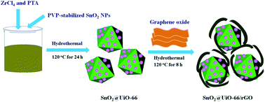
An effective ternary composite of SnO2@UiO-66/rGO was designed and synthesized. The as-prepared samples were characterized by various techniques, including powder X-ray diffraction (XRD), Raman spectroscopy, scanning electron microscopy (SEM), high resolution transmission electron microscopy (HRTEM), N2 adsorption–desorption isotherms, UV-vis diffuse reflection spectroscopy (DRS), zeta potential analysis, photoluminescence (PL) spectroscopy and electrochemical impedance spectroscopy (EIS). The photocatalytic activity of ternary SnO2@UiO-66/rGO, binary SnO2@UiO-66, SnO2@rGO, P25 TiO2 and SnO2 were studied by employing the degradation of rhodamine B (RhB) from water under visible light irradiation. The results showed that the degradation efficiency of SnO2@UiO-66/rGO was found to be 95.5% for RhB dyes within 150 min, which is much superior than the others. The enhanced photocatalytic property of the ternary composite can be attributed to the microporous structure, high surface area, enhanced visible light absorption, efficient charge transfer process, as well as the synergetic effect among SnO2 NPs, UiO-66 and rGO. Therefore, these kinds of MOF-based ternary composites have great potentiality in environmental remediation fields.


Introduction

Photocatalysis has attracted tremendous attention, because it offers a highly important route to solar-to-chemical energy conversion.1–4 The photocatalytic activity of catalysts with a nanostructure depends strongly on their composition and structure. In the past few decades, a series of traditional metal oxide semiconductors, such as TiO2, ZnO and SnO2, have been identified as active photocatalysts for photogradation of organic pollutants.5–9 Among them, SnO2 is a direct wide band gap semiconductor (Eg = 3.6 eV) with excellent photoelectronic properties, gas sensitivity, and superior chemical stability, which has already been regarded as a promising photocatalyst material.10,11 In particular, some reports have mentioned that SnO2 can be better than TiO2 and ZnO when used as an electronic acceptor. However, the main serious obstacles limiting its further practical applications include rapid recombination of photogenerated electron–hole pairs, low-light-harvesting efficiency and poor visible light response.12 In order to overcome the above problems, more efforts have been made.13–15 For example, Zhang et al. reported the binary Ag3PO4/SnO2 semiconductor nanocomposites improving the separation of photogenerated electron–hole pairs, thus enhancing the photocatalytic activity under the irradiation of visible light.16 Wang et al. also synthesized a kind three-dimensional SnO2/α-Fe2O3 semiconductor hierarchical composite, which exhibited excellent visible-light photocatalytic ability for the degradation of methylene blue due to the large specific surface area, wide visible-light absorption range, and efficient electron–hole pair separation properties of the SnO2/α-Fe2O3 nanoheterostructures.17 Nevertheless, it is still of great interest to search for improved activity and high efficiency SnO2-based photocatalysts.

Metal–organic frameworks (MOFs), consisting of organic linkers and metal-oxo clusters, have been emerging as a new class of crystalline porous materials and have attracted great interest in many prospective applications.18–20 Some MOFs like UiO-66-NH2 (the main composition: 2-aminoterephthalic acid and ZrCl4), MOF-5 (the main composition: zinc nitrate hexahydrate and 1,4-benzenedicarboxylic acid) and MIL-100(Fe) (the main composition: 1,3,5-benzenetricarboxylic acid and FeCl3·6H2O) are regarded as potential candidates for photocatalysis owing to semiconductor behavior.21–23 Recently, MOFs were also reported as popular host matric for dispersing semiconductor nanoparticles (NPs), which exhibited superior photocatalytic performance.24,25 The high surface area, caging effects and the pores of MOFs can well disperse the semiconductor NPs and limit the aggregation of nanopartciles. On the other hand, more active adsorption sites and photocatalytic reaction centers are present. Significantly, some researchers believe that the synergistic effect between MOFs and semiconductor could promote the charge separation, which is beneficial for photocatalysis. However, it suffers from a big disadvantage that the structure of MOFs is accessible to be destroyed after semiconductor NPs are introduced.

Recently, graphene (GN) has also been regarded as a kind of ideal functional material for photocatalyst carrier and promoter to accept and shuttle electrons photogenerated from semiconductors upon light irradiation, thus enhancing the photoactivity of semiconductors.26 For example, in the case of GN–TiO2 composites, Ma et al. described that graphene acted as an electron-acceptor material to effectively hinder the electron–hole pair recombination of TiO2.27 Unfortunately, the electron transfer and the recombination of photo-generated charge carriers still exist for those of GN–metal oxide semiconductors materials, decreasing their photocatalytic performance. In order to break the above bottlenecks, it is an effective approach by building ternary composite in which the wide band gap semiconductors are promising to realize efficient photocatalysis.28–32 In addition, such ternary composite shows integrative effect of increased surface area and more efficient separation of the photogenerated electron–hole pairs as well as the enhanced visible-light absorption intensity.

In this paper, in order to keep the structure of the MOF and improve the photocatalytic activity under visible light irradiation, a ternary composite is designed and synthesized, specifically referring to SnO2@UiO-66/rGO (which is generally called graphene). The schematic illustration is shown in Fig. 1. A two-step wet-chemical synthesis method has been developed to prepare SnO2@UiO-66/rGO hybrids. The photocatalytic performance and recyclability of SnO2@UiO-66/rGO hybrids were investigated in detail by employing the degradation of RhB under visible light. It was found that ternary composite showed a superior activity to that of SnO2@UiO-66, SnO2@rGO, P25 TiO2 and SnO2. To the best of our knowledge, this is the first report of the synthesis of SnO2@UiO-66/rGO ternary hybrids and the application in the field of photocatalysis, which may provide a new catalyst for visible light-induced photodegradation of organic contaminants.


image file: c6ra18140f-f1.tif
Fig. 1 Schematic illustration for the synthesis of SnO2@UiO-66/rGO composite.

Experimental section

Materials

All chemical reagents were of analytical grade and were used as received.

Preparation of SnO2@UiO-66 composite

The synthesis of PVP-stabilized SnO2 NPs suspension was adopted the method reported by Lu's group (see ESI).33 SnO2@UiO-66 composite was prepared via a simply solvothermal method. Typically, ZrCl4 (0.232 g, 1.0 mmol), terephthalic acid (0.166 g, 1.0 mmol) and acetic acid (3 mL) were dissolved in DMF (50 mL). Subsequently, 12 mL of the self-prepared PVP-stabilized SnO2 NPs suspension (0.25 mg mL−1) was added, and the mixture was ultrasonically treated for about 15 min. Finally, the solution was transferred to a 100 mL Teflon-lined stainless steel autoclave. The autoclave was sealed and heated in an oven at 120 °C for 24 h under autogenously pressure. After cooled naturally, the sample was purified with anhydrous methanol for several times.

Preparation of SnO2@UiO-66/rGO composite

GO was prepared from purified natural graphite according to a modified Hummers' method.34 The SnO2@UiO-66/rGO composite was synthesized by solvothermal treatment. In a typical experiment, 25 mg of GO and the as-prepared 50 mg of SnO2@UiO-66 were ultrasonically dispersed in 20 mL of EtOH/ethylene glycol (v/v = 9/1) for about 15 min. The resulting suspension was transferred into a Teflon-lined stainless steel autoclave. The autoclave was heated in an electric oven at 120 °C for 8 h, and then cooled to room temperature naturally. The product was collected by centrifugation and washed with alcohol three times.

Results and discussion

Material characterizations

The structural characterizations of SnO2, SnO2@UiO-66 and SnO2@UiO-66/rGO were performed. Fig. 2 plots the XRD patterns of the as-synthesized samples. Three broad characteristic peaks located at 26.7°, 33.7° and 51.6° can be indexed respectively to the (110), (101) and (211) phases of tetragonal rutile-type SnO2 (JCPDS no. 41-1445), which confirms the generation of SnO2 NPs. In the case of SnO2@UiO-66, the positions and relative intensities of the peaks for the UiO-66 frameworks is consistent with the previous reports, demonstrating that UiO-66 is successfully prepared.35 Similar to SnO2@UiO-66, SnO2@UiO-66/rGO composite exhibits excellent crystalline characteristic of SnO2 and UiO-66 respectively (Fig. 2c). After rGO was introduced, there is no obvious loss of crystallinity for the obtained SnO2@UiO-66/rGO, suggesting that the integrity of the UiO-66 framework is maintained. No peak is assigned to GO, indicating that it was reduced to rGO during the hydrothermal process.
image file: c6ra18140f-f2.tif
Fig. 2 XRD patterns of (a) SnO2, (b) SnO2@UiO-66 and (c) SnO2@UiO-66/rGO hybrid photocatalysts.

To further clarify the structural and electronic properties of the as-prepared samples, Raman analysis was performed. Fig. 3 shows the room-temperature Raman spectra of the as-synthesized SnO2, SnO2@UiO-66 and SnO2@UiO-66/rGO hybrid photocatalysts. The peak of SnO2 A1g phonon mode is detected at 625 cm−1, which is related to the expansion vibration mode of Sn–O bonds. The broadened strong band at 574 cm−1 is ascribed to crystal defects or defect levels associated with oxygen vacancies, which was in good agreement with the reported results for SnO2 nanocones.36 The two peaks can be observed clearly in the samples of SnO2 and SnO2@UiO-66. But no typical peaks assigned to SnO2 NPs are observed, which can be ascribed to the relatively low peak intensity of SnO2 phase as compared with the predominant peaks of rGO. Besides, the Raman spectra of SnO2@UiO-66 and SnO2@UiO-66/rGO exhibit many features in the range of 400–1700 cm−1, which provide further evidence for the existence of UiO-66.37 The Raman spectra of the GO and SnO2@UiO-66/rGO is compared in Fig. 3c and d. The two main feature peaks located at 1380 cm−1 (k-point phonons of A1g symmetry, D-band) and 1585 cm−1 (E2g phonons of C sp2 atoms, G-band) can be seen. The D band corresponds to defects in the graphene oxide, while the G band is related to the graphitic hexagon-pinch mode. The intensity ratios of D band to G band (ID/IG) of GO and SnO2@UiO-66/rGO are 0.84 and 0.98. This indicates the successful reduction of GO by hydrothermal treatment in SnO2@UiO-66/rGO, at the same time, more defects have been brought and the longrange order structure of rGO is destructed.38,39 Interestingly, the G band is red-shifted by 13 cm−1 for SnO2@UiO-66/rGO hybrids. It is due to the electronic interaction between SnO2@UiO-66 NPs and rGO nanosheets.40 As a result, Raman spectra characteristics from SnO2@UiO-66/rGO hybrids indicate the successful reduction of GO and the attachment of SnO2@UiO-66 on the rGO sheets.


image file: c6ra18140f-f3.tif
Fig. 3 Room-temperature Raman spectrum of the as-prepared (a) SnO2, (b) SnO2@UiO-66, (c) GO and (d) SnO2@UiO-66/rGO hybrid photocatalysts.

The microscopic morphology of the as-prepared samples was studied using FESEM and TEM. It can be seen from Fig. 4a and b that UiO-66 displays octahedral structure with a narrow size distribution in range of 300–500 nm. The UiO-66 is intimately enwrapped by rGO nanosheets under the pronounced electrostatic interactions due to the negatively charged GO and the positively charged UiO-66, and the SnO2 NPs were adsorbed onto UiO-66. As shown in Fig. 4c, the SnO2 NPs with average size of 4 nm are well dispersed on the surface of UiO-66 matrix without obvious aggregation. HRTEM samples were sonicated for 10 min prior to investigate. Thus, it is evident that the bonding between the SnO2 and UiO-66 is very strong. The UiO-66 can be served as an adsorbent for the immobilization of SnO2 NPs due to the large surface and pore structure. An intimate contact is formed between SnO2, UiO-66 and rGO, and this contact is helpful for the charge separation and transfer. As can be seen from the enlarged image in Fig. 4d, the lattice fringe is observed to be 3.52 Å, which is related to the (110) plane of SnO2.


image file: c6ra18140f-f4.tif
Fig. 4 (a) FESEM, (b and c) TEM and (d) HRTEM micrographs of the SnO2@UiO-66/rGO catalysts.

The porous property of the photocatalyst samples were measured by N2 adsorption method. Fig. 5, S1 and Table 1 show the adsorption–desorption isotherms and the full datas. The BET surface areas of bare SnO2, rGO and UiO-66 are found to be 34.2 m2 g−1, 88.65 m2 g−1 and 758.16 m2 g−1, respectively. SnO2@UiO-66/rGO hybrids exhibit an IV-type adsorption curve with steep increases in N2 adsorption at a low relative pressure (P/P0 < 0.46) and obvious hysteresis loops at the P/P0 ranges of 0.51–0.78, which is associated with the micro- and meso-pore. The specific surface area of SnO2@UiO-66/rGO is 437.2 m2 g−1, which is lower than that of UiO-66, but much higher than the values of SnO2 and rGO. The pore-size distributions was calculated using the Barrett–Joyner–Halenda method and the desorption branch of the nitrogen isotherm. The average pore diameter of SnO2@UiO-66/rGO hybrid is 3.72 nm, indicating the formation of mesoporous materials. The highly porous structure can introduce photosensitive SnO2 NPs inside the organic bridging ligand and facilitate the photocatalytic reactions. In order to investigate the surface charge of as-prepared samples, zeta potential measurements were carried out, as shown in Table 1. The pure SnO2 has a zeta potential of about 26.5 mV, which is in good agreement with the results reported in previous studies.41,42 Meanwhile, a negative zeta potential (−13.2 mV) can be observed for SnO2@UiO-66/rGO hybrids. The enhanced negative surface charge in SnO2@UiO-66/rGO hybrids might be originated from the electron donation from rGO, which can increase the electron densities of the hybrids surface. The high negative value of a zeta potential suggests that positively charged RhB dyes can be more easily adsorbed by SnO2@UiO-66/rGO through electrostatic interaction.


image file: c6ra18140f-f5.tif
Fig. 5 (a) N2 adsorption–desorption isotherms and (b) average pore diameters of SnO2 NPs, SnO2@rGO, SnO2@UiO-66 and SnO2@UiO-66/rGO hybrid photocatalysts.
Table 1 Special surface areas (SBET), average pore diameter and zeta potentials of the photocatalysts
Samples SBET (m2 g−1) Average pore diameter (nm) Zeta potentials (mV)
SnO2 34.2 5.92 26.5
SnO2@rGO 189.5 2.85 −6.87
SnO2@UiO-66 579.0 3.38 1.73
SnO2@UiO-66/rGO 437.2 3.72 −13.2


The optical absorption of as-synthesized SnO2@UiO-66/rGO composites was characterized by DRS in Fig. 6a, which compared to those of the individual components SnO2 NPs, UiO-66 and rGO. The band gap energy (Eg) of SnO2 and UiO-66 and SnO2@UiO-66/rGO can be estimated, respectively, according to the eqn (1) and the diagram is shown in Fig. 6b.

 
αhν = k(Eg)n/2 (1)
where k represents a constant, n is determined by the type of optical transition of a semiconductor, which depends on whether the transition is direct (n = 1) or indirect (n = 4).43,44 The UV-vis spectrum of UiO-66 displays ultraviolet light absorption behaviour with an absorption edge of 360 nm, corresponding to a 3.45 eV band gap. And the SnO2 NPs almost do not absorb any visible light due to the wide band gap of Eg = 3.6 eV. As for the SnO2@UiO-66/rGO composites, a notable absorption extension in the visible-light region can be observed, which is similar to that of rGO. The obvious red shift of absorption edge may come from the raising of base absorption line which is mainly contributed by the increase of graphene load. The band gaps of SnO2@UiO-66/rGO composites estimated from the intercept of the tangents to the plots were 3.3 eV, which further confirms the formation of a hybrid structure between SnO2@UiO-66 and rGO.


image file: c6ra18140f-f6.tif
Fig. 6 (a) UV-vis DRS spectra of SnO2, UiO-66, rGO and SnO2@UiO-66/rGO composites and (b) the band gaps of SnO2, UiO-66 and SnO2@UiO-66/rGO estimated from the intercept of the tangents to the plots.

Photogenerated electrons and holes are easily separated in the transfer process, improving quantum efficiency greatly. In order to investigate the effect of rGO modification on migration, transfer and recombination processes of photogenerated electron–hole pairs in composite samples, photoluminescence (PL) spectra have been performed. Fig. 7a presents the PL spectra of SnO2@UiO-66 and SnO2@UiO-66/rGO photocatalyst at room temperature. Upon photo-excitation at 305 nm, SnO2@UiO-66 photocatalyst exhibited a strong violet luminescence centered at 388 nm, which could be attributed to the band gap recombination of electron–hole pairs. Comparatively, the PL intensity of SnO2@UiO-66/rGO photocatalyst decreases significantly, suggesting much lower recombination rate of photo-generated electrons–hole (e–h+) pairs. The rGO and SnO2@UiO-66 can cooperatively improve the separation of light-trigged charge carries. For the SnO2@UiO-66/rGO hybrid, the direct electron transfer is energetically favorable from the conduction band of photoexcited rGO to SnO2@UiO-66, so that enhances the separation of photogenerated electrons and holes. To further clarify the advantage of SnO2@UiO-66/rGO over SnO2@UiO-66 in improving the separation efficiency of photoexcited electron–hole pairs, we have performed the electrochemical impedance spectra (EIS) Nyquist plot. As shown in Fig. 7b, SnO2@UiO-66/rGO exhibits depressed semicircles compared with SnO2@UiO-66, which manifests a decrease in the contact and charge transfer resistances by forming nanocomposite of SnO2@UiO-66 with rGO. Namely, the more efficient transfer of charge carriers was obtained over SnO2@UiO-66/rGO hybrids than SnO2@UiO-66.


image file: c6ra18140f-f7.tif
Fig. 7 (a) Room-temperature stable state photoluminescence spectra and (b) Nyquist impedance plots of SnO2@UiO-66 and SnO2@UiO-66/rGO photocatalyst.

Photocatalytic activity

The RhB photodegradation curves via the as-prepared SnO2@UiO-66/rGO hybrids were evaluated under visible-light irradiation (λ > 420 nm) (Fig. S2). For comparison, SnO2, P25 TiO2, SnO2@UiO-66 and SnO2@rGO were tested under the same conditions. All suspensions of catalyst and RhB dye achieve the adsorption–desorption equilibration after a 60 min dark adsorption process. Obviously, in the presence of SnO2@UiO-66/rGO catalysts, RhB dye degradation efficiency is found to be 95.5% within 150 min and the photocatalytic activity is superior to SnO2, P25 TiO2, SnO2@UiO-66 and SnO2@rGO. The increment of photocatalytic activity for SnO2@UiO-66/rGO may be ascribed to (i) the electrostatic attraction between the negatively charged SnO2@UiO-66/rGO and cationic dye RhB, (ii) the large specific surface area (437 m2 g−1) and the mesoporous structure of SnO2@UiO-66/rGO, (iii) and the special π-conjugation structure of rGO.

Fig. 8a shows the comparison of photocatalytic degradation curves of RhB in the presence of SnO2, P25 TiO2, SnO2@UiO-66, SnO2@rGO and SnO2@UiO-66/rGO catalysts. P25 TiO2 exhibits a higher photocatalytic activity than our synthesized SnO2 with single anatase phase. Considering that SnO2 and P25 TiO2 cannot absorb light with a wavelength greater than 420 nm, the observed photocatalytic activity may be due to the dye-sensitization effect since the colored RhB dye usually absorbs visible light.45 The SnO2@rGO composites display a significantly improved photodegradation efficiency to RhB compared with P25 TiO2 and SnO2, achieving a degradation percentage of more than 86% in 150 min. Among all the samples tested, the degradation efficiency of SnO2@UiO-66/rGO is found to be 95.5% for RhB dyes within 150 min, which is much superior than the others. The substantial photoactivity enhancement derives from the synergistic interaction between rGO acting as efficient electron transporter and collector in conjunction with two different semiconductors simultaneously. To quantitatively evaluate the reaction kinetics of RhB degradation catalyzed by these catalysts, the corresponding apparent reaction rate constants (k) were calculated using the pseudo-first-order kinetic model (ln(C0/C) = kt), as shown in Fig. 8b.46,47 The order of RhB degradation rate for asprepared photocatalysts is SnO2@UiO-66/rGO (0.0251 min−1) > SnO2@rGO (0.0146 min−1) > SnO2@UiO-66 (0.0137 min−1) > P25 TiO2 (0.0052 min−1) > SnO2 (0.0043 min−1).


image file: c6ra18140f-f8.tif
Fig. 8 (a) Photocatalytic degradation curves and (b) the apparent reaction rate constants (k) of the RhB using different photocatalysts after 150 min of visible light irradiation: SnO2 NPs, P25 TiO2, SnO2@UiO-66, SnO2@rGO and SnO2@UiO-66/rGO.

Photocatalytic mechanism of SnO2@UiO-66/rGO catalyst

It has been widely investigated that the photodegradation of RhB were strongly depended on the active oxidants in the reaction system. In order to evaluate the role of these active oxidants, scavengers were added to the photocatalytic system. These were isopropyl alcohol for ˙OH, EDTA-2Na for the holes, and p-benzoquinone for ˙O2−.48,49 As shown in Fig. 9, there are no noticeable change in RhB concentration after 1 h stirring under visible light irradiation but without a photocatalyst. The photodegradation of RhB is slightly inhibited by the addition of isopropyl alcohol or EDTA-2Na, while it is much suppressed when p-benzoquinone is included. This indicates that the dye degradation is mainly driven by the participation of the ˙O2−, and to a lesser extent by the contribution of ˙OH and h+ radicals in this photocatalytic system.
image file: c6ra18140f-f9.tif
Fig. 9 Effect of different scavengers on the photodegradation of RhB by SnO2@UiO-66/rGO hybrids under visible-light irradiation.

After the RhB adsorption–desorption equilibrium in dark, an adsorption quantity of 75.8 mg RhB per g photocatalyst is obtained due to the large surface area, porous structure and the π–π conjugation between the RhB molecules and the rGO surface. More importantly, during the photodegradation of RhB under visible light, dye photosensitization plays the key role with pure SnO2 as photocatalyst: RhB (+0.95 V vs. NHE) is excited to RhB* (−1.42 V vs. NHE) when irradiated by visible light, then the electrons are injected from RhB* into the conduction band of SnO2 (−0.5 V vs. NHE),50 which induces the formation of oxidized species that are essential for photodegradation. As a result, the RhB adsorbed onto SnO2@UiO-66/rGO photocatalyst can be excited to RhB* under visible light irradiation, followed by an electron transfer from the RhB* to SnO2 NPs or UiO-66 or rGO. The RhB˙+ is finally degraded by the reactive oxygen species or holes. However, only small amount of the dye is oxidized by photogenerated holes and ˙OH radical, most of the dye is directly destroyed by the O2˙. Based on the above analysis, a possible proposed mechanism for the production of reactive oxygen species over SnO2@UiO-66/rGO composite under visible light irradiation can be summarized by the following reactions:

 
image file: c6ra18140f-t1.tif(2)
 
RhB + → RhB* → RhB˙+ + e (3)
 
SnO2@UiO-66/rGO + → SnO2@UiO-66/rGO (h+ + e) (4)
 
e + O2 → O2˙ (5)
 
RhB/RhB˙+ + O2˙/˙OH → degradation products (6)
 
RhB/RhB˙+ + h+ → degradation products (7)

To comprehend the excellent photocatalytic activity of the SnO2@UiO-66/rGO composite, one has to take into accounts several factors (e.g. adsorption ability, band structure, separation performance of the photo-generated electrons and holes, and specific surface area) that might contribute to the photocatalytic performance. Notably, non-uniform porous structures are beneficial for the RhB adsorption onto the surface of SnO2@UiO-66. The large specific surface area (Table 1, 437 m2 g−1) of SnO2@UiO-66/rGO can offer more active adsorption sites and photocatalytic reaction centers, which could result in an enhanced photocatalytic activity. More O2 in water acting as the electron scavenger could be reduced by e to produce O2˙, which is an important active oxidative specie in the degradation of RhB. Owing to the presence of rGO sheets, the photogenerated electrons are captured by the rGO. Firstly, rGO here benefits direct on the surface of SnO2@UiO-66 and improves the light absorption region of the composite. Secondly, the unique 2D structure of rGO sheets allow the photocatalytic reactions to take place both on the surface of UiO-66 and rGO sheets, which increases the reaction centers and offers more catalytic sites. Thirdly, the hybridization of rGO sheets with semiconductor nanostructures can facilitate charge migration and reduce the recombination of electron–hole pairs of the rGO based photocatalysts, which is well complied in the literatures.51,52 On the one hand, the two-dimensional planar conjugation structure in rGO facilitates interfacial charge transfer along the rGO sheets to any electron acceptors like O2. Thus, the charge recombination could be effectively suppressed in the composite. The inhibition of recombination for electron–hole pairs results in forming more reactive species such as O2˙ and hydroxyl radicals (˙OH), which could promote the degradation of RhB.

Recyclability of SnO2@UiO-66/rGO catalysts

To evaluate the reusability of the SnO2@UiO-66/rGO photocatalyst, we performed five cycles experiments of photocatalytic processes toward RhB dye using the recycled SnO2@UiO-66/rGO. After each photocatalytic experiment, the photocatalyst was separated from the solution by centrifuging, washed with deionized water and dried. As shown in Fig. 10, no obvious changes in photocatalytic efficiency indicate the SnO2@UiO-66/rGO can keep stable recyclability. The efficiency for the photodegradation of RhB after 5th-runs is still kept above 91.2%, indicating that the SnO2@UiO-66/rGO can be used successively without the variation of photocatalytic performance during the oxidation of pollutant. These results demonstrate unambiguously that the SnO2@UiO-66/rGO hybrid is a stable, efficient, and recyclable pollutant photocatalyst.
image file: c6ra18140f-f10.tif
Fig. 10 Recyclability of SnO2@UiO-66/rGO photocatalyst in five successive cycles for RhB dye degradation over visible-light system.

Conclusions

In summary, a novel ternary SnO2@UiO-66/rGO hybrid photocatalyst with large surface area, high activity and stability was successfully fabricated via a facile two-step hydrothermal method. SnO2 NPs were well-dispersed on the UiO-66 matrix, and then SnO2@UiO-66 hybrids were intimately enwrapped by rGO nanosheets based on electrostatic attractive interactions. Under visible light irradiation, the as-prepared SnO2@UiO-66/rGO photocatalyst exhibited a remarkably higher photocatalytic performance for the degradation of RhB. The improved photocatalytic performance was ascribed to the results of adsorption as well as the photodegradation mechanisms. This three-component SnO2@UiO-66/rGO heterostructure combining the two-dimensional planar conjugation structure and high electrical conductivity of rGO, the large surface area and porous structure of UiO-66, and the synergistic effect among SnO2 NPs, UiO-66 and rGO into a single structure may provide a new option to design highly efficient SnO2-based photocatalysts.

Acknowledgements

This work was supported by Priority Academic Program Development of Jiangsu Higher Education Institutions (1281220030), China Postdoctoral Science Foundation funded project (2016M591779) and Natural Science Foundation of Jiangsu Province (BK20140547).

References

  1. D. Ravelli, D. Dondi, M. Fagnoni and A. Albini, Chem. Soc. Rev., 2009, 38, 1999 RSC.
  2. N. Vallavoju and J. Sivaguru, Chem. Soc. Rev., 2014, 43, 4084 RSC.
  3. X. Li, J. G. Yu and M. Jaroniec, Chem. Soc. Rev., 2016, 45, 2603 RSC.
  4. R. Asahi, T. Morikawa, H. Irie and T. Ohwaki, Chem. Rev., 2014, 114, 9824 CrossRef CAS PubMed.
  5. H. Park, H. I. Kim, G. H. Moon and W. Choi, Energy Environ. Sci., 2016, 9, 411 CAS.
  6. M. Z. Ge, C. Y. Cao, J. Y. Huang, S. H. Li, Z. Chen, K. Q. Zhang, S. S. Al-Deyab and Y. K. Lai, J. Mater. Chem. A, 2016, 4, 6772 CAS.
  7. P. Li, Y. Lan, Q. Zhang, Z. Zhao, T. Pullerits, K. Zheng and Y. Zhou, J. Phys. Chem. C, 2016, 120, 9253 CAS.
  8. S. D. Zhuang, X. Y. Xu, B. Feng, J. Hu, Y. Pang, G. Zhou, L. Tong and Y. X. Zhou, ACS Appl. Mater. Interfaces, 2014, 6, 613 CAS.
  9. S. Kumar, A. Baruah, S. Tonda, B. Kumar, V. Shanker and B. Sreedhar, Nanoscale, 2014, 6, 4830 RSC.
  10. S. S. Wu, H. Q. Cao, S. F. Yin, X. W. Liu and X. R. Zhang, J. Phys. Chem. C, 2009, 113, 17893 CAS.
  11. X. Chen, B. H. Zhou, S. L. Yang, H. S. Wu, Y. Wu, L. Wu, J. Pan and X. Xiong, RSC Adv., 2015, 5, 68953 RSC.
  12. M. T. Uddin, Y. Nicolas, C. Olivier, T. Toupance, L. Servant, M. M. Muller, H. J. Kleebe, J. Ziegler and W. Jaegermann, Inorg. Chem., 2012, 51, 7764 CrossRef CAS PubMed.
  13. K. Sridharan and T. J. Park, Appl. Catal., B, 2013, 134–135, 174 CrossRef CAS.
  14. K. Sridharan, E. Jang and T. J. Park, CrystEngComm, 2013, 15, 8241 RSC.
  15. Y. C. Zhang, Z. N. Du, K. W. Li, M. Zhang and D. D. Dionysiou, ACS Appl. Mater. Interfaces, 2011, 3, 1528 CAS.
  16. L. L. Zhang, H. C. Zhang, H. Huang, Y. Liu and Z. H. Kang, New J. Chem., 2012, 36, 1541 RSC.
  17. S. W. Zhang, J. X. Li, H. H. Niu, W. Q. Xu, J. Z. Xu, W. P. Hu and X. K. Wang, ChemPlusChem, 2013, 78, 192 CrossRef CAS.
  18. S. Horike, S. Shimomura and S. Kitagawa, Nat. Chem., 2009, 1, 695 CrossRef CAS PubMed.
  19. L. Y. Chen, X. D. Chen, H. L. Liu and Y. W. Li, Small, 2015, 11, 2642 CrossRef CAS PubMed.
  20. Q. H. Yang, Q. Xu, S. H. Yu and H. L. Jiang, Angew. Chem., Int. Ed., 2016, 55, 3685 CrossRef CAS PubMed.
  21. L. Shi, T. Wang, H. B. Zhang, K. Chang and J. Ye, Adv. Funct. Mater., 2015, 25, 5360 CrossRef CAS.
  22. J. Xu, S. He, H. Zhang, J. Huang, H. Lin, X. Wang and J. L. Long, J. Mater. Chem. A, 2015, 3, 24261 CAS.
  23. H. Wang, X. Yuan, Y. Wu, G. Zeng, X. Chen, L. Leng and H. Li, Appl. Catal., B, 2015, 174–175, 445 CrossRef CAS.
  24. Y. J. Wang, Y. Zhang, Z. Jiang, G. Jiang, Z. Zhao, Q. Wu, Y. Liu, Q. Xu, A. Duan and C. M. Xu, Appl. Catal., B, 2016, 185, 307 CrossRef CAS.
  25. X. Y. Li, Y. H. Pi, Q. B. Xia, Z. Li and J. Xiao, Appl. Catal., B, 2016, 191, 192–201 CrossRef CAS.
  26. C. H. Zhang, L. H. Ai and J. Jiang, Ind. Eng. Chem. Res., 2015, 54, 153 CrossRef CAS.
  27. Y. Ma, F. L. Formal, A. Kafizas, S. R. Pendlebury and J. R. Durrant, J. Mater. Chem. A, 2015, 3, 20649 CAS.
  28. C. Zeng, Y. M. Hu, Y. X. Guo, T. Zhang, F. Dong, Y. Zhang and H. W. Huang, ACS Sustainable Chem. Eng., 2016, 4, 3305 CrossRef CAS.
  29. M. Selim Arif Sher Shah, K. Zhang, A. Reum Park, K. S. Kim, N. G. Park, J. H. Park and P. J. Yoo, Nanoscale, 2013, 5, 5093 RSC.
  30. B. C. Qiu, Y. X. Deng, Q. Y. Li, B. Shen, M. Xing and J. L. Zhang, J. Phys. Chem. C, 2016, 120, 12125 CAS.
  31. W. K. Jo and N. C. S. Selvam, Dalton Trans., 2015, 44, 16024 RSC.
  32. Y. J. Wu, D. M. Chu, P. Yang, Y. K. Du and C. Lu, Catal. Sci. Technol., 2015, 5, 3375 CAS.
  33. G. Lu, S. Z. Li, Z. Guo, O. K. Farha, B. G. Hauser, X. Qi, Y. Wang, X. Wang, S. Han, X. Liu, J. S. Duchene, H. Zhang, Q. Zhang, X. Chen, J. Ma, S. C. J. Loo, W. D. Wei, Y. Yang, J. T. Hupp and F. W. Huo, Nat. Chem., 2012, 4, 310 CrossRef CAS PubMed.
  34. W. S. Hummers and R. E. Offeman, J. Am. Chem. Soc., 1958, 80, 1339 CrossRef CAS.
  35. L. J. Shen, M. B. Luo, Y. Liu, R. W. Liang, F. F. Jing and L. Wu, Appl. Catal., B, 2015, 166–167, 445 CrossRef CAS.
  36. G. Cheng, J. M. Wang, X. W. Liu and K. X. Huang, J. Phys. Chem. B, 2006, 110, 16208 CrossRef CAS PubMed.
  37. Z. W. Jiang, P. F. Gao, L. Yang, C. Z. Huang and Y. F. Li, Anal. Chem., 2015, 87, 12177 CrossRef CAS PubMed.
  38. Z. Y. Wang, Y. Zhang, S. Liu and T. Zhang, Sens. Actuators, B, 2016, 222, 893 CrossRef CAS.
  39. J. H. Huo, J. H. Wu, M. Zheng, Y. Tu and Z. Lan, J. Power Sources, 2015, 293, 570 CrossRef CAS.
  40. B. Das, R. Voggu, C. S. Rout and C. N. R. Rao, Chem. Commun., 2008, 41, 5155 RSC.
  41. S. S. Wu, S. Yuan, L. Y. Shi, Y. Zhao and J. H. Fang, J. Colloid Interface Sci., 2010, 346, 12 CrossRef CAS PubMed.
  42. N. Srivastava and M. Mukhopadhyay, Ind. Eng. Chem. Res., 2014, 53, 13971 CrossRef CAS.
  43. A. Wang, Y. J. Zhou, Z. L. Wang, M. Chen, L. Y. Sun and X. Liu, RSC Adv., 2016, 6, 3671 RSC.
  44. Y. P. Zang, L. P. Li, X. G. Li, R. Lin and G. S. Li, Chem. Eng. J., 2014, 246, 277 CrossRef CAS.
  45. H. Wang, X. Yuan, Y. Wu, G. Zeng, X. Chen, L. Leng and H. Li, Appl. Catal., B, 2015, 174–175, 445 CrossRef CAS.
  46. M. R. Hoffmann, S. T. Martin, W. Choi and D. W. Bahnemann, Chem. Rev., 1995, 95, 69 CrossRef CAS.
  47. X. M. Zhou, J. Y. Lan, G. Liu, K. Deng, Y. L. Yang, G. J. Nie, J. G. Yu and L. J. Zhi, Angew. Chem., Int. Ed., 2012, 51, 178 CrossRef CAS PubMed.
  48. L. Mohapatra, K. Parida and M. Satpathy, J. Phys. Chem. C, 2012, 116, 13063 CAS.
  49. L. G. Devi and R. Kavitha, Appl. Catal., B, 2013, 140–141, 559–587 CrossRef CAS.
  50. L. Pan, J. J. Zou, S. B. Wang, Z. F. Huang, X. W. Zhang and L. Wang, Appl. Surf. Sci., 2013, 268, 252–258 CrossRef CAS.
  51. N. Zhang, M. Q. Yang, S. Q. Liu, Y. G Sun and Y. J. Xu, Chem. Rev., 2015, 115, 10307 CrossRef CAS PubMed.
  52. L. Z. Huang and B. S. Liu, RSC Adv., 2016, 6, 17873 RSC.

Footnote

Electronic supplementary information (ESI) available. See DOI: 10.1039/c6ra18140f

This journal is © The Royal Society of Chemistry 2016
Click here to see how this site uses Cookies. View our privacy policy here.