
Carbide decorated carbon nanotube electrocatalyst for high-efficiency hydrogen evolution from seawater†
Yuanyuan Zhaoa,
Qunwei Tang*a,
Benlin Hea and
Peizhi Yangb
aInstitute of Materials Science and Engineering, Ocean University of China, Qingdao 266100, China. E-mail: tangqunwei@ouc.edu.cn; Fax: +86-532-66782533; Tel: +86-532-66782533
bKey Laboratory of Advanced Technique & Preparation for Renewable Energy Materials, Ministry of Education, Yunnan Normal University, Kunming 650500, China
First published on 26th September 2016
Abstract
Pursuit of robust electrocatalysts has been a persistent objective for hydrogen evolution from seawater. We present here an experimental realization of an efficient Co3Mo3C decorated carbon nanotube (Co3Mo3C/CNT) electrocatalyst with exceptionally high electrocatalytic activity and good durability through a simple thermal decomposition method for hydrogen evolution reaction (HER), yielding an onset overpotential as low as 42 mV and an exchange current density up to 0.415 mA cm−2 in seawater. Notably, the resultant Co3Mo3C/CNT electrocatalyst displays a promising stability when suffering persistent operation over 26 h in seawater. In comparison with pristine Ni foam electrode, the Co3Mo3C/CNT can markedly reduce the overpotential for hydrogen evolution and therefore enhance HER kinetics.
1. Introduction
Hydrogen energy is a renewable and abundant resource to reduce our dependence on fossil fuels and reduce greenhouse gas emission,1,2 and water splitting is believed to be a simple method for hydrogen evolution.3–5 Since the creative detection on water splitting by TiO2 electrode,6 it has been more than forty years, however, there are still some technical challenges in both the hydrogen evolution reaction (HER) and the oxygen evolution reaction (OER).7–13 Pt-group metals are currently the preferred electrocatalysts for HER, but the high cost of these noble metal are gigantic burden for their commercial application.14–17 By addressing this issue, many focuses have been placed on creating Pt-like candidates such as transition metal carbides (TMCs) without sacrificing catalytic activity.18–21 TMCs are an important class of compounds with remarkable catalytic activities,22–26 and notably Co3Mo3C is active for catalyzing the hydrodesulfurization (HDS) reaction.27–29 Since HDS and HER both rely on the reversible binding of the catalyst and hydrogen,30,31 it is expected that Co3Mo3C may also be active for the HER in water splitting. Apart from electrocatalytic activity, the long-term stability is still crucial for the practical utilization. Unfortunately, most of the electrocatalysts are commonly active in acidic or alkaline solutions,32–34 which not only needs to add sodium hydroxide or sulfuric acid into water system for increasing electrical conductivity, but also leads to great challenges in developing anticorrosion-resistant electrodes. One of the solutions to this impasse is to develop seawater-stable and non-noble-metal HER catalysts and to directly realize hydrogen evolution from seawater.Since the pioneering creation of Co3Mo3C by Newsam,35 Bussell has followed the concept for bulk and alumina supported Co3Mo3C by a temperature-programmed nitridation and subsequent carburization route.36 Afterwards, Co–Mo carbide was prepared by Liang through a carbothermal hydrogen reduction method with activated carbon material as carbon source and support.37 Recently, Co3Mo3C and MCM41-supported Co3Mo3C catalyst have also been successfully prepared by Wang through a simple thermal decomposition method, showing an efficient activity in both reactions of HDS and hydrodenitrogenation (HDN).29 Due to the similar reaction mechanisms for HDS and HER, we present here the preparation of the Co3Mo3C/CNT electrocatalyst by a simple hexamethylenetetramine-based one-step thermal decomposition method and study on salient HER performance. Hexamethylenetetramine (HMT) has been used as a reduction agent and molybdate ion ligand, which is an organic compound containing both carbon and nitrogen elements.38,39 Compared to the synthesis of bimetallic nitride, a higher HMT dosage in the precursor is required synthesize bimetallic carbide. In other words, there is a phase transformation from nitride to carbide in the carbon-enriched pyrolysate produced from decomposition of excess HMT in the precursor.29 Meanwhile, the existence of the Co elements facilitate the formation of the carbon nanotubes. We finally get an efficient Co3Mo3C decorated CNT electrocatalyst with exceptionally high electrocatalytic activity and good durability through a simple one-step thermal decomposition method for hydrogen evolution reaction. The wormlike and porous microstructure of the Co3Mo3C/CNT electrocatalyst increases the specific surface area for HER. The closely interconnected structure is beneficial of shortening the electron transfer pathway and enabling rapid diffusion of ions and electrons, allowing for an enhanced electrocatalytic activity and good durability. When suffered HER in pristine seawater, the Co3Mo3C/CNT electrocatalyst is highly active with an onset overpotential of 42 mV, a Tafel slope of 0.249 V dec−1, and an exchange current density of 415 mA cm−2. The Co3Mo3C/CNT electrocatalyst maintains its activity for at least 26 h and needs overpotentials (η) of 124 and 782 mV to attain current densities of 10 and 200 mA cm−2, respectively.
2. Experimental
2.1. Materials
All chemicals were used as received without any further purification unless noted. Nickel foam (>99.5%, 1.5 mm) was purchased from Taiyuan Yingze Lizhiyuan Battery. Nafion (5 wt%) was purchased from Sigma-Aldrich. Pt/C (20 wt% Pt) was purchased from Johnson Matthey. The CNT we used was multi-walled carbon nanotube purchased from Shenzhen Nano-port Co., Ltd. with more than 5 μm in length and 7–15 nm in diameter. The target seawater was taken from Yellow Sea (China) and filtrated to remove organic and suspended species.2.2. Preparation of the working electrode
A precursor was prepared by dissolving (NH4)6Mo7O24·4H2O, Co(CH3COO)2·4H2O, and HMT with a mole ratio of 1![[thin space (1/6-em)]](https://www.rsc.org/images/entities/char_2009.gif) :7:37 in 15% NH3·H2O solution under agitation. The mixture was evaporated at room temperature under stirring for approximate 7 days to form a homogeneous slurry. Subsequently, the abovementioned slurry was dried under vacuum at 333 K over night and ground to obtain the powder precursor, which was then placed in a porcelain boat under a flow of argon (99.99%) and heated to 1023 K at a heating rate of 5 K min−1. After reaction at 1023 K for 2 h, the as-synthesized Co3Mo3C/CNT powders were cooled naturally under argon.
:7:37 in 15% NH3·H2O solution under agitation. The mixture was evaporated at room temperature under stirring for approximate 7 days to form a homogeneous slurry. Subsequently, the abovementioned slurry was dried under vacuum at 333 K over night and ground to obtain the powder precursor, which was then placed in a porcelain boat under a flow of argon (99.99%) and heated to 1023 K at a heating rate of 5 K min−1. After reaction at 1023 K for 2 h, the as-synthesized Co3Mo3C/CNT powders were cooled naturally under argon.
Ni foam was thoroughly rinsed by ultrasonic dispersing in acetone, deionized water, and hydrochloric acid for 30 min, respectively, followed by being rinsed with deionized water and dried in the air. Catalyst ink was prepared by dispersing 5 mg of the Co3Mo3C/CNT electrocatalyst into a solvent containing 990 μL of isopropanol and 10 μL of 5 wt% Nafion solution. The mixture was then ultrasonicated for 30 min to generate a homogeneous ink. The working electrodes was prepared by soaking a piece of Ni foam in the catalyst ink for about ten seconds and then dried under vacuum at 333 K for 12 h. The electrocatalyst loading amount was controlled at 0.89 mg cm−2. The preparation procedures of CNT or Pt/C modified Ni foam as well as loading amount were identical to that for Co3Mo3C/CNT modified Ni foam.
2.3. Electrochemical characterizations
All the electrochemical measurements were conducted on a CHI660E electrochemical workstation in a typical three-electrode setup, comprising an Ag/AgCl reference electrode, a counter electrode (CE) composed of a Pt sheet, and a working electrode, with an electrolyte solution of seawater. The schematic diagram of the device and the working electrode is shown in Scheme 1. Linear sweep voltammetry (LSV) was carried out in seawater with a scan rate of 1 mV s−1. If not specially instructed, the first cycle LSV curves were utilized to compare the catalytic performances. Onset overpotentials were determined according to the beginning of the linear regime in the Tafel plot. Electrochemical impedance spectroscopy (EIS) measurements were also conducted in the frequency range of 106 Hz to 10−2 Hz. The time dependency of catalytic currents during electrolysis for the catalyst was tested in seawater at η = 170 mV. In all measurements, the Ag/AgCl reference electrode was calibrated with respect to reversible hydrogen electrode (RHE). RHE calibration was performed experimentally according to reported method.40 In seawater, ERHE = EAg/AgCl + 0.197 V + 0.059 pH, and the pH of the seawater was 6.44. In the current work, Pt sheet could be stable under persistent operation as a counter electrode because the dissolution of Pt sheet initiated at 0.95 V (vs. RHE) in 0.1 M HClO4 at 23 °C.41,42 It was well known that Pt dissolution processes may be accelerated in an increasing pH aqueous solution during persistent operation. However, neutral seawater instead of acidic solution was employed as a target electrolyte for HER, therefore the dissolution reactions of Pt can be markedly restricted. | ||
| Scheme 1 Schematic diagram of the water-splitting device as well as microstructure of working electrode. | ||
2.4. Characterizations
The scanning electron microscopy (SEM) and transmission electron microscopy (TEM) images were obtained on SU8020 and Tecnai G2 F20 FEI instruments, respectively. X-ray diffraction (XRD) data were obtained on Bruker D8 Advance with CuKα radiation (λ = 1.5418 Å). Energy dispersive spectroscopy (EDS) measurements were performed on QUANTA250FEG. The BET surface area, pore volume, and pore size were measured on a micromeritics instrument 3Flex at liquid N2 temperature.3. Results and discussion
SEM in Fig. 1a and b images shows a homogeneously interpenetrated morphology by wormlike carbon nanotubes with 1–2 μm in length and around 100 nm in diameter, leaving loose feature for diffusion and increase active surface area, and Co3Mo3C grafted to these carbon nanotubes. The TEM characterize is utilized to cross-check the distinctive microstructure, as shown in Fig. 1c and d. The d-spacing values of 0.213 nm corresponds to the (511) crystallographic planes for Co3Mo3C, which proves the small particles are Co3Mo3C. The determination of d-spacing value at 0.339 nm suggests the presence of CNT (Fig. 1e). Meanwhile, the element mappings for C, Co and Mo give a credible evidence for the presence of Co3Mo3C on CNTs (Fig. 1f). The characteristic peaks centered at 2θ = 26.7°, 35.3°, 42.4°, 46.4°, 48.6°, 52.2°, 69.4°, 72.4°, and 74.7° correspond to the (311), (331), (511), (440), (531), (620), (733), (822), and (662) facets of Co3Mo3C (JCPDS no. 80-0339), respectively. The other characteristic peaks correspond to the facets of C (JCPDS no. 05-0625) (Fig. 1g). The Co3Mo3C/CNT electrocatalyst was submitted to thermogravimetric analysis (TGA) (Fig. 1h). The stable line below 369 °C suggested that there are no thermal decomposition reactions for Co3Mo3C/CNT electrocatalyst, while an increased weight peak at 369–508 °C was attributed to oxidation reactions of Co and Mo species. The increased weight arises from oxygen species in corresponding metal oxides. The abrupt weight reduction in temperature range of 508–647 °C allows for combustion of CNTs. After calculation, the Co3Mo3C loading on corresponding Co3Mo3C/CNT electrocatalyst is around 73.4 wt%. The nitrogen adsorption/desorption isotherm plot shows a BET specific surface area (SSA) of 30.8 m2 g−1 for the Co3Mo3C/CNT electrocatalyst (Fig. 1i), while the average pore diameter is about 3.8 nm which has been determined by BJH pore-size distribution curve (Fig. 1j). The large SSA can expose more catalytic sites for hydrogen adsorption. However, the porous microstructure provides channels for charge transportation and therefore increased HER kinetics. | ||
| Fig. 1 (a and b) SEM and (c and d) TEM images, (e) HRTEM image, and (f) element mapping of corresponding Co3Mo3C/CNT catalysts. (g) X-ray diffraction (XRD) profile, (h) thermogravimetric analysis (TGA) weight lost curve, (i) nitrogen adsorption/desorption isotherm plot, and (j) pore radius distribution curve of the Co3Mo3C/CNT electrocatalyst. | ||
The XPS spectra for the Co3Mo3C/CNT electrocatalyst are shown in Fig. 2. Carbon is the main ingredient (Fig. 2a). As shown in Fig. 2b, the dominant peak (64.73%) in the Co 2p3/2 XPS spectrum at 781.43 eV indicates the presence of Co2+,43,44 and the peak at 793.5 eV is assigned to Co 2p1/2.45 The weak peak located at 786.23 eV and 802.14 eV are attributed to satellite peaks.46 The main peaks of Mo 3d appear at 228.81 eV, 232.42 eV, and 235.66 eV, coming from the Mo4+ 3d5/2, Mo4+ 3d3/2, and Mo6+ species. The peaks at 228.81 (Mo4+ 3d5/2) and 232.42 eV (Mo4+ 3d3/2) confirm that the molybdenum is basically in its Mo(IV) state (Fig. 2c).47–50 In order to study the formation mechanism of Co3Mo3C/CNT catalysts, Wang has carefully tuned HMT dosages during synthesis processes.29 Their results demonstrate that low HMT dosage in the precursor results in bimetallic nitride, while high HMT dosage is beneficial to bimetallic carbide such as Co3Mo3C. Therefore, excessive HMT is crucial in realizing phase transformation from bimetallic nitride to bimetallic carbide.
 | ||
| Fig. 2 XPS spectra of the Co3Mo3C/CNT electrocatalyst: (a) survey spectrum, (b) Co 2p, (c) Mo 3d. | ||
The polarization curve of Co3Mo3C/CNT modified Ni foam electrode in seawater with a scan rate of 1 mV s−1 is shown in Fig. 3a. Pristine Ni foam, CNT modified Ni foam and Pt/C modified Ni foam were also studied for comparison. Due to the effects from ohmic resistance, the as-measured currents cannot demonstrate the intrinsic charge-transfer behaviors of electrocatalysts. To address this issue, an iR compensation has been applied to all electrochemical characterizations. Pristine Ni foam and CNT modified Ni foam show very poor HER activity. In sharp contrast, the Co3Mo3C/CNT modified Ni foam electrode is highly active toward the HER with an onset overpotential of 42 mV (vs. RHE) and it can get a current density as high as 200 mA cm−2 at an overpotential of 782 mV. The cathodic current density has an increasing evolution at more negative potentials, requiring overpotentials as low as 124, 577, and 782 mV to afford current densities of 10, 100, and 200 mA cm−2, respectively. There are not apparent deviations for other electrochemical parameters. By comparing the overpotential of 695 mV for pristine Ni foam to yield a current density of 10 mA cm−2, the markedly reduced overpotential for Co3Mo3C/CNT electrocatalyst demonstrates it to be promising for HER from seawater splitting.
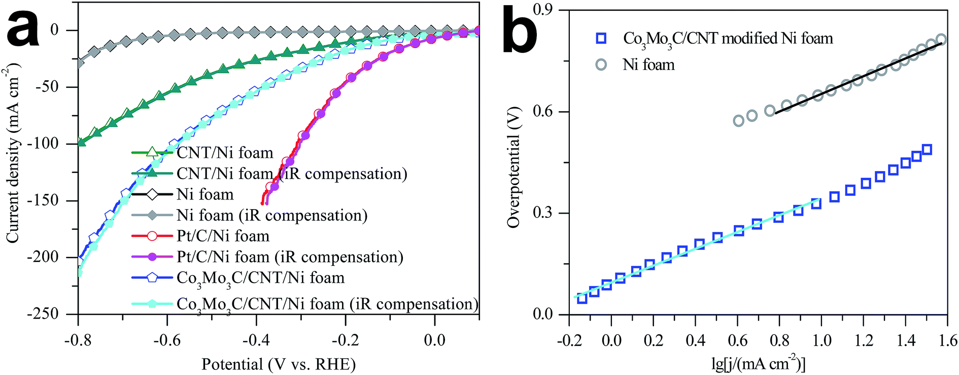 | ||
| Fig. 3 (a) Polarization curves of Ni foam, CNT modified Ni foam, Pt/C modified Ni foam and Co3Mo3C/CNT modified Ni foam electrode. (b) The corresponding Tafel plots recorded at a scan rate of 1 mV s−1. | ||
The Tafel plots of Ni foam and Co3Mo3C/CNT modified Ni foam electrode in seawater determined at a scan rate of 1 mV s−1 are shown in Fig. 3b. The linear portions of the Tafel plots are fitted by Tafel equation (η = blogj + a, where η is the overpotential, b refers to Tafel slope, j is the current density, and a is the intercept interrelate with the exchange current density j0). The Tafel slopes of Ni foam and Co3Mo3C/CNT modified Ni foam electrode are calculated to be 0.262 and 0.249 V dec−1, respectively. The exchange current density (j0) of the Co3Mo3C/CNT modified Ni foam electrode is approximately 0.415 mA cm−2, which is 13 times larger than that of Ni foam electrode and much higher than those from other HER catalysts.43,51–55 The higher j0 and the more positive onset potential for the Co3Mo3C/CNT modified Ni foam electrode are possibly a result of the HER occurring on a porous matrix with higher SSA and the high catalytic activity of Co3Mo3C/CNT.56,57
Electrochemical impedance spectroscopy (EIS) is investigated at various HER overpotentials to demonstrate the relative enhancement of the catalytic activity. As shown in Fig. 4 the Nyquist and Bode EIS plots (Fig. 4b and c), the plot for the Co3Mo3C/CNT modified Ni foam electrode has two semicircles at all overpotentials, indicating two electrochemical reaction processes for realizing HER in seawater. The first one at high frequency correlates with the large surface of the electrode, whereas the other at low frequency region is related to the kinetics of the HER process. From the low-frequency charge-transfer resistance (Rct) as a function of overpotentials presented in Fig. 4d, one can find that the Rct decreases from 15.8 ohm cm2 at 42 mV to 0.1 ohm cm2 at 700 mV, allowing for accelerated HER process at increasing overpotentials. This conclusion can be supported by the electron lifetime (τ = 1/2πf, f is the frequency at maximum peak), and the electron lifetime of the carbon nanotube supported Co3Mo3C electrocatalyst and at various HER overpotential was shown in Table 1.
 | ||
| Fig. 4 (a) Nyquist and (b and c) Bode EIS plots of the Co3Mo3C/CNT modified Ni foam electrode at various HER overpotentials in seawater. (d) The low-frequency charge transfer resistance Rct and equivalent electrical circuit used to model the HER process on the Co3Mo3C/CNT modified Ni foam electrode at various overpotentials. | ||
| Overpotential (mV) | 42 | 100 | 300 | 400 | 500 | 600 | 700 |
| Rct (ohm cm2) | 15.8 | 11.1 | 5.2 | 2.5 | 0.8 | 0.3 | 0.1 |
| τ (ms) | 74.1 | 50.4 | 28.3 | 23.4 | 8.9 | 3.4 | 1.6 |
Stability of the catalytic response is further tested by cycling the Co3Mo3C/CNT modified Ni foam electrode continuously for 5000 cycles at a scan rate of 100 mV s−1, and the potential ranges from +0.20 to −0.20 V vs. RHE. At the end of the cycling procedure, the Co3Mo3C/CNT modified Ni foam electrode afforded similar LSV polarization curves to the initial cycle with negligible loss in cathodic current density. The long-term stability of the Co3Mo3C/CNT modified Ni foam electrode is also evaluated by electrolysis at a fixed potential of 170 mV. Fig. 5a shows that the current density remains at around 14 mA cm−2 over 26 h, and it tends to increase with time elapsing. These results demonstrate that the Co3Mo3C/CNT modified Ni foam electrode has superior stability under the experimental conditions in a long-term electrochemical process. As a reference, the stability of the Ni foam electrode is also performed under the same conditions, yielding an obvious loss in cathodic current density. Its long-term stability is evaluated at a potential of 623 mV. Fig. 5b shows that the catalytic current density is only around 4 mA cm−2 for 16 hours, and there is a 19% reduction after 20 hours.
 | ||
| Fig. 5 (a) Stability of the Co3Mo3C/CNT modified Ni foam electrode with an initial LSV polarization curve and after 5000 cycles in seawater at a scan rate of 100 mV s−1, and the time dependence of catalytic currents during electrolysis at an overpotential of 170 mV (inset). (b) Stability of the Ni foam electrode with an initial LSV polarization curve and after 500 cycles in seawater at a scan rate of 100 mV s−1, and the time dependence of catalytic currents at an overpotential of 623 mV (inset). | ||
4. Conclusions
In summary, the Co3Mo3C/CNT decorated Ni foam electrode with exceptionally high catalytic activity and good durability has been successfully prepared by a simple one-step thermal decomposition method for realizing hydrogen evolution from seawater. The preliminary results demonstrate that the Co3Mo3C/CNT modified Ni foam electrode is highly active for HER in seawater with an onset overpotential as low as 42 mV, a Tafel slope of 0.249 V dec−1, and an exchange current density of 0.415 mA cm−2. The overpotentials of 125 and 795 mV are required to attain current densities of 10 and 200 mA cm−2 for the Co3Mo3C/CNT modified Ni foam electrode, respectively, which are much lower than those from pristine Ni foam electrode. Additionally, the resultant Co3Mo3C/CNT modified Ni foam electrode is relatively stable under persistent operation in seawater over 26 h. Our present study is far from optimization, but the preliminary results demonstrate that the cost-effective Co3Mo3C/CNT electrocatalyst is promising for hydrogen evolution from seawater.Acknowledgements
The authors would like to acknowledge financial supports from National Natural Science Foundation of China (21503202, U1037604), and Collaborative Innovation Center of Research and Development of Renewable Energy in the Southwest Area (05300205020516009).Notes and references
- M. S. Dresselhaus and I. L. Thomas, Nature, 2001, 414, 332–337 CrossRef CAS PubMed.
- J. A. Turner, Science, 2004, 305, 972–974 CrossRef CAS PubMed.
- J. W. Sun, D. K. Zhong and D. R. Gamelin, Energy Environ. Sci., 2010, 3, 1252–1261 CAS.
- N. Armaroli and V. Balzani, ChemSusChem, 2011, 4, 21–36 CrossRef CAS PubMed.
- M. G. Walter, E. L. Warren, J. R. McKone, S. W. Boettcher, Q. Mi, E. A. Santori and N. S. Lewis, Chem. Rev., 2010, 110, 6446–6473 CrossRef CAS PubMed.
- A. Fujishima and K. Honda, Nature, 1972, 238, 37–38 CrossRef CAS PubMed.
- S. Gupta, N. Patel, A. Miotello and D. C. Kothari, J. Power Sources, 2015, 279, 620–625 CrossRef CAS.
- Y. Pan, Y. Q. Liu and C. G. Liu, J. Power Sources, 2015, 285, 169–177 CrossRef CAS.
- J. J. Duan, S. Chen, M. Jaroniec and S. Z. Qiao, ACS Nano, 2015, 9, 931–940 CrossRef CAS PubMed.
- E. J. Popczun, C. W. Roske, C. G. Read, J. C. Crompton, J. M. McEnaney, J. F. Callejas, N. S. Lewis and R. E. Schaak, J. Mater. Chem. A, 2015, 3, 5420–5425 CAS.
- A. I. Carim, F. H. Saadi, M. P. Soriaga and N. S. Lewis, J. Mater. Chem. A, 2014, 2, 13835–13839 CAS.
- X. Xie, L. Lin, R. Y. Liu, Y. F. Jiang, Q. Zhu and A. W. Xu, J. Mater. Chem. A, 2015, 3, 8055–8061 CAS.
- Y. Pan, W. H. Hu, D. P. Liu, Y. Q. Liu and C. G. Liu, J. Mater. Chem. A, 2015, 3, 13087–13094 CAS.
- P. Millet, F. Andolfatto and R. Durand, Int. J. Hydrogen Energy, 1996, 21, 87–93 CrossRef CAS.
- J. L. Dempsey, B. S. Brunschwig, J. R. Winkler and H. B. Gray, Acc. Chem. Res., 2009, 42, 1995–2004 CrossRef CAS PubMed.
- H. B. Gray, Nat. Chem., 2009, 1, 7 CrossRef CAS PubMed.
- D. Merki and X. Hu, Energy Environ. Sci., 2011, 4, 3878–3888 CAS.
- S. Wirth, F. Harnisch, M. Weinmann and U. Schröder, Appl. Catal., B, 2012, 126, 225–230 CrossRef CAS.
- J. D. Benck, Z. Chen, L. Y. Kuritzky, A. J. Forman and T. F. Jaramillo, ACS Catal., 2012, 2, 1916–1923 CrossRef CAS.
- M. R. Gao, Z. Y. Lin, T. T. Zhuang, J. Jiang, Y. F. Xu, Y. R. Zheng and S. H. Yu, J. Mater. Chem., 2012, 22, 13662–13668 RSC.
- Z. Wu, B. Fang, A. Bonakdarpour, A. Sun, D. P. Wilkinson and D. Wang, Appl. Catal., B, 2012, 125, 59–66 CrossRef CAS.
- D. V. Esposito, S. T. Hunt, Y. C. Kimmel and J. G. Chen, J. Am. Chem. Soc., 2012, 134, 3025–3033 CrossRef CAS PubMed.
- Y. Wang, S. Song, V. Maragou, P. K. Shen and P. Tsiakaras, Appl. Catal., B, 2009, 89, 223–228 CrossRef CAS.
- K. Zhang, Y. Zhao, D. Y. Fu and Y. J. Chen, J. Mater. Chem. A, 2015, 3, 5783–5788 CAS.
- L. Ma, L. R. L. Ting, V. Molinari, C. Giordanob and B. S. Yeo, J. Mater. Chem. A, 2015, 3, 8361–8368 CAS.
- M. H. Fan, H. Chen, Y. Y. Wu, L. L. Feng, Y. P. Liu, G. D. Li and X. X. Zou, J. Mater. Chem. A, 2015, 3, 16320–16326 CAS.
- S. Korlann, B. Diaz and M. E. Bussell, Chem. Mater., 2002, 14, 4049–4058 CrossRef CAS.
- T. C. Xiao, A. P. E. York, H. Al-Megren, C. V. Williams, H. T. Wang and M. L. H. Green, J. Catal., 2001, 202, 100–109 CrossRef CAS.
- X. H. Wang, M. H. Zhang, L. Wei and K. Y. Tao, Catal. Today, 2008, 131, 111–117 CrossRef CAS.
- P. Liu, J. A. Rodriguez, T. Asakura, J. Gomes and K. Nakamura, J. Phys. Chem. B, 2005, 109, 4575–4583 CrossRef CAS PubMed.
- P. Liu and J. A. Rodriguez, J. Am. Chem. Soc., 2005, 127, 14871–14878 CrossRef CAS PubMed.
- J. Q. Tian, Q. Liu, A. M. Asiri and X. P. Sun, J. Am. Chem. Soc., 2014, 136, 7587–7590 CrossRef CAS PubMed.
- J. Q. Tian, Q. Liu, N. Y. Cheng, A. M. Asiri and X. P. Sun, Angew. Chem., Int. Ed., 2014, 53, 9577–9581 CrossRef CAS PubMed.
- L. Liao, S. Wang, J. J. Xiao, X. J. Bian, Y. H. Zhang, M. D. Scanlon, X. L. Hu, Y. Tang, B. H. Liu and H. H. Giraultb, Energy Environ. Sci., 2014, 7, 387–392 CAS.
- J. M. Newsam, A. J. Jacobson, L. E. Mccandlish and R. S. Polizzotti, J. Solid State Chem., 1988, 75, 296–304 CrossRef CAS.
- S. Korlann, B. Diaz and M. E. Bussell, Chem. Mater., 2002, 14, 4049–4058 CrossRef CAS.
- C. H. Liang, W. P. Ma, Z. C. Feng and C. Li, Carbon, 2003, 41, 1833–1839 CrossRef CAS.
- H. M. Wang, W. Li and M. H. Zhang, Chem. Mater., 2005, 17, 3262–3267 CrossRef CAS.
- P. Afanasiev, Inorg. Chem., 2002, 41, 5317–5319 CrossRef PubMed.
- X. Y. Lu and C. Zhao, Nat. Commun., 2015, 6, 6616–6622 CrossRef CAS PubMed.
- S. Cherevko, G. P. Keeley, S. Geiger, A. R. Zeradjanin, N. Hodnik, N. Kulyk and K. J. J. Mayrhofer, ChemElectroChem, 2015, 2, 1471–1478 CrossRef CAS PubMed.
- P. Zhang, M. Wang, H. Chen, Y. Liang, J. Sun and L. C. Sun, Adv. Energy Mater., 2016, 6 DOI:10.1002/aenm.201502319.
- Z. C. Xing, Q. Liu, A. M. Asiri and X. P. Sun, Adv. Mater., 2014, 26, 5702–5707 CrossRef CAS PubMed.
- B. Cao, G. M. Veith, J. C. Neuefeind, R. R. Adzic and P. G. Khalifah, J. Am. Chem. Soc., 2013, 135, 19186–19192 CrossRef CAS PubMed.
- Z. Zhang, S. Pang, H. Xu, Z. Yang, X. Zhang, Z. Liu, X. Wang, X. Zhou, S. Dong, X. Chen, L. Gu and G. Cui, RSC Adv., 2013, 3, 16528–16533 RSC.
- T. Sun, Q. Wu, R. C. Che, Y. F. Bu, Y. F. Jiang, Y. Li, L. J. Yang, X. Z. Wang and Z. Hu, ACS Catal., 2015, 5, 1857–1862 CrossRef CAS.
- S. J. Xu, Z. Y. Lei and P. Y. Wu, J. Mater. Chem. A, 2015, 3, 16337–16347 CAS.
- D. Gopalakrishnan, D. Damien and M. M. Shaijumon, ACS Nano, 2014, 8, 5297–5303 CrossRef CAS PubMed.
- S. Xu, D. Li and P. Wu, Adv. Funct. Mater., 2015, 25, 1127–1136 CrossRef CAS.
- Y. Yan, B. Xia, X. Ge, Z. Liu, J. Y. Wang and X. Wang, ACS Appl. Mater. Interfaces, 2013, 5, 12794–12798 CAS.
- J. F. Xie, H. Zhang, S. Li, R. X. Wang, X. Sun, M. Zhou, J. F. Zhou, X. W. Lou and Y. Xie, Adv. Mater., 2013, 25, 5807–5813 CrossRef CAS PubMed.
- J. Kibsgaard, Z. Chen, B. N. Reinecke and T. F. Jaramillo, Nat. Mater., 2012, 11, 963–969 CrossRef CAS PubMed.
- H. Vrubel and X. Hu, Angew. Chem., Int. Ed., 2012, 51, 12875–12878 CrossRef.
- E. J. Popczun, J. R. McKone, C. G. Read, A. J. Biacchi, A. M. Wiltrout, N. S. Lewis and R. E. Schaak, J. Am. Chem. Soc., 2013, 135, 9267–9270 CrossRef CAS PubMed.
- Y. F. Xu, M. R. Gao, Y. R. Zheng, J. Jiang and S. H. Yu, Angew. Chem., Int. Ed., 2013, 52, 8546–8550 CrossRef CAS PubMed.
- B. E. Conway and B. V. Tilak, Electrochim. Acta, 2002, 47, 3571–3594 CrossRef CAS.
- Z. Y. Lu, H. C. Zhang, W. Zhu, X. Y. Yu, Y. Kuang, Z. Chang, X. D. Lei and X. M. Sun, Chem. Commun., 2013, 49, 7516–7518 RSC.
Footnote |
| † Electronic supplementary information (ESI) available. See DOI: 10.1039/c6ra17839a |
| This journal is © The Royal Society of Chemistry 2016 |