
Highly porous three-dimensional carbon nanotube foam as a freestanding anode for a lithium-ion battery
Rajib Paul‡†
a,
Vinodkumar Etacheri§†
b,
Vilas G. Pol*b,
Jianjun Huc and
Timothy. S. Fisher*ad
aBirck Nanotechnology Center, Purdue University, 1205 W. State St., West Lafayette, Indiana 47907, USA. E-mail: tsfisher@purdue.edu
bSchool of Chemical Engineering, Purdue University, 480 Stadium Mall Drive, West Lafayette, Indiana 47907, USA. E-mail: vpol@purdue.edu
cMaterials and Manufacturing Directorate, Air Force Research Laboratory, Wright-Patterson Air Force Base, Ohio 45433, USA
dSchool of Mechanical Engineering, Purdue University, 585 Purdue Mall Drive, West Lafayette, Indiana 47907, USA
First published on 16th August 2016
Abstract
Anodes composed of freestanding, binder-free and hierarchical multiwalled carbon nanotube (MWCNT) foam have been demonstrated. These three-dimensional MWCNT foams are fabricated using a Ti–Al–Fe trilayer catalyst on Ni-foam through a microwave plasma assisted chemical vapor deposition. The MWCNT foam possesses a hierarchical graphitic microstructure, high porosity (99.8%), reduced impedance and specific capacitance of 790 mA h g−1 when cycled between 0 and 3 V for a lower current density (0.1C). At a higher current density (1C), the foam electrode retains a discharge capacity of 390 mA h g−1, significantly higher than that of the commercial graphite anode. Upon extended charge–discharge cycling, MWCNT foams shows stable capacities of 790 and 510 mA h g−1 at current densities of 0.1C and 1C respectively, maintaining a high coulombic efficiency of 99.7%. Preserved structural and chemical stability of the MWCNT foams during lithiation–delithiation cycling can be utilized as a basis for improved electrochemical energy storage in CNT based architectures.
Introduction
Rechargeable Li-ion batteries (LIBs), being reliable energy sources for advanced consumer electronics, next-generation automobile powertrains, telecommunication/remote sensing and medical instruments, have been extensively examined to increase specific capacity and power density.1–4 LIBs have received particular attention due to their high efficiency and longer cycle life compared to alternative secondary batteries.2,4–10 Graphitic carbon is widely used as an anode material in LIBs owing to only 10% volume change during lithiation, reasonable stability over charge/discharge cycles and excellent in-plane electronic conductivity resulting from delocalized π-bonds.4,11 However, the specific capacity of graphite anodes is limited to 372 mA h g−1 due to the intrinsic Li-ion storage mechanism (i.e., LiC6 formation).12 Additionally, graphite anodes could lead to capacity fading after prolong cycling due to unstable solid electrolyte interface formation.4,10 Moreover, safe operation of LIBs is a major challenge due to possible Li-plating and dendrite growth at low operation potentials (<0.3 V vs. Li+/Li), which can initiate short circuit and thermal runaway of LiBs.12,13Consequently, efforts by previous researchers have sought to develop various anode materials with different morphologies and architectures possessing improved energy and power densities.11,14–16 Amorphous, hard carbons and CNTs are favorable alternatives to graphite anodes in Li-ion batteries after minimizing first cycle coulombic inefficiencies. The electrical, mechanical and thermal properties of CNTs are superior to graphite. Electron conduction in CNTs can occur ballistically owing to p-orbital overlap, which in turn improves the C-rate performance.17 The flexible nature of CNTs is beneficial to reduce stress-induced cracks during the lithiation–delithiation process.18 The high thermal conductivity of CNTs promotes heat dissipation from electrodes and improves safety of LIBs.18 Recently, Carter et al. have reported solution assembled single-walled carbon nanotube foams and studied their enhanced electrochemical performance.19 In addition, the specific surface area of CNTs (>1000 m2 g−1) is significantly higher compared to graphite, allowing facile Li-ion diffusion and contact with liquid electrolyte.20 Several prior reports have promoted CNTs as a promising anode material over graphite and other carbonaceous materials.21–29 MWCNTs exhibit reversible capacities of 80–640 mA h g−1 (Li0.2C6–Li1.7C6), while single-walled CNTs typically provide capacity around 450–600 mA h g−1 (Li1.2C6–Li1.6C6) but can reach up to 790–1100 mA h g−1 (Li2.1C6 and Li2.7C6) through ball milling and/or chemical etching.8,18 Composites of CNTs with high-capacity anode materials such as MnO2, NiO, Fe2O3, CuO, MoO3, RuCl2, Si, Ge, and Sn have also been reported.11,20
However, high surface area of carbon anodes often causes extreme reactivity with electrolyte, which could lead to low coulombic efficiency and capacity fade upon prolonged cycling. Such electrodes are mostly planar two dimensional (2D) random networks, and the electrical properties are also intrinsically confined to the geometric plane. To circumvent these drawbacks, hierarchically structured three dimensional (3D) foams of CNTs and graphene were successfully synthesized.30 These 3D foams have attracted wide interest compared to conventional 2D electrodes for supercapacitors, electrochemical sensors and biofuel cells.31–34 In comparison to their 2D counterparts, 3D hierarchical structures exhibit superior electron, ion, gas and liquid storage performance due to distributed pore sizes over a wide range, from hundreds of micrometers to nanometers.35 3D MWCNT foam synthesis without inclusion of non-functional materials, such as alumina and silicon dioxide that are often involved for CNT growth and have adverse effects on LIB performance and durability, is challenging but desirable.36,37 In addition, partial lithiation and delithiation occurs above 1.5 V for carbon nanotubes and graphene generating additional capacities.38,39
Owing to the promising attributes of carbon based hierarchical architectures, we have grown a free-standing MWCNT foam using microwave plasma chemical vapour deposition (MPCVD). These 3D foams consist of closely packed MWCNTs and macroscopic hollow channels with pore sizes ranging from few nanometers to several hundred micrometers. As per the reported CNT based architectures, the demonstrated structure is completely unique which consists of vertically aligned CNTs that may be advantageous for energy storage applications. Moreover, the foams have demonstrated enhanced Li-ion storage as anode in a rechargeable Li-ion battery. The electrochemical performance have been correlated to the high porosity, hierarchy and structural details of the foams.
Experimental
Material synthesis
Three-dimensional MWCNT foams were fabricated through a Ni-foam templated microwave plasma chemical vapor deposition (MPCVD) method. Before deposition, Ni foam (99.99%, MTI Corporation) was cleaned by ultrasonication in acetone and isopropyl alcohol (IPA) separately. In the first step, a tri-layer catalyst consisting of 30 nm Ti, 10 nm Al and 5 nm Fe was deposited on Ni foam in a Varian electron beam physical vapor deposition system. In the second step, MWCNTs were grown on the catalyzed Ni-foam in a SEKI AX5200S MPCVD system. Detailed descriptions of CNT growth processes can be found in prior works.40,41 After annealing the sample to 800 °C for 5 min, CNT growth was carried out for a period of 10 minutes with methane as the carbon feedstock gas in a 300 W hydrogen plasma generated in the MPCVD system. After growth of MWCNTs on Ni foam, samples were dip-coated with poly(methyl methacrylate), called PMMA, and cured at 80 °C for 60 min. The Ni foam was then etched away using etching solution containing HCl (1 M) and FeCl3 (2 M) at 65 °C for 12 hours. The 3D CNT foam was then washed several times in deionized water to remove residual HCl and FeCl3. The removal of PMMA occurred by heating the samples in acetone (Alfa Aesar) at 55 °C for 60 min followed by washing several times in fresh acetone. The final sample was washed in IPA and then annealed at 300 °C for 3 h in forming (95% N2 and 5% H2 mixture) gas flow (50 psi).Material characterization
X-ray diffraction (XRD) studies of MWCNT foams were carried out using a Rigaku Smartlab diffractometer equipped with a Cu-Kα X-ray source (λ = 0.154184 nm) working at 40 kV and 30 mA. Raman measurements were performed using a Thermo scientific DXR Raman system with a 50× objective at 532 nm laser excitation and a laser power of 5 mW. High-resolution images of freestanding CNT foam before and after electrochemical testing were obtained with a field emission scanning electron microscope (FESEM; Hitachi S4800). Structural details of the CNT foam were imaged by a transmission electron microscope (FEI Titan) equipped with a field emission gun operating at 300 kV. X-ray photoelectron spectroscopy (XPS) was carried out using a Kratos Axis Ultra DLD spectrometer with monochromatic Al-Kα radiation (hν = 1486.58 eV). Binding energies of various elements were determined by setting the C–C/C–H component of the C 1s peak at 284.5 eV.42 Core-level XPS data analysis was performed after the removal of nonlinear Shirley background and deconvolution into Gaussian/Lorentzian components using Casa-XPS software.Electrochemical testing
We used free standing MWCNT foams as electrodes, thus no binder or other carbon additives are utilized. Electrochemical testing of freestanding MWCNT foams was carried out in a coin-type 2032 half-cell containing 1 M LiPF6 electrolyte (in 1![[thin space (1/6-em)]](https://www.rsc.org/images/entities/char_2009.gif) :1:1 EC, DMC, DEC mixture) with a Li-metal counter electrode and Celgard 2500 polypropylene separator. These batteries were fabricated in a high purity Ar-filled (99.999%) glove box equipped with O2 and H2O absorbers. Moisture and oxygen content of the glove box was always maintained below 1 ppm. A Gamry Reference-600 electrochemical workstation was employed for recording cyclic voltammetry (CV) and electrochemical impedance spectroscopy (EIS) patterns. The galvanostatic charge–discharge behavior of MWCNT electrodes in the voltage range of 0–3 V was investigated using a computer controlled Neware battery tester. ConocoPhillips CGP-A12 commercial graphite electrodes were used in the control sample to compare the specific capacity and rate performance of MWCNT foams at various current densities (1C = 372 mA g−1). To investigate the effect of Li-intercalation on the morphology and microstructure of MWCNT foam, electrodes after 100 galvanostatic cycles underwent scanning electron microscopy (SEM) and Raman spectroscopy analysis after washing with dimethyl carbonate (DMC) followed by drying under vacuum at room temperature. Galvanostatic cycling experiments were repeated at least three times and results were within 5% error limit. Potentials are versus Li/Li+ unless otherwise mentioned.
:1:1 EC, DMC, DEC mixture) with a Li-metal counter electrode and Celgard 2500 polypropylene separator. These batteries were fabricated in a high purity Ar-filled (99.999%) glove box equipped with O2 and H2O absorbers. Moisture and oxygen content of the glove box was always maintained below 1 ppm. A Gamry Reference-600 electrochemical workstation was employed for recording cyclic voltammetry (CV) and electrochemical impedance spectroscopy (EIS) patterns. The galvanostatic charge–discharge behavior of MWCNT electrodes in the voltage range of 0–3 V was investigated using a computer controlled Neware battery tester. ConocoPhillips CGP-A12 commercial graphite electrodes were used in the control sample to compare the specific capacity and rate performance of MWCNT foams at various current densities (1C = 372 mA g−1). To investigate the effect of Li-intercalation on the morphology and microstructure of MWCNT foam, electrodes after 100 galvanostatic cycles underwent scanning electron microscopy (SEM) and Raman spectroscopy analysis after washing with dimethyl carbonate (DMC) followed by drying under vacuum at room temperature. Galvanostatic cycling experiments were repeated at least three times and results were within 5% error limit. Potentials are versus Li/Li+ unless otherwise mentioned.
Results and discussion
Fabrication of 3D freestanding MWCNT foam
A schematic describing the MWCNT foam fabrication process is presented in Scheme 1. During annealing of the trilayer catalyst inside the MPCVD chamber at 800 °C, the top Fe catalyst layer forms nanometer-sized islands from which the MWCNTs grow upon cracking of methane in H2 plasma. After etching the Ni-foam template, the 3D structure is retained and the MWCNT foam remained freestanding and flexible (repeated bending upto 60°) without apparent overall structural damage. For the porosity measurement, the 3D volume and the solid volume corresponding to the mass of the foam is measured using the density of solid graphite (2.26 g cm−3). Therefore, by calculating the void volume (difference between 3D volume and solid volume) in the foam the porosity is estimated. The foam is 99.8% porous and has ultra-low 3D density of 4 mg cm−3. The X-ray diffraction (XRD) results in Fig. 1a reveal broad diffraction patterns corresponding to (002) and (100) planes of graphite at 2θ of 26 and 43° respectively, confirming the highly graphitic nature of the synthesized MWCNT foam. Raman spectral analysis was performed to obtain further structural details as presented in Fig. 1b. The D peak originating from the zone boundary phonon scattering induced by defects appears at 1346 cm−1. The G peak due to planar C–C stretching vibrations in a crystalline graphitic material and the second-order resonance of the D peak (called 2D peak) are observed at 1583 and 2710 cm−1, respectively.42,43 The relative intensity of the D peak (ID/IG = 0.75) and the position of the G peak indicate that MWCNT foam sample is defective and graphitic, and these attributes are desirable for an efficient Li-ion battery anode material because ID/IG ratio reflects the degree of disorder in CNTs.4,44 For a low defective CNTs this ratio is very low. Graphitic and defective CNTs are reported to be more effective for the adsorption and diffusion of lithium ions.45 Moreover, anodes fabricated from less defective CNTs have been proven to suffer from problems with low practical capacities and high irreversible charge loss due to the formation of a solid electrolyte interface (SEI) and other side reactions.46 | ||
| Scheme 1 Fabrication of freestanding MWCNT foam electrode. | ||
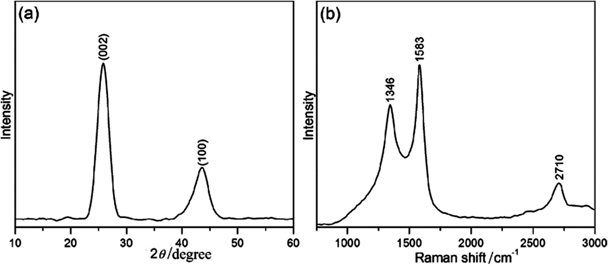 | ||
| Fig. 1 (a) X-ray diffraction pattern and (b) Raman spectrum of freestanding MWCNT foam. | ||
The low-resolution FESEM image of MWCNT foam in Fig. 2a resembles that of pure Ni-foam which is shown in the inset. The etching of Ni foam created 3D hollow channels (Fig. 2b). High-resolution images (Fig. 2c) verified that individual ligaments are composed of 40–50 μm thick CNT forests in which CNTs are aligned vertically, exposed into the three dimensional space, and somewhat densified into clusters, likely caused by solvent evaporation during the etching process.47,48 We also note that this clustering promotes additional hierarchical porosity in the structure. TEM images of the foam (Fig. 2d) indicate that individual CNTs are not strictly parallel; instead the forest consists of bent and kinked CNTs that eventually help to sustain the 3D structure. Such foam like architecture has advantages for improved electrochemical properties for a battery electrode because of better connectivity and conductivity.49,50 It is well known fact that complete removal of PMMA from carbon nanomaterials is quite difficult by conventional technique using IPA. Chen et al. annealed graphene–Ag nanorod film in forming gas to get rid of PMMA.51 Here we have adopted similar technique to completely remove PMMA from MWCNT foam. We have also found residual PMMA under FESEM images of the MWCNT foam before forming gas annealing. Interestingly there was no residual PMMA observed after forming gas annealing at 300 °C. Several defects present in the CNT walls are evident in TEM image in Fig. 2e that likely occurred during the acid-etching of Ni and annealing of the MWCNT foam. A high-resolution TEM image (Fig. 2f) of an individual nanotube clearly shows that the CNT walls are composed of 10–15 layers with a core diameter of 5–8 nm.
 | ||
| Fig. 2 (a–c) FESEM images and (d–f) TEM images of freestanding MWCNT foam at various magnifications. Inset of (a): FESEM image of pure Ni foam. | ||
In order to investigate the chemical composition of the MWCNT foam, X-ray photoelectron spectra have been recorded. The most intense XPS peak at 284.5 eV (Fig. 3a) can be assigned to the C 1s binding energy for graphitic carbon.43 The peak at 532 eV (Fig. 3b) is characteristic of O 1s binding energy.52 The presence of oxygen in MWCNT foam is likely due to the etching process. Defects on the surface and tips of MWCNTs during acid treatment of the sample during Ni etching are more desirable to adsorb oxygen when exposed to air. Similar observation of generation of surface functional groups on CNTs is also reported by Xiong et al.45 The amounts of C and O in the MWCNT foam are 83.4 and 14.3 at%, respectively. Additionally, a small amount (1.4 at%) of partially oxidized Fe remains in the sample (evidenced by Fe 2p3/2 peak at 709.4 eV), arising from the FeCl3 used for Ni etching.53,54 Deconvolution of C 1s (Fig. 3a) and O 1s (Fig. 3b) spectra reveals that the main C 1s peak arises from graphitic C![[double bond, length as m-dash]](https://www.rsc.org/images/entities/char_e001.gif) C bonds between sp2 carbon atoms. There are other peaks related to O atoms bonded to C atoms in different configurations together with or without H atoms (Fig. 3a).43,55 Additionally, the presence of a broad satellite peak around 290.9 eV in the C 1s spectrum (Fig. 3a), reflects the aromatic C rings in MWCNTs excited by the photoelectrons.56 This two-electron process occurs during removing a photoelectron from a parent atom corresponding to energy loss upon excitation of the π → π* transition by a photoelectron in the aromatic graphitic lattice. Therefore, the MWCNTs used for this study are highly graphitic. XPS measurements also demonstrate the complete removal of the Ni template used in the initial growth process. Thus, the MWCNT foams prepared in this study is highly graphitic and rich in surface as well as CNT edge defects. The defect-rich graphitic carbon microstructure is beneficial for Li-ion battery anodes due to additional Li-ion storage in the disordered graphene layers.4,49,57–59
C bonds between sp2 carbon atoms. There are other peaks related to O atoms bonded to C atoms in different configurations together with or without H atoms (Fig. 3a).43,55 Additionally, the presence of a broad satellite peak around 290.9 eV in the C 1s spectrum (Fig. 3a), reflects the aromatic C rings in MWCNTs excited by the photoelectrons.56 This two-electron process occurs during removing a photoelectron from a parent atom corresponding to energy loss upon excitation of the π → π* transition by a photoelectron in the aromatic graphitic lattice. Therefore, the MWCNTs used for this study are highly graphitic. XPS measurements also demonstrate the complete removal of the Ni template used in the initial growth process. Thus, the MWCNT foams prepared in this study is highly graphitic and rich in surface as well as CNT edge defects. The defect-rich graphitic carbon microstructure is beneficial for Li-ion battery anodes due to additional Li-ion storage in the disordered graphene layers.4,49,57–59
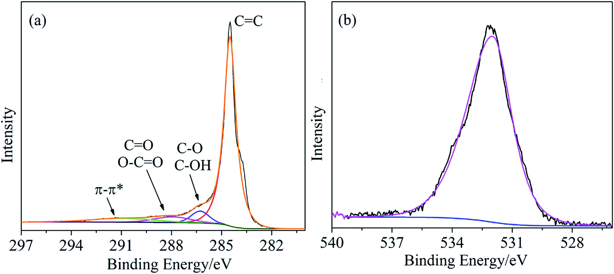 | ||
| Fig. 3 XPS spectra of freestanding MWCNT foam (a) C 1s and (b) O 1s. | ||
Electrochemical performance of 3D freestanding MWCNT foam
To investigate the Li intercalation electrochemical performance of the MWCNT foam, we performed galvanostatic charge–discharge measurements at controlled current densities in the voltage range 0–3 V. Typical voltage profiles of MWCNT foam and commercial graphitic carbon at different current densities are presented in Fig. 4a and b, respectively. Notable differences in the lithiation–delithiation process are evident from the dissimilarities in the shapes of voltage profiles of these carbonaceous electrodes. Discharge profiles of commercial graphite are composed of a plateau around 0.1 V, compared to a sloping profile that spans up to approximately 1 V in the case of MWCNT foam. It is clear that Li-ion storage performance of MWCNT foam is superior to commercial graphite anode. Despite its graphitic nature, lithiation of MWCNT foam occurred at high voltages compared to commercial graphitic carbon. In this case, only 34% of the capacity was achieved below 0.1 V, making it a much safer anode compared to graphitic carbon. A high discharge capacity of 633 mA h g−1 was observed for MWCNT foam at a current density of 0.1C (37.2 mA g−1). Clearly, MWCNT foams are capable of lithiation at higher potentials, and storing more Li ions compared to commercial graphitic carbon due to the defect-rich microstructure.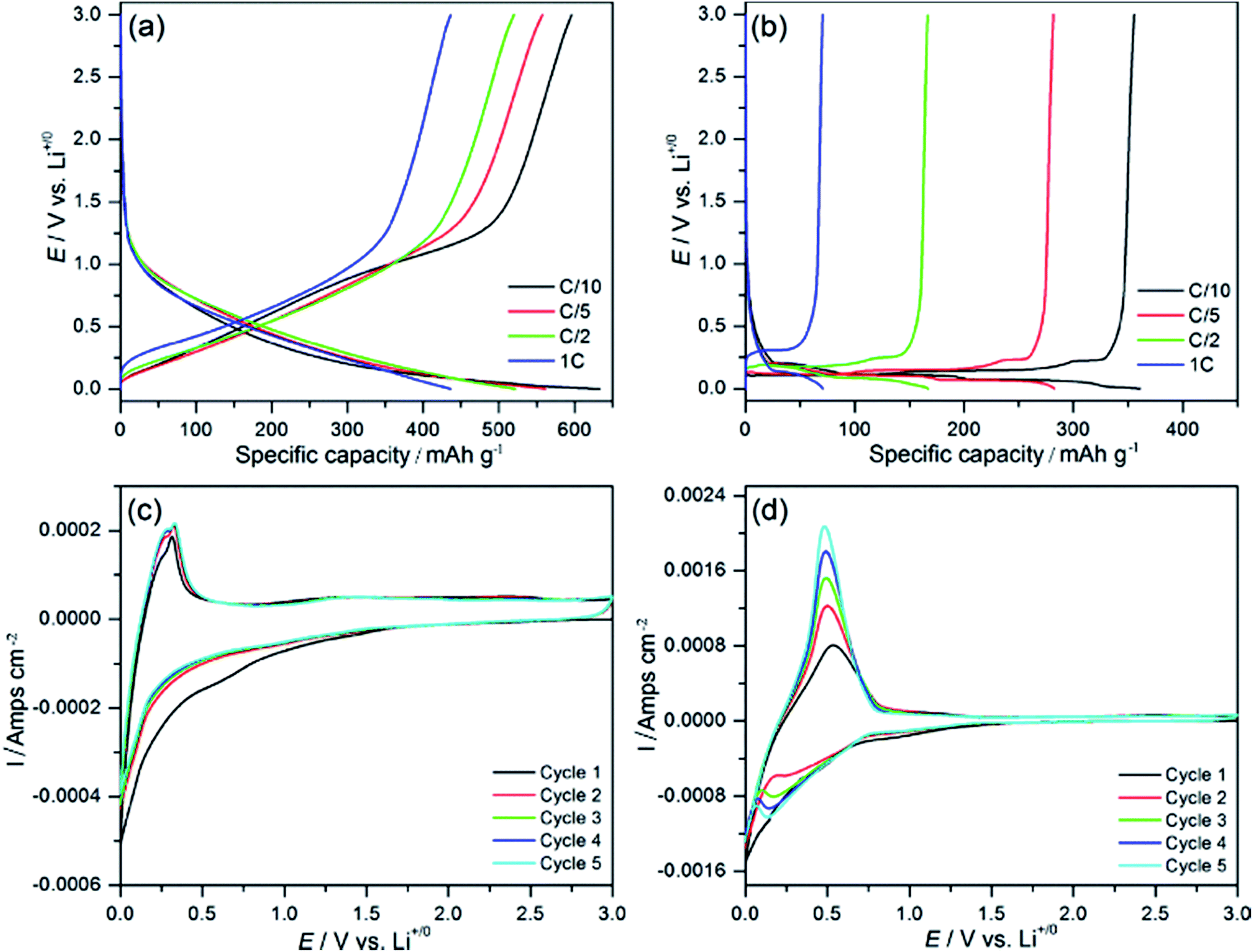 | ||
| Fig. 4 Second charge–discharge profiles of (a) freestanding MWCNT foam, and (b) commercial graphite at various current densities. Cyclic voltammetry of (c) freestanding MWCNT foam and (d) commercial graphite in a Li-ion half-cell (scan rate 1 mV s−1). | ||
Cyclic voltammetry analysis of the carbonaceous electrodes in the 0–3 V voltage range (Fig. 4c and d) was performed to gain further insight into the lithiation–delithiation process. MWCNT foam electrode displayed broader cathodic responses (2.5–0 V) compared to commercial graphite (1.5–0 V) anodes. The sharp cathodic band in the 0–0.25 V range and a shoulder at 0.6 V that are assigned to lithium intercalation into carbon (C6 + Li+ + e− → LiC6) and SEI formation respectively.60 On the second and subsequent cycles, only the cathodic signal corresponding to lithiation of carbon remained, and its shape retention on prolonged cycling implies identical redox processes that could be due to limited consumption of lithium ions from Li metal. In addition, we attribute the cathodic response of MWCNT foam at higher potentials to Li-ion storage at surface defects. The cathodic voltammetry response also correlate very well with the galvanostatic discharge profiles, and demonstrates that only approx. 35% of the total discharge capacity resulted from the graphitic phase of MWCNTs. The anodic signal centered at 0.3 V is characteristic of Li deintercalation from LiC6 (LiC6 → C6 + Li+ + e−). In the case of commercial graphite anodes, sharp cathodic peak centered at 0.13 V (Fig. 4d), correspond to Li-intercalation into ordered graphite structure.61,62 Thus it can be concluded that Li-ion storage mechanism of MWCNT foam is different from that of commercial graphite anodes.
The first charge–discharge cycle of the MWCNT foam (Fig. 5a) at a current density of 0.1C is associated with an irreversible capacity loss (31%) that is common for high surface area anodes, which leads to the formation of slow and excessive secondary electrolyte interphase formation.4,54,56 An ideal rechargeable Li-ion battery should have minimum (<15%) irreversible capacity loss, and efforts are underway to improve this aspect of the material. CNTs typically experience more irreversible capacity loss than graphitic electrodes due to electrolyte reaction with surface defects (resulting from high surface area) or impurities.
 | ||
| Fig. 5 (a) First discharge–charge profiles of MWCNT foam, (b) electrochemical rate performance of MWCNT foam and commercial graphite at various current densities, (c) galvanostatic cycling performance of freestanding MWCNT foam at various current density and (d) EIS of commercial graphite and MWCNT foam. | ||
High rate electrochemical tests (Fig. 5b) were conducted to evaluate the Li-ion intercalation performance of these carbonaceous electrodes at various charge–discharge rates. At C/10, MWCNT foam displayed a discharge capacity of around 600 mA h g−1, which is higher than the commercial graphite anode under similar experimental conditions. Both electrodes experienced a reduction in capacity with increased charge–discharge rates as only limited Li-ion intercalation–deintercalation occurs in short time. Nevertheless, MWCNT foam retained an excellent specific capacity of 420 mA h g−1 at 1C rate. High capacity retention during prolonged cycling (Fig. 5c) was also observed in the case of MWCNT foam, maintaining 790 and 510 mA h g−1 at 0.1C and 1C rate, respectively after 100 galvanostatic cycles. This result is comparable to the specific capacity of many transition metal oxide based Li-ion battery anodes.63–65 Although we tested the MWCNT foam in the 0–3 V range, only 10% of Li-deintercalation occurs above 1.5 V. The slight increase in specific capacity on extended cycling can be attributed to the defects on the CNTs and it could lead to develop more active sites during the lithiation–delithiation process in the wide voltage range (0–3 V).59
To further elucidate the enhanced electrochemical performance of MWCNT foam, we performed electrochemical impedance spectroscopy (EIS) analysis of electrodes at open circuit potential (to avoid the effect of SEI) before galvanostatic cycling (Fig. 5d). EIS patterns are measured and showed for both MWCNT foam and graphite electrodes. The low-frequency linear trend and high-frequency semicircle are characteristic of Li-ion solid-state diffusion (ZW) and charge transfer resistance (Rct), respectively. The primary is the smaller semicircle and reduced solid-state Li-ion diffusion resistance in the case of MWCNT samples. This behaviour can be explained by the 3D morphology, hierarchical porosity and defect rich microstructure of MWCNT foam that facilitate superior electrode–electrolyte contact and solid-state Li-ion diffusion.
Finally, we performed SEM and Raman spectroscopy studies on MWCNT electrodes after 100 galvanostatic cycles for further insights into their structural and chemical stability during lithiation–delithiation cycles. Importantly, the freestanding 3D foam morphology and interconnections between vertically oriented MWCNT forests were maintained during Li-ion battery fabrication process and prolonged cycling (Fig. 6a and b). SEI formation, which is responsible for the first cycle irreversible capacity loss was evident as a uniform thin layer covering the cycled electrode (Fig. 6c). Increased intensity of the Raman D-band (ID/IG = 0.87) of cycled MWCNT foam (Fig. 6d) signifies increased disorder caused by repeated Li-ion intercalation and deintercalation into the graphitic walls of MWCNTs. We attributed this electrochemically induced disorder in the MWCNT to the specific capacity increase on prolonged cycling in the voltage range of 0–3 V. Analogous to current study, MWCNTs are reported with 150 to 200 m2 g−1 specific surface area with 10–20 nm outer diameter and 10–30 micron long MWCNTs.66 Enhanced Li-ion storage electrochemical performance of MWCNT foam can be explained by the disordered microstructure, 3D morphology, and hierarchical porosity. As discussed earlier, disordered carbon microstructure is beneficial for storing more Li-ions in comparison to an ordered graphitic structure. Surface defects formed during the etching process and pores between individual carbon nanotubes could also act as additional Li-ion storage sites. This claim can be substantiated by recent reports of supplemental Li-ion storage mechanisms in carbon anode micropores, defects and disordered interlayers.4,57,58,67 Binder-free, hierarchically porous 3D morphology of MWCNT foam is another factor responsible for the superior electrochemical performance. Submicron channels of the foam facilitate in improving contact with electrolyte solution, allowing fast charge–discharge. In addition, submicron-sized voids also help to accommodate volume change during charge–discharge processes. Moreover, the interconnections between individual CNTs maintain the freestanding 3D morphology, which prevents agglomeration of CNTs during electrochemical cycling to maintain superior electrode–electrolyte contact. The specific capacity increase upon prolonged cycling could result from either increased disorderness of CNTs or due to increased exposure of the active material caused by electrode pulverization. Post-cycling SEM analysis of MWCNT foam proved their excellent mechanical stability and the absence of electrode pulverization (Fig. 6a–c). However Raman analysis (Fig. 6d) proved increased disorderness caused by lithiation–delithiation over the wide voltage range, which can be attributed to the specific capacity increase up on prolonged cycling. Landi et al. have reviewed the Li-ion storage capability of CNT based anode and reported that pristine MWCNT has 210 mA h g−1 Li-ion capacity in freestanding form.68 In an another review, Xiong et al. has mentioned MWCNTs to have maximum Li-ion storage capability of 577 mA h g−1.69 Recently, Kang et al. have demonstrated freestanding 3D CNT fabrication by growing CNTs on Cu mesh through CVD method using ethylene (C2H2) as feed gas. They have reported a Li-ion storage capacity of 397 mA h g−1 at 0.1C current density.70 The demonstrated Li-ion storage capability (790 mA h g−1) with our MWCNT foam is 199% higher than this report (397 mA h g−1), which can be attributed to the unique structure of vertically aligned MWCNTs in the foam, its ultra-high porosity and very low 3D density. The reported Li-ion storage of MWCNT foam can further be improved by metal oxide inclusion.71,72
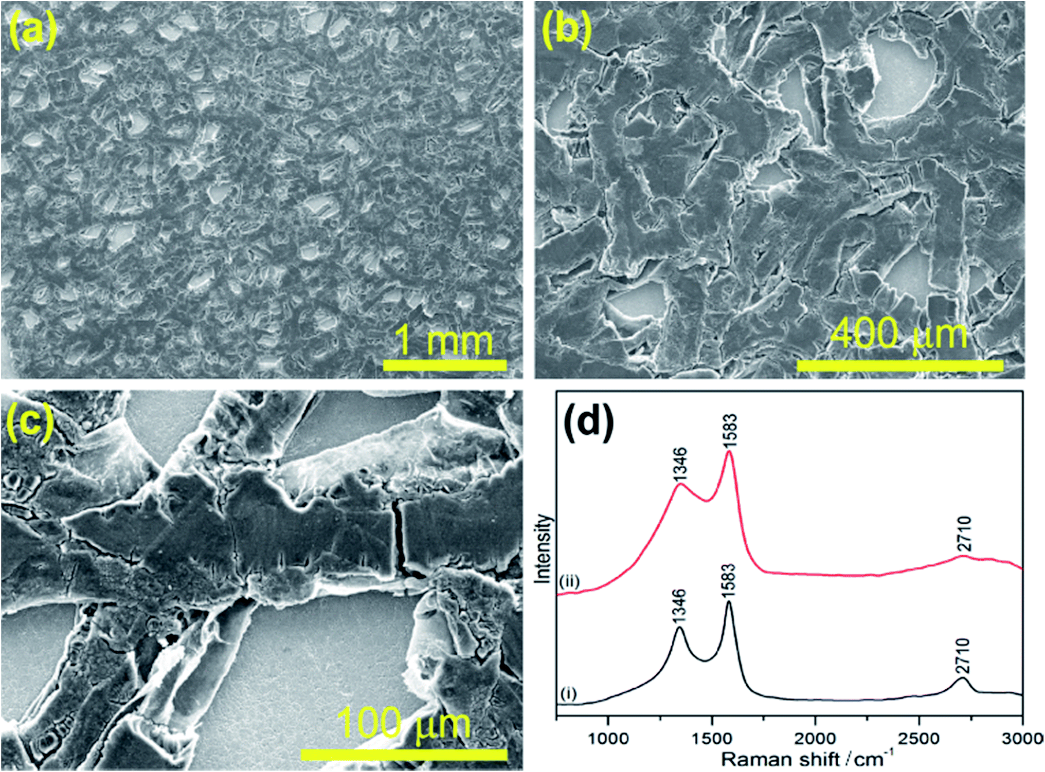 | ||
| Fig. 6 (a–c) SEM images of freestanding MWCNT foam electrodes after 100 galvanostatic cycles, and (d) Raman spectra (i) before, and (ii) after galvanostatic cycling. | ||
Conclusions
We, first time, demonstrated an unique, binderfree 3D foam with vertically aligned CNTs fabricated through microwave plasma assisted chemical vapor deposition. The foam showed promising Li-ion storage performance which was attributed to the easily available structural micropores in foam as well as the defects and disordered interlayers in individual CNT. The foam is 99.8% porous and has ultra-low density of 4 mg cm−3. This substrate free foam consists of vertically oriented interconnected carbon nanotubes resulting in a hierarchically porous microstructure which exhibited enhanced cycling stability, retaining 790 and 510 mA h g−1 after 100 galvanostatic cycling. Improved structural and chemical stability of the foam during charge–discharge cycles has been demonstrated by the post-diagnostic of the battery electrodes after 100 galvanostatic cycles and its study by Raman spectroscopy and scanning electron microscopy. In addition, our 3D MWCNT foam showed 199% improved specific capacity over recently reported freestanding 3D CNT structure. The as-grown foam without any intentional functionalization or hybrid atoms incorporation on its surface shows excellent Li-ion storage which can further be investigated in future towards very useful electrochemical energy storage devices.Acknowledgements
Financial support for this work provided by the MURI program on Nanofabrication of Tunable 3D Nanotube Architectures (PM: Dr Joycelyn Harrison, Grant: FA9550-12-1-0037) is gratefully acknowledged. Authors are also grateful to the staff members of the Birck Nanotechnology Center at Purdue University for their support and cooperation. We are thankful to Dr D. Y. Zemlyanov for helping in recording the XPS spectra and Dr Anurag Kumar for help in recording SEM image of bare Ni foam. VP thanks the Purdue University and School of Chemical Engineering for their generous start-up funding. The ConocoPhillips graphite electrodes used for comparison in this experiment were produced at the U.S. Department of Energy's (DOE) CAMP (Cell Analysis, Modeling and Prototyping) Facility, Argonne National Laboratory. Electron microscopy studies at Purdue's Birck Nanotechnology Center were funded by a Kirk exploratory research grant and Thermo Scientific for DXR Raman microscope facilities. TSF thanks the National Science Foundation's Scalable Nanomanufacturing program (Grant: CMMI-1344654).Notes and references
- A. S. Arico, P. Bruce, B. Scrosati, J. M. Tarascon and W. V. Schalkwijk, Nat. Mater., 2005, 4, 366–377 CrossRef CAS PubMed.
- M. Armand and J. M. Tarascon, Nature, 2008, 451, 652–657 CrossRef CAS PubMed.
- C. K. Chan, H. Peng, G. Liu, K. McIlwrath, X. F. Zhang, R. A. Huggins and Y. Cui, Nat. Nanotechnol., 2008, 3(1), 31–35 CrossRef CAS PubMed.
- V. Etacheri, C. Wang, M. J. O'Connell, C. K. Chan and V. G. Pol, J. Mater. Chem. A, 2015, 3(18), 9861–9868 CAS.
- M. S. Whittingham, Chem. Rev., 2004, 104, 4271–4301 CrossRef CAS PubMed.
- V. Etacheri, J. E. Yourey and B. M. Bartlett, ACS Nano, 2014, 8, 1491–1499 CrossRef CAS PubMed.
- B. Kang and G. Ceder, Nature, 2009, 458, 190–193 CrossRef CAS PubMed.
- S. L. Candelaria, Y. Shao, W. Zhou, X. Li, J. Xiao, J. G. Zhang, Y. Wang, J. Liu, J. Li and G. Cao, Nano Energy, 2012, 1, 195–220 CrossRef CAS.
- I. Lahiri, S. W. Oh, J. Y. Hwang, S. Cho, Y. K. Sun, R. Banerjee and W. Choi, ACS Nano, 2010, 4, 3440–3446 CrossRef CAS PubMed.
- S. H. Yu, X. Guo, D. Ling, D. Y. Chung, A. Jin, M. Shokouhimehr, T. Hyeon and Y. E. Sung, RSC Adv., 2014, 4, 37365–37370 RSC.
- S. Goriparti, E. Miele, F. D. Angelis, E. D. Fabrizio, R. P. Zaccaria and C. Capigli, J. Power Sources, 2014, 257, 421–443 CrossRef CAS.
- Z. Xiong, Y. S. Yun and H. J. Jin, Materials, 2013, 6(3), 1138–1158 CrossRef CAS.
- J. M. Tarascon and M. Armand, Nature, 2001, 414, 359–367 CrossRef CAS PubMed.
- Y. Xing, Y. Wang, C. Zhou, S. Zhang and B. Fang, ACS Appl. Mater. Interfaces, 2014, 6, 2561–2567 CAS.
- B. Fang, M. S. Kim, J. H. Kim, S. Lim and J. S. Yu, J. Mater. Chem., 2010, 20, 10253–10259 RSC.
- M. S. Kim, B. Fang, J. H. Kim, D. Yang, Y. K. Kim, T. S. Bae and J. S. Yu, J. Mater. Chem., 2011, 21, 19362–19367 RSC.
- H. Dai, Surf. Sci., 2002, 500, 218–241 CrossRef CAS.
- B. J. Landi, M. J. Ganter, C. D. Cress, R. A. DiLeo and R. P. Raffaelle, Energy Environ. Sci., 2009, 2, 638–654 CAS.
- R. Carter, L. Oakes, A. P. Cohn, J. Holzgrafe, H. F. Zarick, S. Chatterjee, R. Bardhan and C. L. Pint, J. Phys. Chem. C, 2014, 118(35), 20137–20151 CAS.
- X. M. Liu, Z. Huang, S. W. Oh, B. Zhang, P. M. Ma, M. M. F. Yuen and J. K. Kim, Compos. Sci. Technol., 2012, 72, 121–144 CrossRef CAS.
- J. Hou, Y. Shao, M. W. Ellis, R. B. Moore and B. Yi, Phys. Chem. Chem. Phys., 2011, 13, 15384–15402 RSC.
- X. Li, F. Kang, X. Bai and W. Shen, Electrochem. Commun., 2007, 9, 663–666 CrossRef CAS.
- X. Meng, S. C. Riha, J. A. Libera, Q. Wu, H. H. Wang, A. B. F. Martinson and J. W. Elam, J. Power Sources, 2015, 280, 621–629 CrossRef CAS.
- S. Yoon, S. Lee, S. Kim, K. W. Park, D. Cho and Y. Jeong, J. Power Sources, 2015, 279, 495–501 CrossRef CAS.
- Y. He, L. Huang, J. S. Cai, X. M. Zheng and S. G. Sun, Electrochim. Acta, 2010, 55, 1140–1144 CrossRef CAS.
- H. Lin, W. Weng, J. Ren, L. Qiu, Z. Zhang, P. Chen, X. Chen, J. Deng, Y. Wang and H. Peng, Adv. Mater., 2014, 26, 1217–1222 CrossRef CAS PubMed.
- X. X. Wang, J. N. Wang, H. Chang and Y. F. Zhang, Adv. Funct. Mater., 2007, 17, 3613–3618 CrossRef CAS.
- H. X. Zhang, C. Feng, Y. C. Zhai, K. L. Jiang, Q. Q. Li and S. S. Fan, Adv. Mater., 2009, 21, 2299–2304 CrossRef CAS.
- L. Hua, J. W. Choi, Y. Yang, S. Jeong, F. L. Manti, L. F. Cui and Y. Cui, Proc. Natl. Acad. Sci. U. S. A., 2009, 106, 21490–21494 CrossRef PubMed.
- Z. P. Chen, W. C. Ren, L. B. Gao, B. L. Liu, S. F. Pei and H. M. Cheng, Nat. Mater., 2011, 10, 424–428 CrossRef CAS PubMed.
- X. C. Dong, Y. F. Cao, J. Wang, M. B. Chan-Park, L. H. Wang, W. Huang and P. Chen, RSC Adv., 2012, 2, 4364–4369 RSC.
- X. C. Dong, H. Xu, X. W. Wang, Y. X. Huang, M. B. Chan-Park, H. Zhang, L. H. Wang, W. Huang and P. Chen, ACS Nano, 2012, 6, 3206–3213 CrossRef CAS PubMed.
- X. Dong, Y. Ma, G. Zhu, Y. Huang, J. Wang, M. B. C. Park, L. Wang, W. Huang and P. Chen, J. Mater. Chem., 2012, 22, 17044–17048 RSC.
- Y. C. Yong, X. C. Dong, M. B. Chan-Park, H. Song and P. Chen, ACS Nano, 2012, 6, 2394–2400 CrossRef CAS PubMed.
- X. Wang, G. Sun and P. Chen, Front. Energy Res., 2014, 2, 1–8 Search PubMed.
- N. Zhao and J. Kang, Direct growth of carbon nanotubes on metal supports by chemical vapor deposition, Carbon nanotubes - synthesis, characterization, applications, ed. S. Yellampalli, InTech Publisher, 2011, ISBN: 978-953-307-497-9, pp. 99–120 Search PubMed.
- C. D. Casas and W. Li, J. Power Sources, 2012, 208, 74–85 CrossRef.
- J. C. Guo, Y. H. Xu and C. S. Wang, Nano Lett., 2011, 11, 4288–4294 CrossRef CAS PubMed.
- H. Kim, K. Y. Park, J. Hong and K. Kang, Sci. Rep., 2014, 4(5278), 1–8 CAS.
- A. S. Kousalya, C. N. Hunter, S. A. Putnam, T. Miller and T. S. Fisher, Appl. Phys. Lett., 2012, 100, 071601 CrossRef.
- K. R. Saviers, S. L. Hodson, T. S. Fisher, J. R. Salvador and L. S. Kasten, J. Thermophys. Heat Transfer, 2013, 27, 474–481 CrossRef CAS.
- R. Paul, D. Y. Zemlyanov, A. A. Voevodin, A. K. Roy and T. S. Fisher, Thin Solid Films, 2014, 572, 169–175 CrossRef CAS.
- R. Paul, A. A. Voevodin, D. Zemlyanov, A. K. Roy and T. S. Fisher, Adv. Funct. Mater., 2012, 22, 3682–3690 CrossRef CAS.
- L. Bokobza and J. Zhang, eXPRESS Polym. Lett., 2012, 6(7), 601–608 CrossRef CAS.
- Z. Xiong, Y. S. Yun and H. J. Jin, Materials, 2013, 6, 1138–1158 CrossRef CAS.
- S. Klinka, E. Ventosa, W. Xia, F. L. Mantia, M. Muhler and W. Schuhmanna, Electrochem. Commun., 2012, 15, 10–13 CrossRef.
- A. Qiu and D. F. Bahr, Carbon, 2013, 55, 335–342 CrossRef CAS.
- P. P. S. S. Abadi, M. R. Maschmann, S. Mortuza, S. Banerjee, J. W. Baur, S. Graham and B. A. Cola, Carbon, 2014, 69, 178–187 CrossRef.
- S. Huang, W. Fan, X. Guo, F. Meng and X. Liu, ACS Appl. Mater. Interfaces, 2014, 6(23), 21567 CAS.
- A. Kumar, M. R. Maschmann, S. L. Hodson, J. Baur and T. S. Fisher, Carbon, 2015, 84, 236–245 CrossRef CAS.
- R. Chen, S. R. Das, C. Jeong, M. R. Khan, D. B. Janes and M. A. Alam, Adv. Funct. Mater., 2013, 23, 5150–5158 CrossRef CAS.
- R. Paul, A. A. Voevodin, J. J. Hu, P. B. Amama, S. Ganguli, A. K. Roy, D. Zemlyanov and T. S. Fisher, Thin Solid Films, 2013, 528, 187–193 CrossRef CAS.
- Q. Fu, Y. Yao, X. Guo, M. Wei, Y. Ning, H. Liu, F. Yang, Z. Liu and X. Bao, Phys. Chem. Chem. Phys., 2013, 15, 14708–14714 RSC.
- R. Paul, R. G. Reifenberger, T. S. Fisher and D. Y. Zemlyanov, Chem. Mater., 2015, 27(17), 5915–5924 CrossRef CAS.
- B. P. Payne, M. C. Biesinger and N. S. McIntyre, J. Electron Spectrosc. Relat. Phenom., 2011, 184, 29–37 CrossRef CAS.
- K. A. Wepasnick, B. A. Smith, J. L. Bitter and D. H. Fairbrother, Anal. Bioanal. Chem., 2010, 396(3), 1003–1014 CrossRef CAS PubMed.
- V. Etacheri, C. N. Hong and V. G. Pol, Environ. Sci. Technol., 2015, 49, 11191–11198 CrossRef CAS PubMed.
- K. Sato, M. Noguchi, A. Demachi, N. Oki and M. A. Endo, Science, 1994, 64, 556–558 Search PubMed.
- V. G. Pol and M. M. Thackeray, Energy Environ. Sci., 2011, 4, 1904–1912 CAS.
- T. Zheng and J. R. Dahn, Synth. Met., 1995, 73, 1–7 CrossRef CAS.
- H. Fujimoto, J. Power Sources, 2010, 195, 5019–5024 CrossRef CAS.
- L. Wang, Z. Schnepp and M. M. Titirici, J. Mater. Chem. A, 2013, 1, 5269–5273 CAS.
- V. Etacheri, G. A. Seisenbaeva, J. Caruthers, G. Daniel and J. M. Nedelec, Adv. Energy Mater., 2015, 5(5), 1401289 CrossRef.
- Z. Wang, L. Zhou and X. W. Lou, Adv. Mater., 2012, 24, 1903–1911 CrossRef CAS PubMed.
- J. Jiang, Y. Li, J. Liu, X. Huang, C. Yuan and X. W. Lou, Adv. Mater., 2012, 24, 5166–5180 CrossRef CAS PubMed.
- M. E. Birch, A. Toni, A. T. A. Ruda-Eberenz, M. Chai, R. Andrews and R. L. Hatfield, Ann. Occup. Hyg., 2013, 57(9), 1148–1166 CrossRef CAS PubMed.
- W. Q. Tian, X. Y. Wu, K. X. Wang, Y. M. Jiang, J. F. Wang and J. S. Chen, RSC Adv., 2013, 3, 10823–10827 RSC.
- B. J. Landi, M. J. Ganter, C. D. Cress, R. A. DiLeo and R. P. Raffaelle, Energy Environ. Sci., 2009, 2, 638–654 CAS.
- Z. Xiong, Y. S. Yun and H. J. Jin, Materials, 2013, 6, 1138–1158 CrossRef CAS.
- C. Kang, E. Cha, R. Baskaran and W. Choi, Nanotechnology, 2016, 27, 105402 CrossRef PubMed.
- X. Hou, X. Wang, L. Yao, S. Hu, Y. Wu and X. Liu, New J. Chem., 2015, 39, 1943–1952 RSC.
- L. Yao, X. Hou, S. Hu, J. Wang, M. Li, C. Su, M. O. Tade, Z. Shao and X. Liu, J. Power Sources, 2014, 258, 305–313 CrossRef CAS.
Footnotes |
| † These authors contributed equally. |
| ‡ Present address: Senior Research Associate, Department of Macromolecular Science and Engineering, Case Western Reserve University, Cleveland, Ohio 44106, USA. |
| § Present address: IMDEA Materials Institute, C/Eric Kandel 2, Getafe, Madrid 28906, Spain. |
| This journal is © The Royal Society of Chemistry 2016 |