
Magnetic field-induced fabrication of Fe3O4/graphene nanocomposites for enhanced electrode performance in lithium-ion batteries†
Huan Wanga,
Jingyi Xiea,
Marissa Follettea,
Tyson C. Backb and
Placidus B. Amama*a
aDepartment of Chemical Engineering, Kansas State University, Manhattan, KS 66506, USA. E-mail: pamama@ksu.edu
bMaterials and Manufacturing Directorate, Air Force Research Laboratory, Wright-Patterson Air Force Base, OH 45433, USA
First published on 22nd August 2016
Abstract
We report a novel magnetic field-induced approach for the fabrication of nanoporous and wrinkled Fe3O4/reduced graphene oxide (RGO) anode materials for lithium ion batteries (LIBs). The applied magnetic field improves the interfacial contact between the anode and current collector and increases the stacking density of active material. This facilitates the kinetics of Li ions and electrons, electrode durability, and surface area of active material. As a result, at relatively low specific currents (157 mA g−1), wrinkled Fe3O4/RGO anodes show high reversible specific capacities (up to 903 mA h g−1 at 157 mA g−1). At high discharge rate (1.57 A g−1), the specific capacity of wrinkled anodes stay at 345 mA h g−1 (with capacity retention of 90%) after 100 discharge/charge cycles compared to the rapid capacity fading associated with smooth or unwrinkled anodes with a specific capacity of 178 mA h g−1 after the same number of cycles. These results demonstrate the benefit of strong magnetic field treatment during fabrication of nanocomposites containing magnetic nanoparticles.
1. Introduction
Lithium-ion batteries (LIBs) are a promising energy storage technology for solving the global energy demand due to their high energy content, rechargeability, no memory effect, and environmental friendliness.1,2 However, current LIBs still lack a favorable combination of high rate capability, high energy density, and durability, which has negatively impacted many important applications including portable electronic devices and electric vehicles. The energy density of LIBs depends mainly on the properties of the electrode materials, such as the electrical conductivity, electrochemical window and the ability to accommodate Li ions, whereas the power density, a major limitation of LIBs, is largely dependent on the internal architecture of electrode materials.In comparison to conventional 2D graphite anode,3–6 3D graphene-based anodes exhibit improved rate capabilities due to the short ion pathway, porous structure, high electrical conductivity and buffer region that accommodates the volume expansion of metal oxide nanoparticles during cycling.7–9 Among metal oxide active materials, Fe3O4 has attracted significant attention because of its low cost, nontoxicity, high corrosion resistance, and high natural abundance. However, Fe3O4-based anode materials usually exhibit rapid capacity fading, poor cyclability and limited rate capability due to their low electrical and ionic conductivity as well as their large volume changes during cycling. The use of graphene as an electrode component to overcome the poor cycling performance of Fe3O4 is often plagued by the inevitable tendency of the graphene sheets to restack due to the van der Waals interactions of the sheets especially during conversion from graphene oxide (GO) to reduced graphene oxide (RGO), thus reducing its electrochemically active surface area. To overcome these problems, various strategies have been implemented including optimizing the nanoparticle morphology10,11 and combining Fe3O4 with a nanocarbon material [carbon nanotubes (CNTs), graphene, carbon shells, etc.]8,9,12–16 or via a “double protection strategy” whereby multiple nanocarbons17 are used to improve the stability and cycling performance of Fe3O4.
The use of magnetic field appears to be an effective approach for fabricating high-performance Fe3O4/nanocarbon anodes. Zhang et al.18 demonstrated self-assembly of magnetite hybrid paper at the water–air interface, with the help of an external magnet; the resulting Fe3O4/RGO hybrid anode showed high reversible capacity with long cyclability. The alignment of Fe3O4 nanoparticles along the magnetic field lines has also been used to design Fe3O4/nanocarbon materials. Using a magnetic field induced solvothermal method, Wang et al.16 synthesized Fe3O4/C composite microrods that delivered a stable discharge capacity of about 400 mA h g−1 at a high current density of 1000 mA g−1. However, these methods still require conductive additives and polymer binders to maintain the integrity of anode materials during long cycling, which usually complicates the synthesis process and reduces the anode capacity.
In this study, we demonstrate a simple, facile, and scalable approach to fabricate porous wrinkled Fe3O4/RGO anodes (W-Fe3O4/RGO) that show high reversible capacity, excellent cyclic stability, and better rate capability in LIBs compared to unwrinkled Fe3O4/RGO (U-Fe3O4/RGO). The W-Fe3O4/RGO anodes were prepared by dip coating of Fe3O4/RGO solution on a current collector immediately followed by the application of a strong magnetic field and calcination at 550 °C. The exposure to magnetic field induces alignment and folding of RGO sheets along the magnetic field lines and the formation of a porous 3D structure that promote faster electrons and Li ions transport within the electrode and improve the effective surface area of active materials. The W-Fe3O4/RGO nanocomposites show promise in resolving the capacity-fading problem associated with Fe3O4-based electrodes. To the best of our knowledge, this is the first report that exploits the magnetic properties of Fe3O4 for improving the formation of wrinkled RGO nanosheets by exposure to a supermagnet.
2. Experimental section
2.1. Synthesis of Fe3O4/GO nanocomposites
GO was synthesized from natural flake graphite by the modified Hummers method.19 200 mg of GO was suspended in 200 mL ultrapure water and then sonicated at room temperature for 2 h to form stable GO dispersions. To decorate Fe3O4 nanoparticles uniformly on GO sheets, the Fe3O4/GO nanocomposites were prepared by an in situ chemical method using as-synthesized GO/water dispersion as the precursor. 259.6 mg FeCl2·4H2O and 708.4 mg FeCl3·4H2O were added to GO dispersion (70 mL of 1 mg mL−1) at 80 °C under N2 atmosphere. The blended solution was then stirred for 10 min, quickly followed by addition of 3 mL of 29 wt% ammonium hydroxide. The pH of the final mixture was controlled in the range of 11–12. The reaction was carried out at 80 °C for 30 min under constant mechanical stirring and N2 gas flow. The as-prepared Fe3O4 dispersions were rinsed extensively with ultrapure water and transferred in situ to copious amount of ultrapure water to obtain 1.0 mg mL−1 Fe3O4/GO dispersion.2.2. Preparation of Fe3O4–citric acid/GO ethanol dispersion
20 mg of citric acid was added to 20 mL of the synthesized Fe3O4/GO (1.0 mg mL−1) and sonicated at room temperature for 1 h to form coordinate bonds between Fe3O4 and citric acid. The as-prepared Fe3O4–citric acid/GO was washed with ethanol and then transferred to 20 mL ethanol to form stable Fe3O4–citric acid/GO composites that are dispersed in ethanol.2.3. Preparation of wrinkled Fe3O4/RGO anodes
A piece of copper current collector (9 μm thick) was placed at the center of a round super strong magnet with a maximum pull force of 590 lbs. The as-prepared Fe3O4–citric acid/GO dispersion (3–4 mL) were drop cast on the current collector and dried at room temperature. Thereafter, the dried Fe3O4/GO was annealed at 550 °C for 2 hours in argon atmosphere to reduce GO to RGO. The synthesis steps for the wrinkled Fe3O4/RGO are illustrated in Fig. 1. For the purpose of comparison, the unwrinkled Fe3O4/RGO electrode was prepared following the same steps except that the sample was not subjected to the magnetic field treatment step.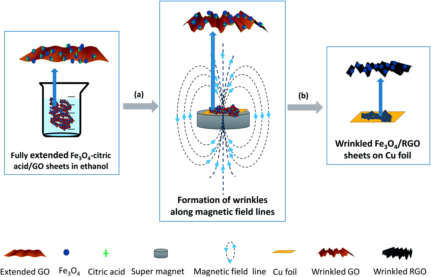 | ||
| Fig. 1 Schematic illustration of synthesis of wrinkled Fe3O4/RGO anode via magnetic field-assisted process followed by annealing in Ar. (a) Deposition of Fe3O4–citric acid/GO ethanol solution on copper foil by dip coating. (b) Annealing of the wrinkled Fe3O4–citric acid/GO anode on copper foil at 550 °C in Ar for 2 hours. | ||
2.4. Materials characterization
The XRD patterns were collected on a Rigaku Miniflex II X-ray diffractometer with Cu Kα radiation (λ = 1.5418 Å) at 40 kV and 40 mA. The morphological characterization of the samples was conducted using a field emission scanning electron microscope (FESEM, Hitachi S5200) and a transmission electron microscope (TEM, FEI Talos). During SEM imaging, the sample composition was determined by energy dispersive spectroscopy (EDS). For TEM imaging, a small amount of Fe3O4/RGO sample was dispersed in isopropanol via ultrasonication; a drop of the homogeneous suspension was deposited on a holey carbon TEM grid and examined by TEM at 120 and 200 kV. X-ray photoelectron spectroscopy (XPS) measurements were performed on a Kratos Ultra XPS system (Kratos, Kanagawa, Japan) with a monochromatic Al Kα source (hν = 1486.6 eV). A charge neutralizer was used to reduce the effect of charging. The analysis of the XPS spectra was performed using Casa XPS software; the least square fitting of the spectra was performed using mixed Gaussian–Lorentzian peak components in the quantification process. Thermogravimetric analysis (TGA) was performed on a Q500 TGA analyzer (TA Instruments) under a stream of air flow (100 sccm) with a temperature ramp of 5 °C min−1 from room temperature to 900 °C.2.5. Electrochemical measurements
The half-cell assembly was carried out in an argon-filled glovebox with concentrations of moisture and oxygen below 50 ppm. The as-prepared wrinkled or unwrinkled Fe3O4/GO nanocomposite on the Cu foil current collector was used as anodes for cells. Microporous polypropylene membrane was used as the separator, and Li foil was used as the counter electrode. The electrolyte used was 1 M LiPF6 dissolved in an ethylene carbonate (EC)/dimethyl carbonate (DMC)/diethyl carbonate (DEC) mixture (1![[thin space (1/6-em)]](https://www.rsc.org/images/entities/char_2009.gif) :1:1, in wt%). Galvanostatic cycling experiments of the cells were performed on a Maccor 4300 battery test system in the voltage range of 0.001–3.00 V versus Li+/Li at room temperature.
:1:1, in wt%). Galvanostatic cycling experiments of the cells were performed on a Maccor 4300 battery test system in the voltage range of 0.001–3.00 V versus Li+/Li at room temperature.
3. Results and discussion
The synthetic procedure of W-Fe3O4/RGO anode is schematically shown in Fig. 1. The first step involves in situ deposition of Fe3O4 nanoparticles on the dispersed GO sheets. The well-dispersed Fe3O4/GO sheets in ethanol obtained by adding citric acid was stabilized by the –COOH groups of the citric acid coordinated to the Fe3O4 nanoparticles. In the second step, dip coating of Fe3O4/GO solution on a copper foil current collector and immediate exposure of the coated solution to a strong magnetic field resulted in wrinkled Fe3O4/GO sheets on the copper foil. The Fe3O4/GO sheets can be dragged up or folded along magnetic field lines as illustrated in Fig. 1. The magnetic field lines near the top surface of the magnet are vertically oriented, thus the magnetic nature of Fe3O4 will force the RGO sheets to form wrinkled structure along the direction of magnetic lines. Following annealing treatment at 550 °C to reduce the GO sheets according to a recipe described in the experimental section, W-Fe3O4/RGO anodes are formed. The structure and phase purity of the synthesized Fe3O4/RGO nanocomposites were characterized by XRD. Fig. 2a shows XRD patterns of Fe3O4/RGO nanocomposites, RGO, and pure Fe3O4 nanoparticles. The profile for RGO shows a broad peak around 2θ degrees of 20–30° that is attributed to defects in RGO.20 Also, the absence of the typical (002) peak of GO ∼12.3° in the XRD profile of RGO21 is a strong evidence of the successful reduction of GO to RGO via thermal treatment. The XRD profile of the as-prepared Fe3O4 nanoparticles is well indexed to magnetite or face-centered cubic Fe3O4 (JCPDS no. 63-3107), suggesting the absence of other phases. In particular, all of the identified XRD peaks of Fe3O4/RGO obtained after annealing treatment can be indexed to fcc Fe3O4 and RGO components. The crystallite size, calculated from the (311) reflection using the Debye–Scherrer formula, is 10.5 nm. The Raman spectra in Fig. 2b show the characteristic peaks of carbonaceous materials at 1601 cm−1 (G-band), 1350 cm−1 (D-band), and the modulated bump ∼2700 cm−1 (2D region). The G-band is associated with graphite in-plane stretching vibrations of sp2 carbon atoms with E2g symmetry while the D-band is assigned to the A1g mode of sp3 carbon atoms in disordered graphite. The integrated intensity ratio of the D- and G-bands (ID/IG = 1.25) of RGO is higher than that of GO (ID/IG = 0.81). This demonstrates restoration of sp2 carbon, as well as an increase in the number of smaller graphene domains, edge planes, and disorder upon reduction of GO.22,23 The inset in Fig. 2b show a weak Raman signal of Fe3O4 at ∼688 cm−1. The Raman results are consistent with the XRD profiles and provide evidence of the successful synthesis of Fe3O4/RGO. | ||
| Fig. 2 (a) XRD patterns of RGO, pure Fe3O4 nanoparticles, and as-synthesized Fe3O4/RGO nanocomposite. (b) Raman spectra of GO, RGO and Fe3O4/RGO nanocomposite. (c) XPS survey scan of Fe3O4–RGO nanocomposite. (d) TGA curve of Fe3O4/RGO nanocomposite under airflow at a temperature ramp of 5 °C min−1. | ||
The synthesized Fe3O4/RGO nanocomposites were further characterized by EDS, XPS, and TGA to determine their chemical composition. The EDS spectrum of Fe3O4/RGO (Fig. S1†) has three main peaks that indicate the presence of C, Fe, and O, and two small peaks that are attributed to N and Cu. The XPS survey scan in Fig. 2c corroborates the presence of C 1s, O 1s, and Fe 2p peaks with Fe/C atomic ratio of 0.46, estimated from C 1s and Fe 2p peaks for Fe3O4/RGO; the detailed elemental compositions are also presented in Fig. 2c and Table S2.† From the TGA profile in Fig. 2d, the weight percentage of Fe3O4 in Fe3O4/RGO nanocomposite is determined to be 85.9 wt%. The initial weight loss below 200 °C is most likely associated with the removal of moisture and volatile organics. However, the actual weight percentage of Fe3O4 in Fe3O4/RGO (83.03 wt%) was used in the calculation of specific capacity. The slightly weight gain (2.87%) is due to the oxidation process of Fe3O4 to Fe2O3 during TGA analysis in air.24,25
The morphology of the as-synthesized Fe3O4/RGO anodes was examined using a FESEM. Panels a and b in Fig. 3 are low and high magnification FESEM images of U-Fe3O4/RGO electrode, respectively. This sample was synthesized without exposure to a magnetic field. The images show Fe3O4 nanoparticles, with average diameter of 10 nm, forming a relatively smooth and unaligned morphology on RGO structures. In some areas, the RGO sheets are observed partially covering the Fe3O4 nanoparticles (see red lines in Fig. 3, panel a). The representative high magnification image in panel b shows that the Fe3O4 nanoparticles experience severe aggregation during the fabrication process without the magnetic field treatment. The aggregation of electrode nanoparticles has been shown to induce capacity fading and loss of electrical contact between electrodes and current collectors.26,27 A common approach for preventing aggregation in nanocomposites is the addition of a dispersant or coating with graphene or carbon layers,28,29 which usually require careful control and extensive optimization of the fabrication steps. In contrast to the unwrinkled samples prepared without magnetic treatment, Fig. 3 shows low (panels c and e) and high magnification (panels d and f) images of W-Fe3O4/RGO electrodes exposed to a strong magnetic field during the synthesis process. Because of the drag-up force along magnetic field lines, W-Fe3O4/RGO show curled and wrinkled morphologies with Fe3O4 nanoparticles decorated on ridged RGO sheets. The zoomed-in images in Fig. 3 (panels d and f) show that the Fe3O4 nanoparticles are well dispersed on the wrinkled RGO sheets. The W-Fe3O4/RGO nanocomposites are characterized by a nanoporous structure with randomly organized pores and a non-agglomerated morphology, and are well adapted to facilitate the lithium insertion and extraction kinetics due to the reduced diffusion distance,30 as well as accommodate the strain caused by the severe volume expansion of Fe3O4 nanoparticles. Therefore, our highly porous and wrinkled Fe3O4/RGO anode is well suited for supplying rapid transport pathways for both lithium ions and electrons, thus enhancing the rate capability.
 | ||
| Fig. 3 FESEM images of wrinkled and unwrinkled Fe3O4/RGO anodes. (a and b) Low and high magnification images of U-Fe3O4/RGO anodes synthesized without magnetic field treatment. (c and d) Low and high magnification images of W-Fe3O4/RGO anodes subjected to magnetic field and centrifugation treatments during synthesis (centrifugation at 6000 rpm for 15 min). (e and f) Low and high magnification images of W-Fe3O4/RGO anodes exposed to magnetic field without centrifugation. | ||
Fig. 3 also reveal that the centrifugation conditions of the Fe3O4–citric acid/GO ethanol solution affected the formation of the wrinkled Fe3O4/RGO structures on the copper substrate. The two W-Fe3O4/RGO samples shown in panels c and d (Sample-1) and e and f (Sample-2) are compared. Both samples were synthesized using the same procedure except that Sample-1 was subjected to centrifugation at 6000 rpm (∼2414g force) for 15 min while Sample-2 was not. The vertical folding/orientation of RGO sheets in panels e and f (Sample-2) is higher than the sheets in Sample-1. The difference in wrinkles can be observed more clearly in the zoomed-in images in panels d and f. We hypothesize that the well-dispersed Fe3O4–citric acid/GO sheets may be experiencing re-aggregation under high-speed centrifugation, which could impede the folding/orientation of Fe3O4–citric acid/GO sheets. Our findings show that the use of Fe3O4–citric acid/GO ethanol solution that has not been subjected to centrifugation yields highly wrinkled Fe3O4/RGO anodes, as further verified by FESEM (see images presented in Fig. S3†).
Further evaluation of the morphology of the as-synthesized Fe3O4–RGO was carried out by TEM (Fig. 4). The Fe3O4 nanoparticles are non-agglomerated and highly uniform in size (panel a). Evidence of Fe3O4 nanoparticles in contact with RGO sheets is shown in panel b. From the TEM images, the average size of Fe3O4 nanoparticles is about 10 nm, which is consistent with the calculated value from XRD using the Debye–Scherrer equation. The zoomed-in high-resolution TEM image of panel c (panel d) shows well-resolved lattice fringes with an interlayer distance of 0.25, corresponding to the (311) plane of Fe3O4.
 | ||
| Fig. 4 TEM images of Fe3O4/RGO. (a) Low-magnification image showing Fe3O4 nanoparticles. (b) Fe3O4 nanoparticles in contact with RGO. (c and d) High-resolution images of Fe3O4 nanoparticles. | ||
The high-resolution XPS spectra for Fe 2p and C 1s for wrinkled and unwrinkled samples are shown in Fig. 5. The Fe 2p3/2 and 2p1/2 are positioned at binding energies of 711.3 and 724.9 eV, respectively; the broadening of these peaks is evidence of the presence of a Fe2+ and Fe3+ or Fe3O4, which is a mixed state of FeO and Fe2O3 and confirms that Fe in the synthesized nanocomposite exist in Fe3O4 state. We note that the satellite peak of Fe 2p3/2 is used to identify the different oxidation states; Fe2+ and Fe3+ have satellite peaks at 715 and 719 eV, respectively.23 There is a small peak at ∼719 eV for both the wrinkled and unwrinkled samples (Fig. 5a), indicating the existence of small amount of Fe2O3 in our samples. The deconvolution of the C 1s peak (Fig. 5b) reveals the presence of three types of carbon species: C–C (284.5 eV), C–O (286.8 eV), and C![[double bond, length as m-dash]](https://www.rsc.org/images/entities/char_e001.gif) O (287.7 eV). The C–C peak is attributed to the carbonaceous species from RGO while the oxygen-containing species, C–O and CO (carbonyl), are features that are associated with GO and Fe–RGO linkages. The respective carbon atomic compositions of C–C, C–O, and CO for W-Fe3O4/RGO are 41.1, 39.3, and 19.7 at% while the compositions for the U-Fe3O4/RGO are 40.8, 37.7, and 21.4 at%, respectively. Therefore, from the FESEM images (Fig. 3) and the XPS results (Fig. 5), it can be concluded that while the surface chemistries of the wrinkled and unwrinkled samples are highly identical, their morphologies, in terms of their wrinkles, are markedly different.
O (287.7 eV). The C–C peak is attributed to the carbonaceous species from RGO while the oxygen-containing species, C–O and CO (carbonyl), are features that are associated with GO and Fe–RGO linkages. The respective carbon atomic compositions of C–C, C–O, and CO for W-Fe3O4/RGO are 41.1, 39.3, and 19.7 at% while the compositions for the U-Fe3O4/RGO are 40.8, 37.7, and 21.4 at%, respectively. Therefore, from the FESEM images (Fig. 3) and the XPS results (Fig. 5), it can be concluded that while the surface chemistries of the wrinkled and unwrinkled samples are highly identical, their morphologies, in terms of their wrinkles, are markedly different.
 | ||
| Fig. 5 High-resolution XPS spectra of Fe 2p (a) and C 1s (b) for wrinkled and unwrinkled Fe3O4/RGO anodes and their related curve fitted components. | ||
The W-Fe3O4/RGO electrode material was first evaluated by cyclic voltammograms (CV) between 0.001 and 3.0 V at a scan rate of 0.1 mV s−1. Fig. 6a shows the reduction and oxidation peaks in the first four complete scans. In general, the CV results for the W-Fe3O4/RGO electrode are consistent with previously reported results for Fe3O4-based electrodes.9,10,12,31 In the first cathodic scan, two well-defined peaks are observed at 0.60 and 0.02 V, which are attributed to the reduction of Fe3O4 to Fe0 (by the reaction: Fe3O4 + 8Li+ + 8e− ↔ 3Fe0 + 4Li2O) and lithium ions insertion in the RGO sheets, respectively. Meanwhile, the anodic peaks between 1.6 and 2.0 V correspond to the reversible oxidation of Fe0 to Fe2+ and Fe3+. In subsequent CV scans, the anodic curves were very similar to the first anodic curve whereas the subsequent cathodic curves are quite distinguishable from the first scan. The cathodic peaks shifted from 0.60 to 0.78 V, revealing structural modifications during the first scan. Moreover, the decreased intensity of the cathodic peaks compared to the 0.60 V peak in the first cathodic scan and the appearance of new peaks at 1.5 V, indicate the occurrence of some irreversible reactions with formation of an SEI layer. It should be emphasized that the cathodic and anodic profiles seem to overlap after the second scan, which indicates the high stability of the W-Fe3O4/RGO anodes during cycling.
 | ||
| Fig. 6 (a) Cyclic voltammograms for the first 4 cycles of W-Fe3O4/RGO anode at a scan rate of 0.1 mV s−1 in the potential window of 3.0–0.001 V (vs. Li/Li+). (b) Selected discharge–charge profiles (1st, 2nd, 3rd, 50th, and 100th cycle) of W-Fe3O4/RGO anode at a cycling rate of 0.2C. (c) Cycling performances of RGO and W-Fe3O4/RGO anodes at 0.2C. The coulombic efficiency of W-Fe3O4/RGO anode is also displayed (blue curve). (d) Cycling performance of W-Fe3O4/RGO and U-Fe3O4/RGO anodes at different cycling rates of 0.2C, 0.5C, 1C, 5C and 10C with a cutoff voltage window of 3.0–0.001 V. (e) Selected discharge–charge profiles (1st, 2nd, 3rd, 50th, and 100th cycle) of W-Fe3O4/RGO and U-Fe3O4/RGO anodes at a cycling rate of 2C. (f) Cycling performance of W-Fe3O4/RGO and U-Fe3O4/RGO anodes at a cycling rate of 2C with a cutoff voltage window of 3.0–0.001 V. | ||
Fig. 6b shows representative discharge/charge voltage profiles of W-Fe3O4/RGO electrode at a current density of 0.2C (157 mA g−1) between 0.001 and 3.00 V. The calculated theoretical specific capacity of the synthesized Fe3O4/RGO nanocomposite is 830 mA h g−1 using the respective weight ratios of Fe3O4 (83 wt%) and RGO (17 wt%) obtained from TGA analysis, and the assumption that the theoretical specific capacity of Fe3O4 is 924 mA h g−1 and that of RGO is 372 mA h g−1. The first discharge voltage profile presents a steep voltage drop from 2.22 to 0.75 V and a voltage plateau at 0.75 V; these features are related to the cathodic peak at 0.6 V in the first CV scan (Fig. 6a). The second discharge curve shows a different voltage plateau at 0.88 V, which agrees well with the positive shift and decreased intensity of cathodic peaks in the second CV scan, suggesting that irreversible reactions and polarization of the electrode material occurred in the first cycle.32
The cycling performance of pure RGO and W-Fe3O4/RGO electrodes evaluated between 0.001 and 3.0 V at a current rate of 0.2C (157 mA g−1) up to 100 cycles is presented in Fig. 6c. The W-Fe3O4/RGO anode shows a discharge and charge specific capacity of about 710 mA h g−1 in the first 40 cycles, and thereafter gradually increases to 903 mA h g−1 at the 100th cycle. For comparison, the specific capacity of RGO electrode, cycled at the same current density, is only a quarter of the capacity observed for the W-Fe3O4/RGO electrode. The continuous increase in capacity with cycle number (in our case, between the 40th and 100th cycle) has been observed in studies involving CuO–graphene,33 CoO,34 and Fe3O4–graphene.35–37 This phenomenon is attributed to a number of factors including increased contact of anode components with increasing cycle number due to structural rearrangement, reversible growth of a polymeric gel-like film following kinetically activated electrolyte degradation, and the nanosized iron particles in the composite may enhance surface electrochemical reactivity and anode conductivity.35–38 Furthermore, a coulombic efficiency of about 99% is achieved after only three cycles, demonstrating the efficient insertion and extraction of lithium ions during cycling.
Fig. 6d shows a comparison of the rate capability of wrinkled and unwrinkled Fe3O4/RGO electrodes at various current densities from 157 mA g−1 (0.2C) to 7.85 A g−1 (10C). Even at high current densities of 3.93 A g−1 (5C) and 7.85 A g−1 (10C), the W-Fe3O4/RGO electrode can still deliver stable reversible specific capacities of 250 and 150 mA h g−1, respectively. It is noteworthy that when the current density returns to the initial 0.2C after 25 cycles, a reversible specific capacity of 790 mA h g−1 can still be recovered. In general, the difference in specific capacities between the wrinkled and unwrinkled electrodes is magnified at higher C-rates (1C, 5C and 10C) than at lower C-rates (0.2C and 0.5C). The comparison of the specific capacities of W-Fe3O4/RGO and Fe3O4/C microrods (synthesized by a similar magnetic field-induced method) at different current densities is presented in Table 1. The results indicate that W-Fe3O4/RGO composite anode is well equipped to deal with the high Li-ion flux at high current densities across the material interface and exhibits rate capability that is comparable to Fe3O4/C anode reported in ref. 16.
| Ref. 16 | Our work | ||
|---|---|---|---|
| Fe3O4/C microrods | W-Fe3O4/RGO | ||
| 92 wt% Fe3O4, 8% carbon | 83 wt% Fe3O4, 17% RGO | ||
| Current densities (mA g−1) | Specific capacities (mA h g−1) | Current densities (mA g−1) | Specific capacities (mA h g−1) |
| 200 | 650 | 157 | 800 |
| 400 | 500 | 393 | 620 |
| 600 | 430 | 785 | 510 |
| 800 | 390 | 3925 | 250 |
| 1000 | 380 | 7850 | 150 |
To highlight the cycling stability of the W-Fe3O4/RGO electrode at high current density, we investigated the cycling performance of W-Fe3O4/RGO electrode at a current density of 1.57 A g−1 (2C) as shown in Fig. 6e and f. For comparison, the U-Fe3O4/RGO electrode was also investigated under similar conditions. The first reversible specific capacity for the U-Fe3O4/RGO electrode is as high as 383 mA h g−1. However, due to the structural degradation or volume expansion of bare Fe3O4 nanoparticles upon lithiation, the reversible capacity quickly fades to 176 mA h g−1 at the 100th cycle, exhibiting only 46% capacity retention. The rapid capacity fading observed in the U-Fe3O4/RGO electrode is attributed to the severe aggregation of the Fe3O4 nanoparticles as confirmed by the FESEM images in Fig. 3, panels a and b. In contrast, the reversible capacity of W-Fe3O4/RGO electrode remains relatively constant at 345 mA h g−1 for the 100th cycle with a capacity loss of only 10%. We attribute the improved performance of the W-Fe3O4/RGO to the unique properties that are induced by the vertical folding or alignment of the RGO sheets. First, the wrinkled RGO sheets provide buffer space for the expansion of Fe3O4 nanoparticles. Second, the wrinkled structure of Fe3O4/RGO increases the surface area of active materials. Third, folding or alignment along magnetic lines facilitates the mobility of electrons and ions. The outstanding rate capability and high durability exhibited by W-Fe3O4/RGO electrode during cycling makes it particularly well adapted for high-performance LIBs.
4. Conclusions
We have developed a novel approach to fabricate W-Fe3O4/RGO electrodes via application of a strong magnetic field. The W-Fe3O4/RGO electrodes are characterized by a nanoporous and non-agglomerated morphology with Fe3O4 nanoparticles well dispersed on the curled RGO sheets. When evaluated as an anode for LIBs, W-Fe3O4/RGO shows outstanding LIB performance with a high specific capacity of 903 mA h g−1 at a current density of 157 mA g−1, and a high rate capability that delivers a capacity of 353 mA h g−1 at a current density of 1.57 A g−1. In addition, W-Fe3O4/RGO is characterized by a high capacity retention upon extensive cycling with the specific capacity staying fairly constant after 60 cycles at a current density of 1.57 A g−1. The superior capacity retention and overall enhancement in LIB performance of W-Fe3O4/RGO electrode at high current density is attributed to the magnetic field-induced alignment and folding of the RGO sheets, which provides the elastic buffer region for Fe3O4 nanoparticles and a shorter pathway for Li ion diffusion. The magnetic field-induced fabrication strategy presented here can be extended to other nanocarbon composites involving magnetic nanoparticles.Conflict of interest
The authors declare no competing financial interest.Acknowledgements
This material is based upon work supported by K-State start-up funds and the National Science Foundation under Award No. EPS-0903806 and matching support from the State of Kansas through the Kansas Board of Regents. The authors are grateful to Prof. Jun Li for access to sample preparation facilities, Haider Almkhelfe for FESEM characterization, and Dr Jennifer Carpena-Núñez for TEM characterization.References
- J. M. Tarascon and M. Armand, Nature, 2001, 414, 359–367 CrossRef CAS PubMed.
- R. Mukherjee, R. Krishnan, T.-M. Lu and N. Koratkar, Nano Energy, 2012, 1, 518–533 CrossRef CAS.
- C. de las Casas and W. Li, J. Power Sources, 2012, 208, 74–85 CrossRef CAS.
- M. Broussely, P. Biensan and B. Simon, Electrochim. Acta, 1999, 45, 3–22 CrossRef CAS.
- J. W. Long, B. Dunn, D. R. Rolison and H. S. White, Chem. Rev., 2004, 104, 4463–4492 CrossRef CAS PubMed.
- S.-S. Kim, Y. Kadoma, H. Ikuta, Y. Uchimoto and M. Wakihara, Electrochem. Solid-State Lett., 2001, 4, A109–A112 CrossRef CAS.
- S.-M. Paek, E. Yoo and I. Honma, Nano Lett., 2008, 9, 72–75 CrossRef PubMed.
- S. Yang, Y. Sun, L. Chen, Y. Hernandez, X. Feng and K. Müllen, Sci. Rep., 2012, 2, 427 Search PubMed.
- J. Luo, J. Liu, Z. Zeng, C. F. Ng, L. Ma, H. Zhang, J. Lin, Z. Shen and H. J. Fan, Nano Lett., 2013, 13, 6136–6143 CrossRef CAS PubMed.
- D. Chen, G. Ji, Y. Ma, J. Y. Lee and J. Lu, ACS Appl. Mater. Interfaces, 2011, 3, 3078–3083 CAS.
- L. Zhang, H. B. Wu and X. W. Lou, Adv. Energy Mater., 2014, 4, 1300958 CrossRef.
- C. He, S. Wu, N. Zhao, C. Shi, E. Liu and J. Li, ACS Nano, 2013, 7, 4459–4469 CrossRef CAS PubMed.
- Q. Zhang, Z. Shi, Y. Deng, J. Zheng, G. Liu and G. Chen, J. Power Sources, 2012, 197, 305–309 CrossRef CAS.
- W.-M. Zhang, X.-L. Wu, J.-S. Hu, Y.-G. Guo and L.-J. Wan, Adv. Funct. Mater., 2008, 18, 3941–3946 CrossRef CAS.
- B. Li, H. Cao, J. Shao, M. Qu and J. H. Warner, J. Mater. Chem., 2011, 21, 5069–5075 RSC.
- Y. Wang, L. Zhang, X. Gao, L. Mao, Y. Hu and X. W. Lou, Small, 2014, 10, 2815–2819 CrossRef CAS PubMed.
- S. Yang, C. Cao, G. Li, Y. Sun, P. Huang, F. Wei and W. Song, Nano Res., 2014, 8, 1339–1347 CrossRef.
- K. Zhang, W. Zhao, J.-T. Lee, G. Jang, X. Shi and J. H. Park, J. Mater. Chem. A, 2014, 2, 9636–9644 CAS.
- Z.-S. Wu, W. Ren, L. Gao, B. Liu, C. Jiang and H.-M. Cheng, Carbon, 2009, 47, 493–499 CrossRef CAS.
- P. Cui, J. Lee, E. Hwang and H. Lee, Chem. Commun., 2011, 47, 12370–12372 RSC.
- W. Lv, D.-M. Tang, Y.-B. He, C.-H. You, Z.-Q. Shi, X.-C. Chen, C.-M. Chen, P.-X. Hou, C. Liu and Q.-H. Yang, ACS Nano, 2009, 3, 3730–3736 CrossRef CAS PubMed.
- A. Gupta, A. P. Singh, S. Varshney, N. Agrawal, P. Sambyal, Y. Pandey, B. P. Singh, V. N. Singh, B. K. Gupta and S. K. Dhawan, RSC Adv., 2014, 4, 62413–62422 RSC.
- S. Bhuvaneswari, P. M. Pratheeksha, S. Anandan, D. Rangappa, R. Gopalan and T. N. Rao, Phys. Chem. Chem. Phys., 2014, 16, 5284–5294 RSC.
- H. Deng, X. Li, Q. Peng, X. Wang, J. Chen and Y. Li, Angew. Chem., Int. Ed., 2005, 44, 2782–2785 CrossRef CAS PubMed.
- T. Zhu, J. S. Chen and X. W. Lou, J. Phys. Chem. C, 2011, 115, 9814–9820 CAS.
- Y. Kwon, H. Kim, S.-G. Doo and J. Cho, Chem. Mater., 2007, 19, 982–986 CrossRef CAS.
- H. Kim, M. Seo, M.-H. Park and J. Cho, Angew. Chem., Int. Ed., 2010, 49, 2146–2149 CrossRef CAS PubMed.
- Y. X. Chen, L. H. He, P. J. Shang, Q. L. Tang, Z. Q. Liu, H. B. Liu and L. P. Zhou, J. Mater. Sci. Technol., 2011, 27, 41–45 CAS.
- H. Li, L. Shi, W. Lu, X. Huang and L. Chen, J. Electrochem. Soc., 2001, 148, A915–A922 CrossRef CAS.
- X. Xiao, P. Liu, J. S. Wang, M. W. Verbrugge and M. P. Balogh, Electrochem. Commun., 2011, 13, 209–212 CrossRef CAS.
- P. Lian, X. Zhu, H. Xiang, Z. Li, W. Yang and H. Wang, Electrochim. Acta, 2010, 56, 834–840 CrossRef CAS.
- P. L. Taberna, S. Mitra, P. Poizot, P. Simon and J. M. Tarascon, Nat. Mater., 2006, 5, 567–573 CrossRef CAS PubMed.
- J. Zhou, L. Ma, H. Song, B. Wu and X. Chen, Electrochem. Commun., 2011, 13, 1357–1360 CrossRef CAS.
- J.-S. Do and C.-H. Weng, J. Power Sources, 2005, 146, 482–486 CrossRef CAS.
- M. Zhang and M. Jia, J. Alloys Compd., 2013, 551, 53–60 CrossRef CAS.
- J. Zhou, H. Song, L. Ma and X. Chen, RSC Adv., 2011, 1, 782–791 RSC.
- W. Zhang, X. Li, J. Liang, K. Tang, Y. Zhu and Y. Qian, Nanoscale, 2016, 8, 4733–4741 RSC.
- Y. Chang, J. Li, B. Wang, H. Luo, H. He, Q. Song and L. Zhi, J. Mater. Chem. A, 2013, 1, 14658–14665 CAS.
Footnote |
| † Electronic supplementary information (ESI) available. See DOI: 10.1039/c6ra17805g |
| This journal is © The Royal Society of Chemistry 2016 |