Fe3O4@Pt/MWCNT/carbon paste electrode for determination of a doxorubicin anticancer drug in a human urine sample

Tayyebeh Madrakian*, Khadijeh Dinmohamadi Asl, Mazaher Ahmadi and Abbas Afkhami
Faculty of Chemistry, Bu-Ali Sina University, Hamedan, Iran. E-mail: madrakian@basu.ac.ir; madrakian@gmail.com; Fax: +98-811-8380709; Tel: +98-811-8380709

Received 29th May 2016 , Accepted 13th July 2016

First published on 27th July 2016


Abstract

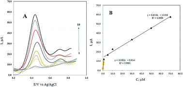
In this study, a Fe3O4@Pt nanoparticle and multi-walled carbon nanotube (MWCNT) modified carbon paste electrode was used as a fast and sensitive tool for the electrochemical determination of doxorubicin (DOX). The electrochemical oxidation of DOX was investigated at Fe3O4@Pt/MWCNT/CPE using the differential pulse voltammetry method. The developed electrode exhibited excellent electrochemical activity towards the electrochemical oxidation of the investigated anticancer drug. Under the optimized experimental conditions, a linear calibration curve in the range of 0.05 to 70.0 μmol L−1 with two different slopes and a detection limit of 1 nmol L−1 was obtained. Finally, the method was successfully employed for the voltammetric determination of DOX in a urine sample at trace levels with good recoveries.


Introduction

Doxorubicin (DOX) (Scheme 1) known as Adriamycin, is an anthracycline antibiotic and a drug used in cancer chemotherapy. It works by intercalating DNA and could cause some adverse effects such as life-threatening heart damage. Cardiomyopathies and myelo suppression are associated with the use of doxorubicin at high doses.1–3 Therefore, the development or improvement of analytical methods for monitoring its level in urine and serum samples is necessary. Several methods have been reported for the determination of doxorubicin based on liquid chromatography,4–8 capillary electrophoresis,9,10 room temperature phosphorescence spectra,11 UV-vis spectrophotometry,12 and fluorimetric methods.13 However, some of these methods suffer from some disadvantages such as the requirement for sample pretreatment, high costs, and long analysis time. Promising alternatives for this purpose are electroanalytical methods, which are able to offer high sensitivity, rapid response, easy operation, and low cost.
image file: c6ra13935c-s1.tif
Scheme 1 Chemical structure of doxorubicin.

By far, few producers based on the electrochemical oxidation or reduction of DOX using different electrodes have been reported. Fei et al. have used a glassy carbon electrode (GCE) modified with a nano-titania/Nafion composite film for voltammetric determination of trace DOX in human plasma samples.14 The modified GCE exhibited better electrochemical behavior toward the reduction of DOX compared to the bare GCE and enabled sensitive determination of the drug with 1.0 nM detection limit. In another study, Guo et al. have used a cyclodextrin–graphene hybrid nanosheets modified GCE for determination of DOX and methotrexate.15 In the case of DOX, the peak current increased 26.5 fold compared to the results obtained on the bare GCE. The result of this study showed that the prepared sensor provides a promising tool for the determination of trace amounts of DOX in biological, clinical and pharmaceutical fields with 0.1 nM detection limit. Toward electrochemical determination of DOX in human urine samples, Vajdle et al. have used a renewable silver-amalgam fill electrode for electrochemical reduction of DOX.16 Herein, an electrochemical method based on Fe3O4@Pt/MWCNT modified carbon paste electrode (CPE) is developed for the determination of DOX. CPE, which is made up of carbon particles and an organic liquid, is widely applied in the electroanalytical community due to its low cost, ease of fabrication, high sensitivity for detection, and renewable surface. Lately, to improve the sensitivity, selectivity, detection limit, and other features of CPE, different nanoparticles have been used as modifiers in the composition of CPE.

Recently monodisperse magnetic composite nanoparticles have gained extensive interest because of their unique potential applications in microelectronics,17 catalysis,18 photo catalysis,19 magnetic devices,20 chemisorption's,21 aerosols,22 and powder metallurgies.23 Among these nanocomposites, Fe3O4 magnetic nanocomposites, especially with core–shell structure, composed of bare Fe3O4 nanoparticles as core and some other materials as shell, have attracted increasing attention for their much better outstanding functionality. Furthermore, it was well known that bare Fe3O4 nanoparticles are easily aggregated and oxidized in air.24

To address the above-mentioned problems, several approaches, such as the formation of core–shell structure, have been demonstrated to protect the naked magnetic nanoparticles using polymers or inorganic materials (including noble metals and oxides).25–30 On the other hand, Pt nanoparticles have been considered as one of the best candidates for building novel magnetic nanocomposite owing to its high catalytic activity and chemical inertness.31 Incorporation of Pt and magnetic Fe3O4 core (Fe3O4@Pt) could combine the advantages of chemical stability and biocompatibility of Pt and the magnetic properties of Fe3O4.

Experimental

Chemicals

All the used chemicals were of analytical reagent grade and were purchased from Merck Company (Darmstadt, Germany). Doxorubicin hydrochloride was purchased from Sigma-Aldrich Company. Multi-walled carbon nanotubes (10–20 nm in diameter, the length of 30 μm and purity of 95%) were purchased from Neutrino Company (Iran). In all the measurements, the supporting electrolyte used was phosphate buffer solution of pH 8.0. High viscosity paraffin (d = 0.867 kg L−1) from Merck Company was used as the pasting liquid for the preparation of the carbon paste electrodes. All the solutions were prepared using double distilled water (DDW).

Apparatus

All electrochemical experiments including cyclic voltammetry (CV) and differential pulse voltammetry (DPV) were performed using a Metrohm Model 797-VA Computrace polarograph. A three-electrode system consisting of a modified CPE as the working electrode, a platinum wire as the counter electrode, and an Ag/AgCl (saturated KCl) as the reference electrode was used. pH of the solutions was adjusted by a Metrohm Model 713 pH lab (Herisau, Switzerland).

Size and morphological properties of the synthesized nanoparticles were investigated using a scanning electron microscope (MIRA FEG-SEM, TESCAN). The crystal structure of synthesized nanoparticles was determined by an X-ray diffractometer (XRD, 38066 Riva, d/G. Via M. Misone, 11/D (TN) Italy) at ambient temperature. The mid-infrared spectra of the synthesized nanoparticles in the region 4000–400 cm−1 were recorded by an FT-IR spectrometer (Perkin-Elmer model Spectrum GX) using KBr pellets.

Synthesis of Fe3O4@Pt nanoparticles

Synthesis of Fe3O4 nanoparticles (MNPs). Fe3O4 was synthesized by a solvothermal reduction method with minor modifications.32 Typically, FeCl3·6H2O (1.35 g) was dissolved in ethylene glycol (40.0 mL) to form a clear solution, followed by the addition of sodium acetate (3.6 g) and polyethylene glycol (1.0 g). The mixture was ultrasonicated vigorously for 30.0 min, refluxed at 180 °C for 8 h, and then allowed to cool down to room temperature. The black products were washed several times with ethanol and DDW water and then dried at 60 °C for 6 h.
Synthesis of silica-coated magnetite nanoparticles (SCMNPs). SCMNPs were prepared according to a previously reported method with minor modifications.33 Typically, 0.5 g of MNPs was dispersed in 60.0 mL ethanol and 10 mL DDW by sonication for 15 min, followed by the addition of 1.0 mL ammonium hydroxide (25%) and 2.0 mL tetraethoxysilane sequentially. The mixture was reacted for 24 h at room temperature under continuous stirring. The resultant product was collected using an external magnetic field and rinsed six times with ethanol and DDW consecutively. Finally, the obtained SCMNPs were dried under vacuum at 60 °C for 3 h.
Synthesis of 3-aminopropyl triethoxysilane (APTES) coated SCMNPs (APTES-SCMNPs). To modify the surface of the SCMNPs with amino groups, 0.3 g of the nanoparticles was added in to 70 mL ethanol flask followed by the addition of 0.5 mL of APTES under stirring. The mixture was reacted for 7 h at a mild temperature under continuous stirring. The resultant product was collected using an external magnetic field, and rinsed six times with ethanol and DDW consecutively.34 Finally, the obtained APTES-SCMNPs nanoparticles were dried under vacuum at 60 °C for 6 h.
Synthesis of Fe3O4@Pt nanoparticles. Fe3O4@Pt nanoparticles were prepared according to a previously reported method with minor modifications.35 Typically, 0.1 g of APTES-SCMNPs was dispersed in 5.0 mL DDW by sonication for 10 min, followed by the addition of 4.0 mL H2PtCl6 solution (0.02 mol L−1) under stirring. Then, 9.0 mL of hydrazine hydrate (N2H5OH) was dropped into the mixture solution until the mixture color changed from yellow to black. The resultant dark material was precipitated and separated using a magnet and washed six times with ethanol. Finally, the obtained Fe3O4@Pt nanoparticles were dried under vacuum at 70 °C for 6 h.

Preparation of working electrode

The MWCNT/Fe3O4@Pt nanoparticles paste mixture was prepared by hand-mixing of 12.5% (w/w) MWCNT powder, 12.5% (w/w) Fe3O4@Pt nanoparticles, 50% (w/w) graphite and 25% (w/w) paraffin. The MWCNT paste mixture was prepared by hand-mixing of 12.5% (w/w) MWCNT powder, 62.5% (w/w) graphite and 25% (w/w) paraffin. The Fe3O4@Pt nanoparticles paste mixture was prepared by hand-mixing of 12.5% (w/w) Fe3O4@Pt nanoparticles, 62.5% (w/w) graphite, and 25% (w/w) paraffin. The bare CPE was prepared by mixing 75/25% (w/w) ratio of graphite powder and paraffin. The paste was then packed into a plastic syringe tube with the inner diameter of 3 mm. Electrical contact was made by pushing a copper wire down the glass tube into the back of the mixture. When necessary, a new surface was obtained by pushing an excess of the paste out of the tube and polishing it on a weighing paper.

Real sample preparation

Drug-free human urine samples were collected from healthy donors with informed consent and all experiments were performed in compliance with the relevant laws and institutional guidelines. Behbood Institute (Hamedan, Iran) has approved the experiments. The urine sample was centrifuged for 10 min. Then, 1.0 mL of the sample was diluted with 20.0 mL of a phosphate buffer (pH = 8.0) solution, and directly subjected to DPV procedure. The urine sample was spiked with DOX at μmol L−1 concentration levels.

General procedure

The required volume of DOX standard solution was added to a 25 mL volumetric flask and diluted up to the volume with the phosphate buffer (pH 8.0). This solution was added to the electrochemical cell. After that, the modified electrode was placed into the test solution and then the CV or differential pulse voltammetry (DPV) were performed. DPV scanning was performed in the potential range of 0.00 to 0.80 V vs. Ag/AgCl at the scan rate of 142.8 mV s−1. DPV was performed in the same potential range with pulse amplitude of 90.0 mV, voltage step of 10.0 mV, pulse time of 0.007 s and voltage step time 0.07 s.

Results and discussion

Characterization of the Fe3O4@Pt nanoparticles

The FTIR spectrum of the products in each step of the APTES-SCMNPs synthesis was recorded to verify the formation of the expected products. The related spectra are shown in Fig. 1. The characteristic absorption band of Fe–O in Fe3O4 (around 540 cm−1) is observed in Fig. 1a. A strong peak at around 1090 cm−1 in Fig. 1b is attributed to Si–O in SiO2. The peaks at around 3400 cm−1 in Fig. 1c is attributed to N–H in NH2. Based on these results, it can be concluded that the fabrication procedure has been successfully performed. Fig. 2 shows the XRD pattern of Fe3O4@Pt nanoparticles. The peaks are indexed to the (220), (311), (400), (422), (511) and (440) reflection characteristics of the cubic spinel phase of Fe3O4 (JCPDS powder diffraction data file no. 86-1354), and diffraction peaks indexed to the (111) and (220) are reflection characteristics of the cubic spinel phase of Pt (JCPDS powder diffraction data file no. 86-2343). The average crystallite size of the Fe3O4@Pt nanoparticles was estimated as 6.95 nm from the XRD data according to the Scherer equation.36
image file: c6ra13935c-f1.tif
Fig. 1 FT-IR spectra for (a) MNPs, (b) SCMNPs and (c) APTES-SCMNPs.

image file: c6ra13935c-f2.tif
Fig. 2 XRD pattern for the Fe3O4@Pt nanoparticles.

To confirm the composition of the Fe3O4@Pt nanoparticles, X-ray energy dispersive spectroscopy (EDS) spectrum was obtained. The result is shown in Fig. 3. EDS indicated the presence of Fe, O, Si, and Pt. The EDS spectrum demonstrated the presence of both Fe and Pt elements in the modified composites, confirming that the surfaces of magnetite nanoparticles are successfully modified by platinum coating. For characterizing the surface morphology of Fe3O4@Pt nanoparticles, a scanning electron microscope (SEM) was employed. Fig. 4 shows the SEM image that Fe3O4@Pt nanoparticles were highly crystalline and homogenously distributed with an average size of 7.80–60.0 nm.


image file: c6ra13935c-f3.tif
Fig. 3 EDS analysis of the Fe3O4@Pt nanoparticles.

image file: c6ra13935c-f4.tif
Fig. 4 The SEM image of Fe3O4@Pt nanoparticles.

Point of zero charges (pHPZC) of Fe3O4@Pt nanoparticles

The pHPZC of the Fe3O4@Pt nanoparticles was determined in degassed 0.01 mol L−1 NaNO3 solution at room temperature. Aliquots of 30.0 mL 0.01 mol L−1 NaNO3 were mixed with 0.02 g of the nanoparticles in several beakers. The initial pH of the solutions was adjusted to 3.0, 4.0, 5.0, 6.0, 7.0, 8.0 and 9.0 using 0.01 mol L−1 of HNO3 and/or NaOH solutions, as appropriate. The initial pH values of the solutions were recorded, and the beakers were covered with parafilm and shaken for 24 h. The final pH values were recorded, and the differences between the initial and final pH (ΔpH) of the solutions were plotted against their initial pH values. The pHPZC corresponds to the pH where ΔpH = 0.13 The pHPZC for Fe3O4@Pt nanoparticles was determined using the above procedure and a value of 7.0 was obtained. The results are shown in Fig. 5.
image file: c6ra13935c-f5.tif
Fig. 5 Point of zero charge (pHPZC) of the Fe3O4@Pt nanoparticles.

Electrochemical behaviors of DOX at different electrodes surface

To elucidate the electrode reaction of DOX, DPV technique was used. The DPVs recorded in 0.1 mol L−1 phosphate buffer with pH 8.0 as supporting electrolyte in the presence of 50.0 μmol L−1 of DOX at bare CPE, Fe3O4/CPE, Fe3O4@Pt/CPE, MWCNT/CPE, and Fe3O4@Pt/MWCNT/CPE are shown in Fig. 6. Fig. 6 shows a well-defined oxidation peak at 0.370 V was observed for DOX at Fe3O4@Pt/MWCNT/CPE with a current of 54.3 μA. The peak currents of DOX are approximately 18 μA, 20 μA and 39 μA for CPE, Fe3O4@Pt/CPE, and MWCNT/CPE, respectively. The anodic current obtained at Fe3O4@Pt/MWCNT/CPE for the oxidation of DOX was observed to be significantly higher than those obtained with CPE, Fe3O4@Pt/CPE, and MWCNT/CPE. These show that the high electrocatalytic activity of Fe3O4@Pt/MWCNT/CPE could be ascribed to the presence of MWCNT and Fe3O4@Pt nanoparticles, which enhanced the conductivity, surface area, and facilitated the electron transfer between the DOX and the electrode surface. The nanocomposite structure formed by the combination of Fe3O4@Pt nanoparticles and MWCNT with an excellent conductivity, coupled with this effect and increased the activity and sensitivity of the newly prepared modified electrode (Fe3O4@Pt/MWCNT/CPE) towards the DOX.
image file: c6ra13935c-f6.tif
Fig. 6 Differential pulse voltammograms of DOX in 50.0 μmol L−1 solution of DOX by (a) CPE, (b) Fe3O4/CPE, (c) Fe3O4@Pt/CPE, (d) MWCNT/CPE, and (e) Fe3O4@Pt/MWCNT/CPE.

Influence of pH

As the protons take part in the electrochemical oxidation of DOX, the peak current and peak potential are affected by pH of the working solution. Therefore, the current responses and oxidation potentials of DOX at Fe3O4@Pt/MWCNT/CPE were investigated in the pH range from 4.0 to 9.0 of phosphate buffer solution by DPV. As shown in Fig. 7A, by increasing pH, the oxidation potential for DOX became more negative. By changing pH from 4.0 to 9.0, the oxidation potential of DOX was shifted from 0.62 to 0.32 V. The relationship between the potential and pH were linear, and the regression equation was as follow: Epa (V) = 0.8599 − 0.0601pH (R2 = 0.9892). The slope of the equation is very close to the anticipated Nernstian value of −59 mV for electrochemical process involving the same number of protons and electrons. As shown in Fig. 7B, by increasing the pH, the oxidation peak currents of DOX increased and the maximum oxidation peak current for DOX was observed at pH 8.0. In the case of DOX, the only species significantly present in the region between Hammett acidity −4.0 and pH 8.0 is the singly charged species with a positive charge at the amino sugar group.13 However, at a pH higher than 8.0, this monocation can lose a proton either from a phenolic group to form a zwitterion or from the amino sugar group to form the neutral species. The generated species may then lose a proton to form the singly charged anions. On the other hand, at pH range of 7.0–8.0, the Fe3O4@Pt nanoparticles surface charge is negative regarding the pHPZC, and the electrostatic attraction forces between the positively charged drug molecules and the negatively charged nanoparticles are responsible for the higher electrochemical signals. At higher pH (i.e. >8.0), electrostatic repulsion between the negatively charged drug molecules and the nanoparticles are responsible for the lower electrochemical signals. It should be noted that at pH > 8.0, the drug is partially in its neutral form, and this is another reason for a decrease in the signals due to a lack of electrostatic attraction forces. Therefore, this value was selected for further the experiments.
image file: c6ra13935c-f7.tif
Fig. 7 (A) DPVs obtained at the Fe3O4@Pt/MWCNT/CPE in phosphate buffer solution in different pH containing 50.0 μmol L−1 DOX, (B) influence of pH values on the current response of DOX at the Fe3O4@Pt/MWCNT/CPE.

Effect of scan rate on the oxidation of DOX at Fe3O4@Pt/MWCNT/CPE

The effect of scan rate on the response of 50.0 μmol L−1 DOX was also investigated by CV in the potential range from 0.01 to 0.5 V. From Fig. 8A, it can be observed that the oxidation peak potential shifts positively with the increase of scan rate. As shown in Fig. 8B, the oxidation peak currents Ipa of DOX increases linearly with the square root of scan rate. The regression equation of DOX was Ipa (μA) = 29.056ν0.5 − 2.4085 (R2 = 0.9915). The results demonstrate that the electrochemical process is a typical diffusion-controlled process.
image file: c6ra13935c-f8.tif
Fig. 8 (A) CVs of 50.0 μmol L−1 DOX on the Fe3O4@Pt/MWCNT/CPE at different scan rates (0.01 V s−1 to 0.5 V s−1) in phosphate buffer solution (pH 8.0) (B) the plots of the peak current versus square root of scan rate.

Analytical performance characteristics

The important electrochemical parameters, which affect the DPVs, including pulse amplitude, pulse time, voltage step, voltage step time, deposition time and potential were studied. The results of are shown in Table 1. Fig. 9A presented DPV curves of different concentrations of DOX at Fe3O4@Pt/MWCNT/CPE under the optimum conditions. Under the optimized experimental conditions in the range of 0.05 to 70.0 μmol L−1, a linear calibration curve was obtained with two different slopes. The linear regression equation was Ipa1 = 0.9344 + 10.982C (R2 = 0.9993) and Ipa2 = 13.818 + 0.6319C (R2 = 0.9909), where Ipa was the anodic peak current (μA) and C was the DOX concentration (μmol L−1). The limits of detection (LOD) and quantitation (LOQ) were calculated using the relation kSb/m, where k = 3 for LOD and 10 for LOQ, where Sb representing the standard deviation of the peak currents of the blank (n = 5) and m representing the slope of the calibration curve for DOX. The LOD and LOQ values for the determination of DOX were 1.0 and 33.0 nmol L−1, respectively. The dependence of peak current versus the concentration of DOX was shown in Fig. 9B.
Table 1 Optimum values of the instrumental parameters
Parameters Optimized values
Pulse amplitude (V) 0.09
Pulse time (s) 0.007
Voltage step (V) 0.01
Voltage step time (s) 0.07
Deposition potential (V) 0.30
Deposition time (s) 20.0


image file: c6ra13935c-f9.tif
Fig. 9 (A) DPVs for 0.05 (1), 0.10 (2), 0.50 (3), 0.70 (4), 1.0 (5), 5.0 (6), 10.0 (7), 30.0 (8), 50.0 (9) and 70.0 (10) μmol L−1 DOX at Fe3O4@Pt/MWCNT/CPE in phosphate buffer (PH 8.0), (B) the plots of the peak current as a function of DOX concentration in the range of 0.05–70.0 μmol L−1.

Repeatability, reproducibility, and stability

The repeatability of Fe3O4@Pt/MWCNT/CPE toward DOX detection was also investigated, and the standard deviation in the oxidation current was about 2.9% for six successive measurements at 50.0 μmol L−1 solution of DOX. In addition, the reproducibility of Fe3O4@Pt/CNT/CPE toward DOX detection was also investigated, and the standard deviation in the oxidation current was about 3.8% for four successive measurements at 50.0 μmol L−1 solution of DOX.

Moreover, the stability of the modified electrode was studied during its storage in air at room temperature. Fe3O4@Pt/MWCNT/CPE has reserved 95% of its initial activity for more than 30 days. These results indicate that the modified electrode has high reproducibility and stability.

Interference effect

The influence of various potentially interfering substances with the determination of DOX was studied under the optimum conditions. Possible interference was investigated by adding various ions and biological compounds to phosphate buffer (pH 8.0) in the presence of 1.0 μmol L−1 DOX. The tolerance limit for each interferer was regarded as the maximum concentration which gives a relative error of less than ±5.0%. The common ions such as Na+, K+, Ca2+, Mg2+, CO32−, SO42−, NO2 and Cl did not show interference with DOX detection. As for the common interference in biological samples for the determination of DOX, different concentration of glucose, urea and lactose monohydrate had no effective interference with the current response of DOX. The results are given in Table 2, suggesting that this proposed method has excellent selectivity toward determination of DOX in pharmaceutical and biological samples.
Table 2 Interference of some foreign substances for 1.0 μmol L−1 DOX
Interferes Tolerance level (μmol L−1)
Na+, Cl, K+, NO2, Mg2+, SO42−, CO32− 1000
Glucose, urea, lactose monohydrate 200
Ca2+ 100


Real sample analyses

The proposed sensor was further tested for its practical performance concerning DOX detection in a real sample of urine. Recovery tests were performed by spiking the standard DOX solution in (172.0 μmol L−1) to the diluted real samples. The DOX recovery in the spiked urine sample was in the range of 99–101% which demonstrates that the method is appropriate for analyzing DOX in the triplicate analysis. The summarized results of the analysis are given in Table 3.
Table 3 Determination of DOX in the urine sample (n = 4)
Sample Added (μmol L−1) Found (μmol L−1) Recovery%
Urine ND
1 1.011 ± 0.04 101.1
50 49.8 ± 1.58 99.6


Conclusions

This paper, for the first time, investigated the electro-oxidation behavior of DOX on the Fe3O4@Pt/MWCNT/CPE. The DPV method developed in this study was sensitive, selective, accurate, precise and easy to use for the determination of DOX in human urine. The sensor has great capability in catalyzing the oxidation of DOX and can be used as an electrochemical sensor for the determination of DOX. Incorporation of Fe3O4@Pt nanoparticles and MWCNT improved the electrocatalytic property of modified electrode towards DOX. The calibration curve was obtained by DPV in a linear range of 0.05–70.0 μmol L−1 of DOX with a limit detection of 1.0 nmol L−1. The simple preparation procedure of the modified electrodes, a wide linear concentration range of the DOX, low detection limit, good reproducibility, and high stability of the method for the investigated drug determination suggest that the method is a good candidates for practical applications.

Acknowledgements

This work was financially supported by the Bu-Ali Sina University Research Council and the Center of Excellence in Development of Environmentally Friendly Methods for Chemical Synthesis (CEDEFMCS).

Notes and references

  1. V. T. De Vita, S. A. Rosenberg and S. Hellman, Cancer principles and practice of oncology, Lippincott, Williams & Wilkins, Philadelphia, 2001 Search PubMed.
  2. C. H. Takimoto, V. T. DaVita, S. Hellman and S. A. Rosenberg, Cancer: principles & practice of oncology, Lippincott, Williams & Wilkins, Philadelphia, 7th edn, 2005 Search PubMed.
  3. G. Gregoriadis, Liposomes as Drug Carriers: Recent Trends and Progress, John Wiley and Sons, New York, 1988 Search PubMed.
  4. C. Sottani, G. Poggi, F. Melchiorre, B. Montagna and C. Minoiaa, J. Chromatogr. B: Anal. Technol. Biomed. Life Sci., 2013, 915, 71–78 CrossRef PubMed.
  5. C. Mazuel, J. Grove, G. Gerin and K. P. Keenan, J. Pharm. Biomed. Anal., 2003, 33, 1093–1102 CrossRef CAS PubMed.
  6. S. Ahmed, N. Kishikawa, K. Ohyama, M. Wada, K. Nakashima and N. Kuroda, Talanta, 2009, 78, 94–100 CrossRef CAS PubMed.
  7. E. Sakai-Kato, K. Saito, K. Ishikura and T. Kawanishi, J. Chromatogr. B: Anal. Technol. Biomed. Life Sci., 2010, 878, 1466–1470 CrossRef PubMed.
  8. Q. Zhou and B. Chowbay, J. Pharm. Biomed. Anal., 2002, 30, 1063–1074 CrossRef CAS PubMed.
  9. T. Perez-Ruiz, C. Martinez-Lozano, A. Sanz and E. Bravo, Electrophoresis, 2001, 22, 134–138 CrossRef CAS PubMed.
  10. G. Whitaker, A. Lillquist, S. A. Pasas, R. O'Connor, F. Regan, C. E. Lunte and M. R. Smyth, Sep. Sci., 2008, 31, 1828–1833 CrossRef CAS PubMed.
  11. F. Alava-Moreno, M. J. Valencia-González and M. E. Díaz-García, Analyst, 1998, 123, 691–694 RSC.
  12. B. L. Long, Y. Z. Hai and M. X. Xian, J. Mol. Struct., 2005, 749, 108–113 CrossRef.
  13. M. Ahmadi, T. Madrakian and A. Afkhami, New J. Chem., 2015, 39, 163–171 RSC.
  14. J. Fei, X. Wen, Y. Zhang, L. Yi, X. Chen and H. Cao, Microchim. Acta, 2009, 164, 85–91 CrossRef CAS.
  15. Y. Guo, Y. Chen, Q. Zhao, S. Shuang and C. Dong, Electroanalysis, 2011, 23, 2400–2407 CrossRef CAS.
  16. O. Vajdle, J. Zbiljić, B. Tasić, D. Jović, V. Guzsvány and A. Djordjevic, Electrochim. Acta, 2014, 132, 49–57 CrossRef CAS.
  17. R. P. Andres, j. D. Bielefeld, J. I. Henderson, D. B. Janes, V. R. Kolagunta, C. P. Kubiak, W. J. Mahoney and R. G. Soifchin, Science, 1996, 273, 1690–1693 CrossRef CAS.
  18. H. Hirai, H. waka bayashi and M. komiyama, Chem. Lett., 1983, 12, 1047–1050 CrossRef.
  19. R. S. Sonawane, B. B. Kaleand and M. K. Dongare, Mater. Chem. Phys., 2004, 85, 52–57 CrossRef CAS.
  20. J. S. cheng, Y. Wu, Z. H. Xu, B. Hu, J. M. Bai, J. P. wang and J. shen, Appl. Phys. Lett., 2007, 90, 23–28 Search PubMed.
  21. T. philippe, D. Robert, C. Bernard, C. Christophe, R. Severine and L. Lamy, Appl. Catal., B, 2009, 93, 280–284 Search PubMed.
  22. V. Tiwari, J. Jiang and V. Sethi, Appl. Catal., A, 2008, 345, 241–246 CrossRef CAS.
  23. J. A. A. J. Perenboom, P. Wyderand and F. Meier, Phys. Rep., 1981, 78, 173–292 CrossRef CAS.
  24. H. Zeng, J. Li, J.-P. Liu, Z.-L. Wang and S. H. Sun, Nature, 2002, 420, 395–398 CrossRef CAS PubMed.
  25. Y. Cai, J. S. Jiang, B. Zheng and M. R. Xie, J. Appl. Polym. Sci., 2013, 127, 49–56 CrossRef CAS.
  26. Y. Chunmei, G. Lili, Z. Xiaohui, B. Ning and G. Haiying, Electrochim. Acta, 2011, 56, 9056–9063 CrossRef.
  27. Y. Chunmei, Z. Xiaohui and H. Gu, Electrochim. Acta, 2010, 55, 8738–8743 CrossRef.
  28. C. Yu, J. Guo and H. Gu, Microchim. Acta, 2009, 166, 215–220 CrossRef CAS.
  29. Y. Chunmei, G. Jianwei and G. Haiying, Electroanalysis, 2010, 22, 1005–1011 CrossRef.
  30. H. Fan, Z. Q. Pan and H. Y. Gu, Microchim. Acta, 2010, 168, 239–244 CrossRef CAS.
  31. C. Wang, H. Daimon and S. Sun, Nano Lett., 2009, 9, 1493–1496 CrossRef CAS PubMed.
  32. H. Deng, X. Li, Q. Peng, X. Wang, J. Chen and Y. Li, Angew. Chem., Int. Ed., 2005, 44, 2782–2785 CrossRef CAS PubMed.
  33. A. M. El-Toni, M. A. Ibrahim, J. P. Labis, A. Khan and M. Alhoshan, Int. J. Mol. Sci., 2013, 14, 11496–11509 CrossRef PubMed.
  34. E. Haghshenas, T. Madrakian and A. Afkhami, Mater. Sci. Eng., C, 2015, 57, 205–214 CrossRef CAS PubMed.
  35. Q. He, Z. W. L. Zeng and C. Huang, J. Sens. Mater., 2012, 24, 233–244 CAS.
  36. A. Afkhami, H. Ghaedi, T. Madrakian, M. Ahmadi and H. Mahmood-Kashani, Biosens. Bioelectron., 2013, 44, 34–40 CrossRef CAS PubMed.

This journal is © The Royal Society of Chemistry 2016
Click here to see how this site uses Cookies. View our privacy policy here.