
Ultrathin anatase nanosheets with high energy facets exposed and related photocatalytic performances†
Yongzheng Wanga,
Jing Yea,
Yu Shena,
Mingjiang Xiea,
Shuangshuang Yangb,
Chao Liua,
Xiangke Guoa,
Luming Penga,
Weiping Ding *a and
Xuefeng Guo*a
*a and
Xuefeng Guo*a
aKey Laboratory of Mesoscopic Chemistry of MOE, School of Chemistry and Chemical Engineering, Nanjing University, Nanjing 210093, China. E-mail: guoxf@nju.edu.cn; dingwp@nju.edu.cn
bSchool of Chemistry and Chemical Engineering, Southeast University, Nanjing 211189, China
First published on 24th June 2016
Abstract
Anatase-type titania with ultrathin nanosheet morphology and sintering-resistant structure was constructed from monolayer titanate nanosheets isolated by uniform silica nanoparticles. The obtained anatase titania nanosheets possess high accessible surface area, ultrathin thickness (∼0.6 nm), dominant (116) facets exposed, wide bandgap and exhibits excellent photocatalytic activity.
Owing to the unique features of exotic electronic structures and high surface areas arising from the ultrathin thickness of one or several atoms, two dimensional (2D) nanomaterials have great potential applications in energy storage,1,2 catalysis,3,4 sensing,5,6 environmental technologies,7,8 and so on. Among the 2D nanomaterials, inorganic nanosheets have attracted increasing attention due to their diversity in chemical composition, crystal structure, physicochemical property, etc.9,10 However, the property and practical application of these inorganic nanosheets have remained much less explored, primarily due to the difficulty in synthesizing well-defined inorganic nanosheets in large quantities.11
Titania (TiO2), one of the most important inorganic materials, has long been widely studied on catalysis (especially photocatalysis),12–15 sensing,16 energy storage and conversion.17–19 It is reported that the crystalline phase (anatase or rutile)20–23 and crystal facets24,25 are the key factors influencing the performances of titania. As we known, anatase TiO2 usually shows much higher activities than that of rutile TiO2.26–28 On the other hand, crystal facets were reported as another key factor affecting the intrinsic reactivities of anatase, especially photocatalysis activity. For example, high-energy facets {001} and {110} show higher photocatalytic activity than low-energy facets {101}.29,30 High-index facets, such as facets {116}, also possess high activity for their high surface energy.31–33 Nevertheless, high-index facets are hardly exposed in anatase crystals prepared by conventional methods because of their energy-instability. Usually, the exposed high-energy facets were obtained by controlled growth of special geometry-shaped anatase crystals, such as cutting octahedron shape with top face of (001) facets.29 However, due to the geometric integrity, these high energy facets always exist accompanied by considerable percentage of side facets (usually are low energy facets). Theoretically, ideal 2D single crystal nanosheet with thickness of one atom could exhibit onefold facet paralleled to the surface without side facets. Accordingly, much effort has been made to prepare such 2D anatase nanosheet. Generally, ultrathin titanate nanosheet can be easily prepared by liquid exfoliation method,34 but the thickness would be greatly increased during phase transformation from titanate to anatase due to the inevitable restacking/sintering of the titanate nanosheets.9,35 The currently reported anatase nanosheets usually have large thickness,36,37 thus the side facets could not be ignored. Up to date, constructing sintering-resistant ultrathin anatase TiO2 nanosheets with onefold facets exposed still remains a challenge.
Herein, as illustrated in Fig. 1, we reported a facile method to obtain ultrathin 2D anatase nanosheets by isolating the monolayer titanate nanosheets (TiONS) with monodispersed uniform silica nanoparticles. Firstly, the as-made silica sol and the exfoliated titanate were mixed to undergo a co-assembly via electrostatic and hydrogen bond interactions. Then, the obtained mixture was dried by a one-pot freeze-drying method and the obtained silica isolated titanate nanosheets were denoted as TS-X (T: titania; S: silica; X: sample number associated with different mass ratio of T/S). After freeze-drying, the obtained composite was transformed to the target structure by calcination and the final anatase nanosheets were denoted as TS-X-C.
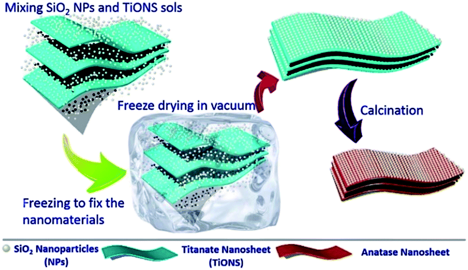 | ||
| Fig. 1 Schematic diagram towards the fabrication of silica nanoparticles isolated ultrathin anatase TiO2 nanosheets. | ||
Fig. S1a (in ESI†) shows the nanosheet-like morphology of the exfoliated titanate (TiONS). The thickness of TiONS confirmed by atomic force microscope (AFM in Fig. S1b and c†) is about 1.0 nm. Monodispersed silica nanoparticles with the uniform size of ∼14 nm (Fig. S2, ESI†) were used to isolate the obtained TiONS as depicted in Fig. 1. Typically, when the mass ratio of titania/silica in the final TS-X reaches 1![[thin space (1/6-em)]](https://www.rsc.org/images/entities/char_2009.gif) :2.5 (TS-5), the TiONS could be effectively isolated and thus well-defined ultrathin titania nanosheets (TS-5-C) were obtained after calcination. As Fig. 2a shown, after calcination at 773 K, the obtained TS-5-C possesses a porous nanosheet morphology composed of ultrathin titania nanosheets and attached silica nanoparticles. The magnified TEM image in Fig. 2b and the high-resolution TEM images (HRTEM) in Fig. 2c and d further confirm the existence of the ultrathin anatase nanosheet. Judged from the HRTEM image (Fig. 2d), the thickness of the anatase nanosheet in TS-5-C is about 0.5–0.6 nm, which is close to the thickness of the exfoliated titanate nanosheet (TiONS), indicating that the TS-5-C possesses a sintering-resistant structure due to the isolation of uniform silica nanoparticles. The crystallinity of TS-5-C was confirmed by HRTEM analysis. The HRTEM image of TS-5-C (Fig. 2e) displays the visible lattice fringes with d-spacings of 0.358 nm corresponding to the {101} and {011} planes of anatase TiO2. The included angle of the fringes is determined to be 97.8°, identifying the two equivalent planes of {101} and {011} standing vertically as the side faces with an angle of 97.8° and the {116} planes laying horizontally as the top face.32,33 The corresponding FFT pattern (inset in Fig. 2e) obtained on this image area can be indexed into diffraction spots of the [11−1] zone, which also verify the {116} facets paralleled to the top surface. As simulated in Fig. 2f, it can be deduced from the HRTEM image that the crystal facets of ultrathin titania nanosheets in TS-5-C exposed side face of {101} planes and top face of {116} planes. The above characterizations indicate that the developed strategy realizes the construction of ultrathin titania nanosheet with exposed high-energy facets. The successful construction of the ultrathin titania nanosheet can be attributed to the effective isolation of titanate nanosheet by silica nanoparticles. As the SEM images shown in Fig. S3a and b,† the surface of TS-5 is rougher than that of TiONS because the surface of TiONS adsorbs many silica nanoparticles. The TEM images in Fig. S3c and d† further confirm that the TiONS could be isolated by the adsorbed silica nanoparticles instead of restacking with each other.
:2.5 (TS-5), the TiONS could be effectively isolated and thus well-defined ultrathin titania nanosheets (TS-5-C) were obtained after calcination. As Fig. 2a shown, after calcination at 773 K, the obtained TS-5-C possesses a porous nanosheet morphology composed of ultrathin titania nanosheets and attached silica nanoparticles. The magnified TEM image in Fig. 2b and the high-resolution TEM images (HRTEM) in Fig. 2c and d further confirm the existence of the ultrathin anatase nanosheet. Judged from the HRTEM image (Fig. 2d), the thickness of the anatase nanosheet in TS-5-C is about 0.5–0.6 nm, which is close to the thickness of the exfoliated titanate nanosheet (TiONS), indicating that the TS-5-C possesses a sintering-resistant structure due to the isolation of uniform silica nanoparticles. The crystallinity of TS-5-C was confirmed by HRTEM analysis. The HRTEM image of TS-5-C (Fig. 2e) displays the visible lattice fringes with d-spacings of 0.358 nm corresponding to the {101} and {011} planes of anatase TiO2. The included angle of the fringes is determined to be 97.8°, identifying the two equivalent planes of {101} and {011} standing vertically as the side faces with an angle of 97.8° and the {116} planes laying horizontally as the top face.32,33 The corresponding FFT pattern (inset in Fig. 2e) obtained on this image area can be indexed into diffraction spots of the [11−1] zone, which also verify the {116} facets paralleled to the top surface. As simulated in Fig. 2f, it can be deduced from the HRTEM image that the crystal facets of ultrathin titania nanosheets in TS-5-C exposed side face of {101} planes and top face of {116} planes. The above characterizations indicate that the developed strategy realizes the construction of ultrathin titania nanosheet with exposed high-energy facets. The successful construction of the ultrathin titania nanosheet can be attributed to the effective isolation of titanate nanosheet by silica nanoparticles. As the SEM images shown in Fig. S3a and b,† the surface of TS-5 is rougher than that of TiONS because the surface of TiONS adsorbs many silica nanoparticles. The TEM images in Fig. S3c and d† further confirm that the TiONS could be isolated by the adsorbed silica nanoparticles instead of restacking with each other.
 | ||
| Fig. 2 (a) TEM image of TS-5-C; (b–e) HRTEM images and the corresponding FFT image (the insert in (e)) of TS-5-C; (f) the crystal structure diagram along anatase (11−6) planes in accordance to the image (e). | ||
To investigate the effect of the silica content on the final structure, the TS-Xs with different T/S mass ratio of 10:1 (TS-1), 5:1 (TS-2), 2.5:1 (TS-3), 1:1 (TS-4), 1:2.5 (TS-5), 1:5 (TS-6) were fabricated respectively. As the TEM images (Fig. S4†) shown, for the TS-Xs with the mass ratio of T/S exceeding 1:2.5, the TiONS can not be effectively separated. Only when the mass ratio of T/S reaches 1:2.5, the TiONS can be effectively isolated. Further increasing the amount of silica to T/S = 1:5 results in multilayer adsorbed silica nanoparticles on the titanate nanosheets (Fig. S4f,† TS-6). The TEM images of TS-Xs (X = 1–6) revealed that the critical value of T/S towards the efficient isolation of the exfoliated titanate is 1:2.5. The effect of the silica content on the final structure was further investigated by X-ray diffractions of the obtained TS-Xs shown in Fig. S5.† The XRD pattern of dried TiONS (Fig. S5a†) exhibits a typical diffraction peak of layered titanate around 8.5°, indicative of a restacked structure of the exfoliated nanosheets. As Fig. S5b† shown, the typical diffraction peak of TS-1 turns weaker, which can be ascribed to the isolation effect of silica nanoparticles. With the increase of silica content in the original assembly system, the intensity of the typical diffraction peak of TS-Xs gradually decreases. When the T/S mass ratio reaches to 1:2.5 and 1:5, no (0k0) peak of layered titanate can be observed in the XRD patterns of TS-5 and TS-6, suggesting an efficient separation of TiONS. In accord with the TEM results in Fig. S4,† the XRD patterns of TS-Xs further confirm that the critical value of the T/S mass ratio upon the efficient isolation of the exfoliated TiONS is 1:2.5.
N2 sorption analysis on the samples of TS-Xs-C were carried out to further characterize the specific surface area (SSA) and porosity. As the Fig. S6† shown, all the nitrogen sorption isotherms exhibit an IV type isotherms with a condensation step and a hysteresis loops at relative pressure of 0.4–0.6, indicative of the existence of porous structure. The existence of porous structure in the final samples was further confirmed by their pore size distribution curves in Fig. S7,† which also indicate that the TiONS were isolated by silica nanoparticles. The effect of silica content on the surface area of the TS-Xs-C was displayed in Fig. 3. It can be seen that the TS-5-C achieved a maximum surface area (318 m2 g−1) and the surface area decreases when the T/S below to the critical value of 1:2.5, suggesting the increase of silica content in the original assembly system is not always favourable to achieve larger specific surface area through the isolation. The detailed textual parameters derived from the nitrogen sorption measurements are listed in Table S2.† The calcined TiONS shows a very low SSA of 35 m2 g−1 due to the sintering of the nanosheets upon the calcination. With the increase of silica content, the SSA of the TS-Xs-C increases gradually from 35 m2 g−1 to 318 m2 g−1 (TS-5-C) due to the TiONS were gradually separated from each other by silica nanoparticles. Further increase of the silica content leads to a decrease of SSA to 284 m2 g−1.
 | ||
| Fig. 3 The nitrogen sorption isotherms of calcined TiONS and TS-5-C (left); the plot of SSA vs. T/S mass ratio of TS-Xs-C. | ||
Owing to the unique features of ultrathin nanosheet structure, large accessible surface and the exposed high energy facets, the obtained titania nanosheet may have potential applications in many fields. The photocatalytic performances of the TS-5-C, anatase nanoparticles (commercial ∼16 nm anatase TiO2 particles with specific surface area of 100 m2 g−1, Aladdin) and commercial P25 (Degussa) were examined under UV light irradiation towards the degradation of rhodamine B (RhB). As shown in Fig. 4a, the RhB can be degraded without the aid of catalyst, but the degradation efficiency is very low. Obviously, with the aid of photoresponsive catalyst, the degradation efficiency is greatly enhanced, in which the TS-5-C shows the highest photodegradation activity compared with anatase nanoparticles and commercial P25. After irradiation for 50 minutes, the degradation efficiency of RhB for TS-5-C is almost 100%, whereas degradation efficiency for anatase nanoparticles and P25 the anatase nanoparticles are of 76.1% and 92.9%, respectively. The superior photocatalytic performance of the obtained TS-5-C can be attributed to its ultrathin 2D structure, large accessible surface as well as the exposed high energy surface (116). The ultrathin 2D structure can reduce effectively the recombination of excited electron–hole pairs in body, thus leading more separated electron–hole pairs to participate the reaction. Meanwhile, the quantum effect originated from the ultrathin structure would lead to a variation of electronic structure of titania, thus affecting the photocatalytic performances. The UV-Vis diffuse reflectance (DR) spectra of TS-5-C and anatase nanoparticles were measured to investigate the differences of their electronic structure. As shown in Fig. 4b, both of the samples have sharp absorption peaks in UV region. The bandgap energies (Eg) of the samples derived from the Kubelka–Munk transformation are 3.61 eV (TS-5-C) and 3.26 eV (anatase nanoparticles), respectively. Compared to anatase nanoparticles, the larger Eg value of TS-5-C could be attributed to the quantum confinement effect of the ultrathin nanostructure,38 which indicates that the photogenerated hole in TS-5-C may have stronger oxidation power than that in anatase nanoparticles. The large accessible surface of TS-5-C enables more excited electron–hole pairs and more adsorbed reactants, benefiting the acceleration of the photodegradation reaction. The exposed (116) high energy planes can activate the adsorbed reactant more powerfully to be more active in catalytic reactions,33 which also contributes to the excellent photodegradation performance of TS-5-C. It's worth noting that the inactive silica nanoparticles in sample TS-5-C hamper the photodegradation activity of the anatase nanosheets because they occupy a large part of nanosheet surface. However, the silica nanoparticles are essential to obtain the stable anatase nanosheets with (116) high energy planes. So such unique anatase nanosheets with (116) high energy planes exposed may have a much higher photodegradation activity upon removing the silica nanoparticles. Based on the results, the possible mechanism for the photodegradation of RhB over TS-5-C is schematically shown in Fig. 5.39,40 Upon UV light irradiation, ultrathin anatase nanosheet in TS-5-C can be excited to generate electron–hole pairs, which locate on CB and VB respectively. The electron reacts with dissolved oxygen to generate O2˙−, and O2˙− then evolve into ˙OH.40 Meanwhile, the generated holes can react with OH− groups or H2O molecules to produce ˙OH. The formed ˙OH radicals are able to oxidize/degrade RhB to oxidation products.
 | ||
| Fig. 4 (a) Photocatalytic performances of anatase nanoparticles, P25 and TS-5-C towards photodegradation of RhB under UV light irradiation; (b) diffuse reflection UV-visible spectra and Tauc plots of TS-5-C and anatase nanoparticles using Kubelka–Munk transformation (insert). | ||
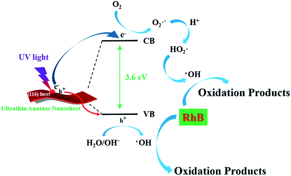 | ||
| Fig. 5 Schematic diagram of the ultrathin anatase nanosheet catalyst for the photodegradation of RhB. | ||
In conclusion, an ultrathin anatase nanosheet was fabricated via isolating the exfoliated titanate nanosheet with silica nanoparticles. The obtained anatase titania nanosheet possesses high accessible surface area, ultrathin thickness (∼0.6 nm), dominant (116) facets exposed, wide bandgap and exhibits superior photocatalytic activity to commercial P25. The presented methodology may be extended to the construction of many other metal oxides nanostructures.
Acknowledgements
This work was financially supported by the National Basic Research Program (2009CB623504), the National Science Foundation of China (21173119, 21273109, 21303083), the Natural Science Foundation of Jiangsu Province (BK20130563), the Specialized Research Fund for the Doctoral Program of Higher Education (20130091120045) and the Fundamental Research Funds for the Central Universities.Notes and references
- Y. Sun, Q. Wu and G. Shi, Energy Environ. Sci., 2011, 4, 1113 Search PubMed.
- M. D. Stoller, S. Park, Y. Zhu, J. An and R. S. Ruoff, Nano Lett., 2008, 8, 3498–3502 CrossRef CAS PubMed.
- A. R. Teixeira, X. Qi, W. C. Conner, T. J. Mountziaris, W. Fan and P. J. Dauenhauer, Chem. Mater., 2015, 27, 4650–4660 CrossRef CAS.
- Y. Sun, S. Gao, F. Lei and Y. Xie, Chem. Soc. Rev., 2015, 44, 623–636 RSC.
- Y. Fang, S. Guo, C. Zhu, Y. Zhai and E. Wang, Langmuir, 2010, 26, 11277–11282 CrossRef CAS PubMed.
- S. Wu, Q. He, C. Tan, Y. Wang and H. Zhang, Small, 2013, 9, 1160–1172 CrossRef CAS PubMed.
- W.-S. Wang, D.-H. Wang, W.-G. Qu, L.-Q. Lu and A.-W. Xu, J. Phys. Chem. C, 2012, 116, 19893–19901 CrossRef CAS.
- M. R. Allen, A. Thibert, E. M. Sabio, N. D. Browning, D. S. Larsen and F. E. Osterloh, Chem. Mater., 2010, 22, 1220–1228 CrossRef CAS.
- J. L. Gunjakar, I. Y. Kim, J. M. Lee, Y. K. Jo and S. J. Hwang, J. Phys. Chem. C, 2014, 118, 3847–3863 CrossRef CAS.
- S. Z. Butler, S. M. Hollen, L. Cao, Y. Cui, J. A. Gupta, H. R. Gutierrez, T. F. Heinz, S. S. Hong, J. Huang and A. F. Ismach, et al., ACS Nano, 2013, 7, 2898–2926 CrossRef CAS PubMed.
- M. Osada and T. Sasaki, Adv. Mater., 2012, 24, 210–228 CrossRef CAS PubMed.
- A. Fujishima and K. Honda, Nature, 1972, 238, 37–38 CrossRef CAS PubMed.
- G. Zhang, C. Ni, X. Huang, A. Welgamage, L. A. Lawton, P. K. Robertson and J. T. Irvine, Chem. Commun., 2016, 52, 1673–1676 RSC.
- S. Chen, B. Zhang, D. Su and W. Huang, ChemCatChem, 2015, 7, 3290–3298 CrossRef CAS.
- Y. Zhou, Q. Yi, M. Xing, L. Shang, T. Zhang and J. Zhang, Chem. Commun., 2016, 52, 1689–1692 RSC.
- P. Si, S. Ding, J. Yuan, X. W. Lou and D.-H. Kim, ACS Nano, 2011, 5, 7617–7626 CrossRef CAS PubMed.
- M. Grätzel, U. Bach, D. Lupo, P. Comte, J. E. Moser, F. Weissörtel, J. Salbeck and H. Spreitzer, Nature, 1998, 395, 583–585 CrossRef.
- H. B. Wu, J. S. Chen, X. W. Lou and H. H. Hng, Nanoscale, 2011, 3, 4082–4084 RSC.
- H. Zhang, Z. Yang, W. Gan, Y. Zhao, B. Yu, H. Xu, Z. Ma, L. Hao, D. Chen and S. Miao, et al., Chemistry, 2015, 21, 14608–14613 CrossRef CAS PubMed.
- K. E. Karakitsou and X. E. Verykios, J. Phys. Chem., 1993, 97, 1184–1189 CrossRef CAS.
- H. Tada and M. Tanaka, Langmuir, 1997, 13, 360–364 CrossRef CAS.
- A. P. Rivera, K. Tanaka and T. Hisanaga, Appl. Catal., B, 1993, 3, 37–44 CrossRef CAS.
- J. Zhu, W. Zheng, B. He, J. Zhang and M. Anpo, J. Mol. Catal. A: Chem., 2004, 216, 35–43 CrossRef CAS.
- H. Zhang and J. F. Banfield, Chem. Rev., 2014, 114, 9613–9644 CrossRef CAS PubMed.
- T. R. Gordon, M. Cargnello, T. Paik, F. Mangolini, R. T. Weber, P. Fornasiero and C. B. Murray, J. Am. Chem. Soc., 2012, 134, 6751–6761 CrossRef CAS PubMed.
- A. L. Linsebigler, G. Lu and J. T. Yates, Chem. Rev., 1995, 95, 735–758 CrossRef CAS.
- K. Tanaka, M. F. V. Capule and T. Hisanaga, Chem. Phys. Lett., 1991, 187, 73–76 CrossRef CAS.
- O. Carp, Prog. Solid State Chem., 2004, 32, 33–177 CrossRef CAS.
- H. G. Yang, C. H. Sun, S. Z. Qiao, J. Zou, G. Liu, S. C. Smith, H. M. Cheng and G. Q. Lu, Nature, 2008, 453, 638–641 CrossRef CAS PubMed.
- X. Q. Gong and A. Selloni, J. Phys. Chem. B, 2005, 109, 19560–19562 CrossRef CAS PubMed.
- Q. Chen, B. Ren, Y. Zhao, X. Xu, H. Ge, R. Guan and J. Zhao, Chemistry, 2014, 20, 17039–17046 CrossRef CAS PubMed.
- F. Li, J. Xu, L. Chen, B. B. Ni, X. N. Li, Z. P. Fu and Y. L. Lu, J. Mater. Chem. A, 2013, 1, 225–228 RSC.
- Y. Jiao, C. Peng, F. Guo, Z. Bao, J. Yang, L. Schmidt-Mende, R. Dunbar, Y. Qin and Z. Deng, J. Phys. Chem. C, 2011, 115, 6405–6409 CrossRef CAS.
- T. Sasaki, M. Watanabe, H. Hashizume, H. Yamada and H. Nakazawa, J. Am. Chem. Soc., 1996, 118, 8329–8335 CrossRef CAS.
- T. Sasaki, S. Nakano, S. Yamauchi and M. Watanabe, Chem. Mater., 1997, 9, 602–608 CrossRef CAS.
- D. Zhang, G. Li, X. Yang and J. C. Yu, Chem. Commun., 2009, 4381–4383, 10.1039/b907963g.
- X. Han, Q. Kuang, M. Jin, Z. Xie and L. Zheng, J. Am. Chem. Soc., 2009, 131, 3152–3153 CrossRef CAS PubMed.
- Z. Sun, T. Liao, Y. Dou, S. M. Hwang, M. S. Park, L. Jiang, J. H. Kim and S. X. Dou, Nat. Commun., 2014, 5, 3813 CAS.
- M. Chong, B. Jin, C. Chow and C. Saint, Water Res., 2010, 44, 2997–3027 CrossRef CAS PubMed.
- C. Liu, J. Liang, R. Han, Y. Wang, J. Zhao, Q. Huang, J. Chen and W. Hou, Phys. Chem. Chem. Phys., 2015, 17, 15165–15172 RSC.
Footnote |
| † Electronic supplementary information (ESI) available. See DOI: 10.1039/c6ra13487d |
| This journal is © The Royal Society of Chemistry 2016 |