Studies on structural defects in bare, PVP capped and TPPO capped copper oxide nanoparticles by positron annihilation lifetime spectroscopy and their impact on photocatalytic degradation of rhodamine B

Aarti Sharmaa, Raj Kumar Dutta*ab, Anirban Roychowdhuryc and Dipankar Dasc
aCentre of Nanotechnology, Indian Institute of Technology Roorkee, Roorkee 247667, India. E-mail: duttafcy@iitr.ernet.in; Fax: +91-1332-286202; Tel: +91-1332-285280
bDepartment of Chemistry, Indian Institute of Technology Roorkee, Roorkee 247667, India
cUGC-DAE Consortium for Scientific Research, Kolkata Centre, III/LB-8, Bidhannagar, Kolkata-700098, India

Received 17th May 2016 , Accepted 30th July 2016

First published on 1st August 2016


Abstract

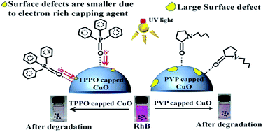
Surface defects are potential sites for modifying the activities of photoexcited electrons and holes, and may consequently affect photocatalytic activity. Here we have demonstrated how surface defects in copper oxide nanoparticles can be engineered by electron rich capping agent (like TPPO) to drastically improve the rate of photocatalytic degradation of rhodamine B dye. The steady state photoluminescence spectroscopy indicated metal vacancies and cluster vacancy defects in the as synthesized batches of bare, PVP (polyvinylpyrrolidone) capped and TPPO (triphenylphosphine oxide) capped copper oxide nanoparticles (NPs). The positron annihilation lifetime spectroscopy studies confirmed that these electron deficient defects were mainly located at the grain boundaries. As compared to the bare and the PVP capped CuO NPs, the positron lifetime parameter ‘τ1’ for TPPO capped CuO NPs was significantly small, which is due to faster annihilation of positrons trapped in free volume defect sites by the local electrons. Unlike PVP, the electron rich TPPO is capable of transporting more electrons to the electron deficient defect sites, due to which the rate of photocatalytic dye degradation was three to four folds higher for the TPPO capped CuO NPs (k = 0.556 h−1) than polyvinylpyrrolidone (PVP) capped CuO NPs (k = 0.168 h−1) and bare CuO NPs (k = 0.143 h−1). The reduced rate of photocatalytic dye degradation for bare and PVP capped CuO NPs were attributable to trapping of photoexcited electrons at the defect sites. The photocatalytic dye degradation was associated with generation of hydroxyl radicals and H2O2 species. The maximum photocatalytic dye degradation by TPPO capped CuO NPs was corroborated with highest concentration of H2O2 detection (125 μM), followed by 79 μM for PVP capped CuO NPs and 65 μM for bare CuO NPs. A detailed mechanism of the role of defects in photocatalytic process has been outlined.

1. Introduction

The discovery of TiO2 as a photocatalyst by Fujishima and Honda in 1972 led to its profound applications in wastewater treatment and solar energy.1–8 This class of materials has a unique electronic band structure comprised of a filled valence band (VB) and empty conduction band (CB).9 The photocatalytic application depends on absorption of light energy equal to or greater than the band gap of the material. The wastewater treatment by such semiconductor type materials is attributed to the generation of reactive oxygen species (ROS), e.g., O2˙ (superoxide radicals), H2O2 (hydrogen peroxide) and OH˙ (hydroxyl radicals). These are formed due to the interaction of photoexcited electrons in the conduction band (eCB) and holes in the valence band (hVB+) with O2 and H2O, respectively.10–15 The major drawback of bulk TiO2 as a photocatalyst is attributed to its wide band gap corresponding to the UV region. Consequently, photocatalysts of smaller band gaps are getting more scientific attention. In this regard, CuO is a promising material as a photocatalyst for dye degradation owing to good chemical stability, high resistance to photocorrosion and relatively low cost.16–22 The band gap of bulk CuO is 1.2 eV which correspond to near infrared region. Such a small band gap may pose a limitation for ROS generation owing to enhanced recombination of the electrons and holes. However, the band gap can be tuned to visible region by reducing the particle size of CuO particles to the order of excitonic radius of CuO and satisfying the quantum confinement effect.23 In addition, decrease in particles size would lead to increase in the surface area of the nanoparticles and facilitate enhanced surface reactivity.

Furthermore, defects play important role in photocatalytic activity.24,25 In this regard, method employed for synthesizing nanoparticles can be considered relevant for incorporating defects in nanoparticles. Chemical precipitation method is reasonably simple and reproducible, where the nanoparticles are in situ capped with surfactants or other suitable agents to inhibit agglomeration.26 The choice of capping agents might play an important role for passivating the defect states and dangling bond density at the surface of the nanoparticles, which might be beneficial for improving efficiency of the photocatalytic dye degradation.27 Such studies on role of surface defects of nanoparticles on photocatalytic dye degradation are not systematically reported.

In the present study, we have employed photoluminescence (PL) spectroscopy and positron annihilation lifetime spectroscopy (PALS) as a probe for studying structural defects in bare and capped CuO NPs synthesized by precipitation method. Two different capping agents, e.g., triphenylphosphine oxide (TPPO) and polyvinylpyrrolidone (PVP), were chosen for stabilizing nanoparticles.28,29 Both are polar capping agents that can bind with nanoparticles. The difference is their molecular structure, i.e., TPPO has three bulky phenyl groups while PVP comprises of long C–H chain and pyrrolidone ring, tend to inhibit agglomeration of the nanoparticles. In general, the metal vacancies and oxygen vacancies are well characterized by photoluminescence spectroscopy.30 The PALS study are suitable to characterize void oriented defects in inorganic nanomaterials.31,32 Positron interacts with local electrons and it may either be annihilated to produce two photons of 511 keV energy or it may interact with electron to form a hydrogen-like atom called positronium atom (Ps) which may be trapped in a free volume defect site and are eventually annihilated. Since defect sites are characterized with lower electron density than the defect-free material, so the positron lifetime in a defect rich material is longer and is a measure of the defect size, especially at the grain boundary.33 In the present work, positron lifetimes of the bare and capped CuO NPs were compared for assessing effect of capping on surface defects in CuO NPs. All the batches of CuO NPs were subjected to photocatalytic degradation studies using rhodamine B as a model dye to understand the role of defects in CuO NPs on photocatalytic activity. The photocatalytic degradation of rhodamine B was studied with respect to specific assays related to generation of reactive oxygen species and was correlated with the nature of defects probed by PALS.

2. Experimental

2.1. Chemicals

Copper acetate (Cu(CH3COO)2, >98%), acetic acid (CH3COOH, 99.5%), sodium hydroxide (NaOH, >98%), polyvinylpyrrolidone (PVP, average molecular weight 40[thin space (1/6-em)]000), tertiary butyl alcohol, ammonium oxalate (AO), terephthalic acid and ethanol (>99%) were procured from HiMedia Pvt. Ltd., India. Potassium iodide, ammonium molybdenum, potassium biphthalate, triphenylphosphine oxide (TPPO > 98%) and rhodamine B (Rh B) dye were procured from Sigma Aldrich, GmbH, Germany. All precursors used in this study were of analytical grade and were used without further purification.

2.2. Synthesis of bare and capped CuO nanoparticles

The bare and capped CuO nanoparticles were prepared by the co-precipitation method. Briefly, 150 mL of 2 mM copper acetate aqueous solution was added with 2 mL acetic acid and 0.1 g capping agent (TPPO and PVP) in a round-bottomed flask and refluxed at 100 °C for 1 h. Then 1.0 M NaOH was added to the solution until a black colored precipitate was formed at pH 7–8. The precipitate was centrifuged at room temperature, washed with deionized water (Millipore), followed by washing with ethanol and eventually dried at 60 °C overnight in a temperature controlled oven.

2.3. Characterization of nanoparticles

The X-ray powder diffraction (XRD) patterns were recorded on a Bruker AXS D8 Advance diffractometer using the graphite monochromatized Cu Kα radiation (λ = 1.5406 Å) in a 2θ range from 20° to 80° at a scanning rate of 2° min−1. Transmission electron microscopy (TEM) images were recorded with a FEI Technai-G2 microscope, operated at an acceleration voltage of 200 kV. The sample for TEM measurement was prepared by dropping a highly diluted dispersion of the batches of CuO NPs nanoparticles on respective copper grid of mesh 100. The samples were air dried overnight before measuring by TEM. The morphology and elemental composition was measured by Field Emission-Scanning Electron Microscope coupled with energy dispersive X-ray analysis (FE-SEM coupled with EDX, Zeiss ultraplus) operated at 15 kV. The samples for FE-SEM analysis were prepared by dispersing powdered nanoparticles on a carbon tape and then sputter coated a very thin layer of gold. The UV-visible absorption spectroscopy studies were performed in the wavelength range of 200–800 nm (Shimadzu, UV-1800). The photoluminescence spectra were recorded by Hitachi F-4600 fluorescence spectrophotometer at an excitation energy 300 nm. The positron annihilation lifetime measurements were carried out using a fast–fast coincidence system consisting of two 1 inch tapered off BaF2 scintillators coupled to XP 2020Q photomultiplier tubes. The prompt time resolution of the system using a 60Co source with 22Na gate was 290 ps and measurements were done by using 22Na source embedded in thin Ni-foil. The lifetime spectra were de-convoluted using the code PATFIT88 after incorporating necessary source corrections due to thin Ni foil.34 The Fourier transformed infrared (FT-IR) spectra were recorded on Thermo NICOLET 6700 FTIR in KBr pellets. The Brunauer Emmett and Teller (BET) specific surface area of the nanoparticles were measured by Quantachrome Nova 2200 analyser at liquid nitrogen temperature using nitrogen adsorption–desorption method.

2.4. Photocatalytic degradation of rhodamine B dye

The photocatalytic degradation studies of rhodamine B (RhB) dye were performed at room temperature in 50 mL of dye solution (1 × 10⁻⁵ M) by treating with batches of 1 mg mL−1 of bare and capped CuO NPs, respectively. The respective batches of dye-photocatalyst suspensions were exposed to long UV light (λ = 360 nm) of 30 W at a distance of 30 cm. Prior to the UV light exposure, the dye-photocatalyst suspensions were magnetically stirred for 60 min in the dark to ensure adsorption–desorption equilibrium between the photocatalyst and RhB dye. To differentiate between the photocatalysis and the photolysis of RhB, control experiment under UV light exposure was carried in the absence of NPs as catalyst. In all the cases, the kinetics of decolorization of the dye was studied by withdrawing 1 mL aliquot dye solution at specific time interval. The dye concentration in the supernatant fraction was measured after centrifuging at 15[thin space (1/6-em)]000 rpm at 25 °C for 5 min using Beckman Coulter AllegraTM X-22R.

2.5. ROS generation and ROS scavenging studies

2.5.1 H2O2 determination. The concentration of hydrogen peroxide generated in the reaction medium was determined by the iodide method as given in literature.35 Briefly, the batches of bare and capped CuO photocatalysts were dispersed in water (1 mg mL−1) and exposed to UV light. The aliquots (2–3 mL) of dispersion were drawn after specific time interval and centrifuged. Three millilitre of iodide reagent (0.4 M potassium iodide, 0.06 M NaOH, approximately 10−4 M ammonium molybdate) and 3 mL of 0.1 M potassium biphthalate were added the supernatant. Then the absorbance of the solution was measured by UV-visible spectrophotometer at λ = 351 nm.
2.5.2 Hydroxyl radical (OH˙) assay. The batches of bare and capped CuO photocatalyst of 50 mg were suspended in aqueous solution (50 mL) containing 0.01 M NaOH and 3.0 mM terephthalic acid. The suspensions were magnetically stirred in the dark for 60 min to achieve adsorption–desorption equilibrium between the photocatalyst and terephthalic acid. The solution was exposed to UV light (8 W), kept at a distance of 30 cm for 2 h. Aliquot of 5 mL of the solution was withdrawn and centrifuged. The fluorescence spectrum of the supernatant liquid was measured at λex = 315 nm.
2.5.3 Scavenging of reactive oxygen species (ROS). The effect of ROS generated during photocatalytic reaction was indirectly studied by monitoring dye degradation in the presence of photocatalyst and specific ROS scavenger. Batches of RhB dye solutions were treated with 1 mg mL−1 each of the bare and capped CuO as photocatalysts. The solutions were stirred in dark for 1 h. Then 1 mM tertiary butyl alcohol as OH˙ radical scavenger,36 and 1 mM ammonium oxalate as hole scavenger37 were added to the respective dye solutions and exposed to UV light as discussed above for photocatalytic dye degradation process. At regular interval, aliquot of the dye solution from respective batches of dye degradation media, were take out, centrifuged and the supernatant was measured for dye concentration.

2.6. Stability and reusability of CuO nanoparticles

The stability of catalysts against photocorrosion and reusability of the catalyst was investigated by conducting five degradation cycles with same CuO photocatalyst (bare and capped). For this, 1 mg mL−1 bare and capped CuO NPs were taken in RhB dye solution and the photocatalytic degradation studies were performed. After each cycle, the photocatalyst was separated by centrifuging, washed with distilled water and further used for next cycle. For each cycle studies, the dye-photocatalyst suspension was subjected to 60 min dark stirring followed by photocatalytic degradation in UV light.

3. Results and discussion

3.1. Structural studies

The XRD patterns of bare and capped CuO (by TPPO and PVP, respectively) in Fig. 1, confirmed the synthesis of pure phase monoclinic structure of CuO with Bragg reflections at (110), (002), (111) (20[2 with combining macron]), (020), (202) (11[3 with combining macron]), (002) (31[1 with combining macron]), and (220) planes which matched with the standard JCPDS file (Card no. 48-1548). The XRD pattern revealed peak broadening, attributable to smaller crystallite size and lattice strain in the structure.38 The average crystallite size of the bare and capped CuO NPs calculated from Debye–Scherrer equation are given in Table 1. The TEM analysis of bare CuO revealed formation of spherical shaped nanoparticles of about 17 nm diameter (Fig. 2a), while the particle sizes for PVP capped and TPPO capped CuO NPs were less than 10 nm diameter (Fig. 2b and c). The decrease in the particle size was due to the effect of capping on CuO NPs. The polycrystalline nature of the as synthesized TPPO capped CuO nanoparticle is reflected from the selected area electron diffraction (SAED) pattern (Fig. 3). The FE-SEM images of all the batches of bare and capped CuO NPs revealed agglomeration of the nanoparticles and their chemical composition comprising of is reflected from the characteristic X-rays peaks of Cu and O in the EDS spectrum (given as ESI, Fig. S1a–c). The BET surface area of bare, PVP capped and TPPO capped CuO were measured to be 73.27 m2 g−1, 91.02 m2 g−1 and 105.82 m2 g−1.
image file: c6ra12795a-f1.tif
Fig. 1 X-ray diffraction pattern of bare, PVP and TPPO capped CuO NPs.
Table 1 Positron annihilation lifetime parameters of bare and capped CuO NPs
Sample Crystallite size (nm) τ1 (ps) τ2 (ps) τ3 (ns) I1 (%) I2 (%) I3 (%) τm (ps) χ2
Bare CuO 10.4 160.3 ± 4.2 329.7 ± 3.3 5.6 ± 0.8 31.61 ± 2.23 68.24 ± 2.23 0.14 ± 0.01 283.3 0.95
PVP capped CuO 9.1 162.6 ± 4.5 334.4 ± 3.2 7.6 ± 0.9 30.03 ± 2.18 69.82 ± 2.18 0.14 ± 0.01 293.1 1.08
TPPO capped CuO 8.6 147.7 ± 4.9 325.1 ± 2.9 4.5 ± 0.8 32.99 ± 1.78 66.93 ± 1.77 0.08 ± 0.01 270.2 0.99


image file: c6ra12795a-f2.tif
Fig. 2 Transmission electron microscopy (TEM) of bare, PVP and TPPO capped CuO NPs.

image file: c6ra12795a-f3.tif
Fig. 3 Selected area electron diffraction (SAED) pattern of TPPO capped CuO NPs.

3.2. FT-IR spectra analysis

Fig. S2 represents FT-IR spectra of the bare and the capped CuO nanoparticles recorded in the range of 4000–400 cm−1 (given as ESI). The hygroscopic nature of the CuO nanoparticles is evident for observation of broad peak in the region 3000–3500 cm−1. In the TPPO capped CuO nanoparticles, the band at 1422 cm−1 corresponds to C[double bond, length as m-dash]C stretch corresponding to the aromatic structure of TPPO molecule. A broad and weak peak at 1076 cm−1 is attributed to co-ordinate bond between the oxygen atom of P[double bond, length as m-dash]O bond of TPPO ligand and the Cu2+ ions. A similar FT-IR signature is reported for TOPO-capped TiO2 system.39 The FT-IR spectrum of PVP capped CuO nanoparticles revealed a peak at 1637 cm−1 corresponding to C[double bond, length as m-dash]O stretching of carbonyl group on pyrrolidone ring of PVP. The observed peak position is at lower energy with respect to carbonyl bond which is attributable to C[double bond, length as m-dash]O bond due interaction of carbonyl bond with Cu2+ ion. The peaks observed at 1400 cm−1 and 1340 cm−1 correspond to C–N stretching, while the peak at 1026 cm−1 is attributable to carbon ring in cyclic compounds. Moreover, the peaks at 589 cm−1, 507 cm−1, 440 cm−1 are vibrational frequencies of Cu–O bond.

3.3. Optical spectroscopy studies

The band gaps of the CuO nanoparticles were determined from diffused reflectance spectroscopic study. The Kubelka–Munk (K–M) theory was used to convert reflectance data to absorption mode. The band gap of the samples was estimated from the Tauc's plot, using the Tauc expression:40
 
(αhν)1/n = A(Eg) (1)
where α, , A and Eg are the absorption coefficient, incident light frequency, proportionality constant and band gap, respectively. The value of exponent ‘n’ determines the nature of electronic transition; e.g., n = 1/2 refers to direct transition, and n = 2 refers to indirect transition. Assuming direct transition for CuO nanoparticles, the linear region of the Tauc plot (αhν)2 against was extrapolated to (αhν)2 = 0, which corresponded to the band gap energy of the material (Fig. 4). The band gap for bare, PVP capped and TPPO capped CuO were determined to be 2.59 eV, 2.71 eV and 2.86 eV, which were larger than that of the bulk CuO (1.2 eV). The increase in the band gap is attributable to the decrease in the particle size of the as-synthesized CuO nanoparticles and well supported by TEM results discussed above.

image file: c6ra12795a-f4.tif
Fig. 4 Kubelka–Munk plot for the calculation of band gap of bare, PVP and TPPO capped CuO NPs.

The photoluminescence (PL) spectroscopy was used to investigate the electronic and optical properties of nanoparticles as well as to elucidate the energy levels within the band gap region corresponding to the defect sites.41,42 The emission spectra of bare and capped CuO revealed intense sharp peak at 452 nm, 468 nm and 488 nm (Fig. 5), and our results are consistent with those reported in the literature.43,44 The emission at 468 nm and 488 nm are assigned to energy levels of defect sites, e.g. VCu (copper vacancies), Cui (copper interstitial) and Vo (oxygen vacancy) in CuO nanoparticles.45 The weak emission in bare and PVP capped CuO nanoparticles may be attributed to the non-radiative transition because of the dangling bonds and defects present at the surface of these nanoparticles. In the case of TPPO capping, the increase in the PL intensity increased due to could be attributed to passivation of surface defects and favor radiative recombination.46


image file: c6ra12795a-f5.tif
Fig. 5 Photoluminescence spectra of bare CuO, PVP and TPPO capped CuO NPs.

3.4. Probing defects by positron annihilation lifetime spectroscopy

The as-synthesized bare and capped CuO nanoparticles might possess one or more types of the defects, e.g., copper vacancy (VCu), oxygen vacancy (Vo), Cu interstitial (ICu), voids, cluster defects, triple junction defects, etc. The electron densities at these defect sites are less as compared to the defect free materials or in the bulk of the materials. Since positrons are annihilated with local electrons so positron annihilation lifetime spectroscopy (PALS) is expected to probe these defects except for oxygen vacancies, as the oxygen vacancies exists in neutral charge state. It is important to note two features, e.g., (a) most of the defects probed by positrons are at the grain boundaries and (b) the lifetime of the positrons are more in the defect rich materials.47,48

The recorded positron annihilation lifetime spectra of the batches of bare and capped CuO NPs are given as ESI, Fig. S3 and the different defect sizes were estimated by de-convulating the respective spectrum with three lifetime components, τ1, τ2 and τ3 with their relative intensities I1, I2 and I3, respectively (given in Table 1). The defect sizes due to cation vacancies are expectedly smaller than that of the voids, so the shortest lifetime τ1 is assigned to positron annihilation at grain boundaries due to the presence of copper vacancies (VCu) or VCu clusters. The τ1 values for bare CuO NPs and the one capped with PVP were found to be 160 ± 4 ps and 163 ± 5 ps, respectively. On the other hand, the τ1 for TPPO capped CuO was very small (148 ± 5 ps), and was relatively similar to the bulk CuO reported in literature.49 The longer lifetime (τ1) for PVP capped CuO and bare CuO indicate lesser electron densities at the defect sites, which are primarily attributed as cationic monovacancies, e.g., VCu or smaller sized structural defects e.g., VCu cluster vacancies at the grain boundaries.

It may be remarked that the lone pairs of electrons at the oxygen atoms of TPPO might be sharing with the electron deficient defects sites at the grain boundaries of CuO NPs and thereby neutralized the defects. Notably, the PALS result is consistent with the literature report on p-type CuO comprising Cu vacancies that act as shallow and efficient hole producers.50 The lifetime component τ2 was found to be of similar order (ranging between 325 ± 3 ps and 333 ± 4 ps) for all the studied batches. The lifetime τ2 is attributable to larger sized free volume at the grain boundaries, namely di-vacancies, larger copper vacancy clusters or nanovoids at the intersection of multiple grain boundaries (e.g., triple junctions). The longest lifetime component τ3 is attributable to formation of orthopositronium atoms in free volume defects.33 However, the relative intensities of the τ3 component were negligible as compared to τ1 and τ2 (less than 0.14%) and therefore it is not relevant for interpreting defects in the as-synthesized bare or capped CuO NPs. The mean positron annihilation lifetime (τm) is statistically better reliable parameter for assessing overall defects and it is given as:

 
image file: c6ra12795a-t1.tif(2)

Notably, the mean positron lifetime (τm) was found minimum for the batch of TPPO capped CuO NPs and the maximum mean positron lifetime was found for PVP capped CuO NPs. From these results it may be surmised that the defects owing to Cu monovacancies or divacancies and nanovoids at the grain boundaries were significantly less for TPPO capped CuO NPs as compared to bare CuO NPs and PVP capped CuO NPs. As these defects are electron deficient so the electron density of capping agent would be important for neutralizing the defects. In the case of TPPO capping, the electron deficient defects at the grain boundaries of CuO NPs were likely to be neutralized by the transfer of lone pair of electron on the oxygen of P[double bond, length as m-dash]O. Similar electron transfer process can occur from the carbonyl group of the PVP. It may be remarked that the transfer of electron is more efficient for TPPO than PVP owing to the greater polarization of electrons in the P[double bond, length as m-dash]O bond than C[double bond, length as m-dash]O bond.

3.5. Photocatalytic degradation of rhodamine B dye (RhB dye)

The kinetics of photocatalytic degradation of RhB dye treated with bare and capped CuO NPs under UV light was studied by using Langmuir–Hinshelwood model, given as:51
 
ln(C/Co) = kt, (3)
where ‘Co’ is the initial concentration of the dye solution, ‘C’ is the dye concentration at time ‘t’ and ‘k’ is the pseudo-first order rate constant. The linear plot between ln(Co/C) and time (t) of UV light exposure for all the batches of bare and capped CuO NPs are shown in Fig. 6, which indicated the photocatalytic RhB degradation followed a pseudo first-order kinetics. The degradation rate constant (k), calculated from the slope of ln(Co/C) verses ‘t’ plot, was three folds higher for TPPO capped CuO NPs (k = 0.556 h−1) than PVP capped CuO NPs (k = 0.168 h−1) and bare CuO NPs (k = 0.143 h−1). An interesting correlation could be observed between the rate of dye degradation and its positron lifetime τ1 values in bare and capped CuO NPs. The efficiency of dye degradation was inversely related to the positron lifetime of τ1 component and hence the dye degradation efficiency is related to the structural defects in the photocatalysts.

image file: c6ra12795a-f6.tif
Fig. 6 The plot of ln(Co/C) as a function of time by bare, PVP and TPPO capped CuO NPs.

3.6. Mechanism of photocatalytic dye degradation by CuO NPs

The photocatalytic action of CuO NPs is attributable to sequence of events triggered by absorption of light of suitable energy that is greater than or equal to the band gap of CuO NPs as photocatalyst. Consequently, photoexcited electrons are transferred from valence band to conduction band, leaving the holes at the valence band. Primarily there are two process for the photoexcited electrons and holes, e.g., (a) these charge carriers migrate from bulk to surface, where electrons reduce adsorbed electron acceptor (e.g., O2) and holes oxidize adsorbed donor species (e.g., H2O); (b) the electrons (e) and holes (h+) recombine. Amongst these two processes, the former one may lead to generation of a plethora of reactive oxygen species (ROS) which subsequently cause dye degradation by cleaving the molecular structure of dye.52,53 The feasibility of ROS generation would depend on the favourable combinations of potentials of photogenerated electron and holes with those of following relevant redox reactions:
 
CuO + → CuO (eCB, hVB+) (4)
 
hVB+ + H2O → H+ + OH˙ (5)
 
O2 + eCB → O2 (6)
 
O2 + 2H+ + eCB → H2O2 (7)
 
2H2O + 2hVB+ → 2H2O2 + 2H+ (8)
 
H2O2 → 2OH˙ (9)

The potentials of the photogenerated electrons and holes correspond to the potential energies of the bottom of conduction band (ECB) and the top of valance band (EVB), respectively. These potential energies in a metal oxide nanoparticles can be determined as:54

 
ECB = χ(AaBb) + 1/2Eg + Eo; and EVB = ECB + Eg; (10)
where, Eg is the band gap of the semiconductor, Eo is the scale factor taken as −4.50 eV, i.e., the energy of free electrons on the normal hydrogen electrode (NHE scale). The parameter χ(AaBb) corresponds to the absolute electronegativity of a semiconductor material type AaBb, which is calculated as the geometric mean of the electronegativity of the constituent atoms. In our calculation, the electronegativity values for Cu and O were taken as 4.48 eV, and 7.54 eV respectively.55 The ECB values for bare CuO NPs, PVP capped CuO NPs and TPPO capped CuO NPs were calculated as +0.05, −0.04 and −0.12 eV, respectively. The corresponding EVB values were +2.56, +2.64, +2.74 eV, respectively.

It is noted that the potential energy of ECB for both the batches of capped CuO NPs and bare CuO NPs are lesser than the EH (redox potential) of O2/O2˙ (−0.2 eV vs. NHE).56 Since electrons transit from higher potential to lower potential, so reduction of molecular oxygen to superoxide radicals (O2˙) by the photoexcited electrons is not thermodynamically a favourable process. However, the potentials of photogenerated electrons in CuO NPs are higher than the redox potentials of O2/H2O2 (0.68 V vs. NHE) and H2O/H2O2 (1.80 V vs. NHE).57 It rendered favourable condition for in situ produce H2O2 species which is a storage tank for generating various reactive oxygen species in the photocatalytic processes.58,59 In addition, the EH of H2O/OH˙ (+2.2 eV vs. NHE scale)55 is at a higher potential than that of EVB of all the batches of CuO NPs. This is a favourable condition for holes mediated oxidation of H2O into OH˙ radicals.

The energy levels of the redox couples leading to generation of respective reactive oxygen species e.g., H2O2 and OH˙ for CuO nanoparticles as photocatalyst and their role in subsequent photocatalytic dye degradation of rhodamine B dye is schematically presented in Scheme 1.


image file: c6ra12795a-s1.tif
Scheme 1 Showing a schematic representation of band structure of TPPO capped CuO nanoparticles and various important redox reactions (in NHE scale) relevant for ROS generation and consequential photocatalytic degradation of rhodamine B dye.
3.6.1 Estimation of H2O2 and OH˙. Firstly, concentration of H2O2 generated in the photochemical process by different batches of bare and capped CuO NPs was determined by iodometry and results are given in Fig. 7. Notably, 125 μM H2O2 was produced by TPPO capped CuO, while 79 μM and 65 μM concentrations of H2O2 were formed in the batches of PVP capped CuO NPs and bare CuO NPs. Higher concentrations of OH˙ radicals were produced in the batch of TPPO capped CuO NPs as compared to the PVP capped CuO NPs and bare CuO NPs, which was confirmed from the hydroxyl radical specific terephthalic acid (TA) assay (Fig. 8). In this assay the OH˙ radicals react with (TA) and generate 2-hydroxyterephthalic acid (TAOH), which emits a unique fluorescence signal with a peak at 426 nm when excited at 315 nm.60
image file: c6ra12795a-f7.tif
Fig. 7 H2O2 produced as function of time by iodometric method with bare, PVP and TPPO capped.

image file: c6ra12795a-f8.tif
Fig. 8 Fluorescence spectra of TAOH solution after treating with bare, PVP and TPPO capped CuO.
3.6.2 Inhibition of photocatalytic dye degradation by ROS scavenging strategies. The role of reactive oxygen species towards dye degradation was further studied from inhibition of degradation of RhB dye by CuO NPs in the presence of tertiary butyl alcohol and ammonium oxalate as scavengers of OH˙ and photogenerated holes, respectively and the results are given given as ESI, Fig. S4. The RhB dye degradation is remarkably suppressed with the addition of ammonium oxalate, which is reflected from the decrease in the rate of dye degradation from k = 0.565 h−1 to k = 0.088 h−1. This is attributable to scavenging of photogenerated holes and consequently the ROS generation was limited. Further, the rate of dye degradation decreased from k = 0.565 h−1 to k = 0.101 h−1 in presence of tertiary butyl alcohol, which is a hydroxyl radical scavenger (given as ESI, Fig. S4). The above results confirmed hole mediated hydroxyl radical generation as the major event responsible for degradation of RhB dye.

3.7. Effect of surface defects on photocatalytic degradation

Surface defects in metal oxide NPs are known to influence photocatalytic activity.61,62 The defects can play two different roles, i.e., (a) it can improve the separation of photogenerated electrons and holes so that they are available for ROS generation and cause dye degradation;63, (b) it can also act as a trap centre to neutralize these charge carriers and inhibit photocatalytic dye degradation.64–67

In the case of CuO NPs, the specific rate constant for TPPO capped CuO NPs was marginally higher (i.e. 0.005 g m−2 h−1) than PVP capped CuO NPs (0.002 g m−2 h−1) and bare CuO NPs (0.002 g m−2 h−1). It implied that the effect of large surface area of TPPO capped CuP NPs could not be ruled out. In addition, the nature of defects in the batches of bare and capped CuO nanoparticles would impact the rate of photocatalytic degradation. Comparing the parameters obtained from PALS studies and photocatalytic dye degradation, it is found that positron lifetime (τ1) is inversely correlated with the rates of photocatalytic dye degradation. The enhanced photocatalytic dye degradation by TPPO capped CuO NPs was associated with smaller free-volume defects reflected from the τ1 component of PALS, which is characteristic of Cu monovacancies or smaller clusters of Cu vacancies at the grain boundaries.

Further, the intensities (I1) of τ1 are of similar order for all batches of capped and bare CuO NPs, so the population of defects in these batches of CuO are not relevant. In other words, it may be remarked that larger τ1 values (for PVP capped and bare CuO) indicated larger free-volumes corresponding to copper vacancy defects at grain boundaries as compared to smaller τ1 value (for TPPO capped CuO). It may be remarked that the larger copper vacancy defects at the grain boundaries of PVP capped CuO NPs and bare CuO NPs were better trapping sites for neutralizing the photogenerated charge carriers. This would explain the reason for less ROS generation and consequently less efficient photocatalytic dye degradation by PVP capped CuO and bare CuO NPs. Whereas, smaller τ1 component in TPPO capped CuO NPs corresponds to reduced Cu vacancies defects, which is not favourable for trapping the photogenerated charge carriers and hence facilitate the generation of hydroxyl radical for enhanced photocatalytic reaction. It may be commented here that the defects owing to oxygen vacancies (if any) were not probed by positron lifetime spectroscopy and hence its effect on the rate of photocatalytic activity of CuO NPs could not be assessed. However, the oxygen vacancies in CuO might not be very important as its energy level below the conduction band is not convenient for electron transfer process for bringing out reduction of oxygen to superoxide radical species.

3.8. Stability of CuO nanoparticles

In order to investigate the photostability and re-usability of CuO NPs, the five cycles of photodegradation process (i.e., equilibration in dark followed by UV light exposure) were repeated. In all the five cycles, same percentage of degradation of RhB dye was achieved in 5 h of UV light exposure and their respective rate constants (k) found to be of similar order (given as ESI, Fig. S5). A stable photocatalytic performance has been observed and our result complimented the literature report on the stability of CuO against photocorrosion.19 These results are encouraging to design supported photocatalyst made of CuO NPs for undertaking large volume textile dye degradation.

4. Conclusion

Highly crystalline batches of bare, PVP capped and TPPO capped CuO NPs of diameter less than 10 nm were synthesized by chemical precipitation method. The band gaps of these nanoparticles were in the range of 2.59 and 2.86 eV, and which are suitable as photocatalyst for rhodamine blue dye degradation under the exposure of light with λ = 360 nm. Overall, the photocatalytic dye degradation was correlated with in situ generation of H2O2 and OH˙ in the reaction medium via interaction with photogenerated holes. The systematic variation in the photocatalytic dye degradation was correlated with structural defects like metal vacancies and cluster vacancies at the grain boundaries of the nanoparticles, as revealed from positron annihilation lifetime spectroscopy. The surface defects were considered as trapping sites of photogenerated electrons and holes, that lead to less ROS generation and subsequent slowing down of photocatalytic dye degradation by PVP capped CuO and bare CuO NPS. In the case of TPPO capped CuO NPs, the capping agent is electron rich, which could passivate the surface defects, and consequently exhibited enhanced photocatalytic degradation of rhodamine B as a model dye.

Acknowledgements

A. S. is thankful to Ministry of Human Resource Development (MHRD), Govt of India for awarding Senior Research Fellowship. R. K. D is thankful to Board of Research in Nuclear Sciences (BRNS), Government of India for financial support (2011/37C/37/BRNS).

References

  1. A. Fujishima and K. Honda, Nature, 1972, 238, 37–38 CrossRef CAS PubMed.
  2. B. O'regan and M. Grätzel, Nature, 1991, 353, 737–740 CrossRef.
  3. M. Ge, C. Cao, J. Huang, S. Li, Z. Chen, K.-Q. Zhang, S. S. Al-Deyabd and Y. J. Lai, J. Mater. Chem. A, 2016, 4, 6772–6801 CAS.
  4. Q. Guo, C. Zhou, Z. Ma, Z. Ren, H. Fan and X. Yang, Chem. Soc. Rev., 2016, 45, 3701–3730 RSC.
  5. A. Kudo and Y. Misekia, Chem. Soc. Rev., 2009, 38, 253–278 RSC.
  6. X. Li, J. Yu, J. Low, Y. Fang, J. Xiao and X. Chen, J. Mater. Chem. A, 2015, 3, 2485–2534 CAS.
  7. I. Paramasivam, H. Jha, N. Liu and P. Schmuki, Small, 2012, 8, 3073–3103 CrossRef CAS PubMed.
  8. J. Zhang, Y. Wu, Y. Xing, S. A. K. Leghari and S. Sajjad, Energy Environ. Sci., 2010, 3, 715–726 CAS.
  9. S. G. Kumar and L. G. Devi, J. Phys. Chem. A, 2011, 115, 13211–13241 CrossRef CAS PubMed.
  10. H. Zhang, G. Chen and D. W. Bahnemann, J. Mater. Chem., 2009, 19, 5089–5121 RSC.
  11. A. D. Paola, E. García-López, G. Marcì and L. Palmisano, J. Hazard. Mater., 2012, 211–212, 3–29 CrossRef PubMed.
  12. M. R. Mohamed, D. L. McKinney and W. M. Sigmund, Mater. Sci. Eng., R, 2012, 73, 1–13 CrossRef.
  13. Y. Wang, Q. Wang, X. Zhan, F. Wang, M. Safdar and J. He, Nanoscale, 2013, 5, 8326–8339 RSC.
  14. H. Zhang, Z. Ji, T. Xia, H. Meng, C. Low-Kam, R. Liu, S. Pokhrel, S. Lin, X. Wang, Y. P. Liao, M. Wang, L. Li, R. Rallo, R. Damoiseaux, D. Telesca, L. Mädler, Y. Cohen, J. I. Zink and A. E. Nel, ACS Nano, 2012, 6, 4349–4368 CrossRef CAS PubMed.
  15. Y. Li, W. Zhang, J. Niu and Y. Chen, ACS Nano, 2012, 6, 5164–5173 CrossRef CAS PubMed.
  16. Y. Lu, X. Liu, K. Qiu, J. Cheng, W. Wang, H. Yan, C. Tang, J.-K. Kim and Y. Luo, ACS Appl. Mater. Interfaces, 2015, 7, 9682–9690 CAS.
  17. P. S. Kumar, M. Selvakumar, S. G. Babu, S. K. Jaganathan, S. Karuthapandian and S. Chattopadhyay, RSC Adv., 2015, 5, 57493–57501 RSC.
  18. P. V. Kamat, K. Tvrdy, D. R. Baker and J. G. Radich, Chem. Rev., 2010, 110, 6664–6688 CrossRef CAS PubMed.
  19. Q. Zhang, K. Zhang, D. Xu, G. Yang, H. Huang, F. Nie, C. Liu and S. Yang, Prog. Mater. Sci., 2014, 60, 208–337 CrossRef CAS.
  20. X. Zhao, P. Wang and B. Li, Chem. Commun., 2010, 46, 6768–6770 RSC.
  21. A. S. Zoolfakar, R. A. Rani, A. J. Morfa, A. P. O'Mullaned and K. Kalantar-zadeh, J. Mater. Chem. C, 2014, 2, 5247–5270 RSC.
  22. A. Sharma and R. K. Dutta, RSC Adv., 2015, 5, 43815–43823 RSC.
  23. C. Q. Sun, T. P. Chen, B. K. Tay, S. Li, Y. B. Zhang, H. Huang, L. K. Pan, S. P. Lau and X. W. Sun, J. Phys. D: Appl. Phys., 2001, 34, 3470 CrossRef CAS.
  24. Y. Zhao, H. Shi, M. Chen and F. Teng, CrystEngComm, 2014, 16, 2417–2423 RSC.
  25. K. Rajeshwar, A. Thomas and C. Janáky, J. Phys. Chem. Lett., 2015, 6, 139–147 CrossRef CAS PubMed.
  26. A. Kubacka, M. Fernandez-García and G. Colon, Chem. Rev., 2012, 112, 1555–1614 CrossRef CAS PubMed.
  27. J. Li, Y. Yu and L. Zhang, Nanoscale, 2014, 6, 8473–8488 RSC.
  28. K. M. Koczkur, S. Mourdikoudis, L. Polavarapu and S. E. Skrabalak, Dalton Trans., 2015, 44, 17883–17905 RSC.
  29. M. Green, J. Mater. Chem., 2010, 20, 5797–5809 RSC.
  30. R. K. Dutta, B. P. Nenavathu and S. Talukdar, Colloids Surf., B, 2014, 114, 218–224 CrossRef CAS PubMed.
  31. R. A. Pethrick, Prog. Polym. Sci., 1997, 22, 1–47 CrossRef CAS.
  32. S. Dutta, S. Chattopadhyay, A. Sarkar, M. Chakrabarti, D. Sanyal and D. Jana, Prog. Mater. Sci., 2009, 54, 89–136 CrossRef CAS.
  33. R. Krause-Rehberg and H. S. Leipner, Positron Annihilation in Semiconductors: Defect Studies, Springer, Heidelberg, 1999 Search PubMed.
  34. N. V. Kiassen, D. Marchington and H. C. E. McGowant, Anal. Chem., 1994, 66, 2921–2925 CrossRef.
  35. R. K. Dutta, B. P. Nenavathu and M. K. Gangishetty, J. Photochem. Photobiol., B, 2013, 126, 105–111 CrossRef CAS PubMed.
  36. S. Challagulla, R. Nagarjuna, R. Ganesan and S. Roy, ACS Sustainable Chem. Eng., 2016, 4, 974–982 CrossRef CAS.
  37. Y. Zhang, N. Zhang, Z.-R. Tang and Y.-J. Xu, Chem. Sci., 2013, 4, 1820–1824 RSC.
  38. J. D. Makinson, J. S. Lee, S. H. Magner, R. J. D. Angelis, W. N. Weins and A. S. Hieronymus, Adv. X-Ray Anal., 2000, 42, 407–411 CAS.
  39. J. Bouclé, S. Chyla, M. S. P. J. Shaffer, R. Durrant, D. D. C. Bradley and J. Nelson, Adv. Funct. Mater., 2008, 18, 622–633 CrossRef.
  40. J. Tauc, R. Grigorovic and A. Vancu, Phys. Status Solidi, 1966, 15, 627–637 CrossRef CAS.
  41. J. Shi, H. Cui, Z. Liang, X. Lu, Y. Tong, C. Su and H. Liu, Energy Environ. Sci., 2011, 4, 466–470 CAS.
  42. J. Jiang, L. Zhang, H. Li, W. He and J. J. Yin, Nanoscale, 2013, 5, 10573–10581 RSC.
  43. U. K. Gaur, A. Kumar and G. D. Varma, CrystEngComm, 2014, 16, 3005–3014 RSC.
  44. Y. Wang, T. Jiang, D. Meng, J. Kong, H. Jia and M. Yu, RSC Adv., 2015, 5, 16277–16283 RSC.
  45. A. Bhaumik, A. M. Shearin, R. Patel and K. Ghosh, Phys. Chem. Chem. Phys., 2014, 16, 11054–11066 RSC.
  46. P. S. Chethan, M. P. Joshi, S. R. Mohan, T. S. Dhami, J. Khatei, K. S. K. Rao, L. M. Kukreja and G. Sanjeev, Adv. Mater. Lett., 2013, 4, 454–457 Search PubMed.
  47. A. Roychowdhury, S. P. S. Chakrabarti and B. K. Dutta, J. Hazard. Mater., 2004, 112, 269–278 CrossRef PubMed.
  48. J. Yan, G. Wu, N. Guan, L. Li, Z. Li and X. Cao, Phys. Chem. Chem. Phys., 2013, 15, 10978–10988 RSC.
  49. R. Pareja and R. M. D. L. Cruz, J. Mater. Sci., 1991, 26, 593–596 CrossRef CAS.
  50. D. Wu, Q. Zhang and M. Tao, Phys. Rev. B: Condens. Matter Mater. Phys., 2006, 73, 235206 CrossRef.
  51. S. Chakrabarti and B. K. Dutta, J. Hazard. Mater., 2004, 112, 269–278 CrossRef CAS PubMed.
  52. T. Tachikawa and T. Majima, Langmuir, 2009, 25, 7791–7802 CrossRef CAS PubMed.
  53. A. Lipovsky, Z. Tzitrinovich, H. Friedmann, G. Applerot, A. Gedanken and R. Lubart, J. Phys. Chem. C, 2009, 113, 15997–16001 CAS.
  54. R. G. Pearson, Inorg. Chem., 1988, 27, 734–740 CrossRef CAS.
  55. P. J. Wardman, J. Phys. Chem. Ref. Data, 1989, 18, 1637–1755 CrossRef CAS.
  56. O. Augusto and S. Miyamoto, Oxygen Radicals and Related Species, in Principles of Free Radical Biomedicine, ed. K. Pantopoulos and H. Schipper, Nova Science Publishers, New York, 2012, pp. 19–42 Search PubMed.
  57. J. Chen, D. Li, J. Wang, P. Wang, C. Cao, Y. Shao, J. Wang and J. Xian, Appl. Catal., B, 2015, 163, 323–329 CrossRef CAS.
  58. J. Yi, C. Bahrini, C. Schoemaecker, C. Fittschen and W. Choi, J. Phys. Chem. C, 2012, 116, 10090–10097 CAS.
  59. H. H. Yang and R. L. McCreery, J. Electrochem. Soc., 2000, 147, 3420–3428 CrossRef CAS.
  60. B. P. Nenavathu, A. V. R. K. Rao, A. Goyal, A. Kapoor and R. K. Dutta, Appl. Catal., A, 2013, 459, 106–113 CrossRef CAS.
  61. G. Dong, K. Zhao and L. Zhang, Chem. Commun., 2012, 48, 6178–6180 RSC.
  62. D. Chen, Z. Wang, T. Ren, H. Ding, W. Yao, R. Zong and Y. Zhu, J. Phys. Chem. C, 2014, 118, 15300–15307 CAS.
  63. A. L. Stroyuk, A. I. Kryukov, S. Y. Kuchmii and V. D. Pokhodenko, Theor. Exp. Chem., 2005, 41, 207–228 CrossRef CAS.
  64. G. Dong and L. Zhang, J. Mater. Chem., 2012, 22, 1160–1166 RSC.
  65. P. Zhang, J. Zhang and J. Gong, Chem. Soc. Rev., 2014, 43, 4395–4422 RSC.
  66. G. Dong, Z. Ai and L. Zhang, RSC Adv., 2014, 4, 5553–5560 RSC.
  67. M. Kong, Y. Li, X. Chen, T. Tian, P. Fang, F. Zheng and X. Zhao, J. Am. Chem. Soc., 2011, 133, 16414–16417 CrossRef CAS PubMed.

Footnote

Electronic supplementary information (ESI) available. See DOI: 10.1039/c6ra12795a

This journal is © The Royal Society of Chemistry 2016