Nickel sulfide counter electrode modified with polypyrrole nanoparticles to enhance catalytic ability for flexible dye-sensitized solar cells

Gentian Yue*a, Peng Li*b, Fumin Lia and Chong Chena
aKey Laboratory of Photovoltaic Materials of Henan, School of Physics & Electronics, Henan University, No. 1, Jinming Rd., Kaifeng, 475004, China. E-mail: yuegentian@126.com; Tel: +86 371 23881602
bCollege of Mechanical Engineering and Automation, Huaqiao University, No. 668, Jimei Rd., Xiamen, 361021, China. E-mail: lipengcad@163.com

Received 24th April 2016 , Accepted 16th June 2016

First published on 17th June 2016


Abstract

An efficient counter electrode (CE) of nickel sulfide/polypyrrole/titanium foil (NiS/PPy/Ti) with excellent electrochemical catalytic ability was prepared and used as a platinum (Pt)-free CE for flexible dye-sensitized solar cells (FDSSCs). The surface morphology of the NiS/PPy/Ti CE was characterized by scanning electron microscopy. The electrochemical performance was also characterized according to a series of electrochemical tests which indicated that the NiS/PPy/Ti CE showed great electrocatalytic ability and low charge transfer resistance compared to the Pt/Ti electrode in an iodide/triiodide electrolyte. As a result, the FDSSC based on the NiS/PPy/Ti CE exhibited a high light–electric conversion efficiency of 7.66% under 100 mW cm−2 illumination, comparable to that of the Pt/Ti-based FDSSC (7.31%). Furthermore, the FDSSC based on the NiS/PPy/Ti counter electrode had increased short-circuit current density and is very stable.

1. Introduction

Dye-sensitized solar cells (DSSCs), consisting of one TiO2 photoanode adsorbed dye, one redox mediator of iodide/triiodide (I/I3) and one platinum (Pt) catalyst to complete the redox reaction,1 have attracted great attention for their feasibility, low cost and high efficiency since 1991. Though Pt has a good catalytic activity and provides over 13% light-electric conversion efficiencies for DSSCs,2 it is an expensive metal, hence, researchers are seeking economic, stable, highly electrically conductive and superior electrocatalytic counter electrode (CE) materials. A range of alternative materials to Pt including carbon materials, conducting polymers, transition metal sulfides, nitrides, carbides and alloys have often been reported.3–10 Among them, nickel sulfide (NiS) displays reasonable electrocatalytic activity for the redox couples, comparable to that of the Pt CE.11–13 Lin et al.14 prepared a highly transparent NiS CE on polyimide as a Pt- and transparent conductive oxide (TCO)-free flexible CE for DSSCs by using an electrodeposition technique and presented a good photovoltaic performance for thiolate/disulfide mediated DSSCs. Therefore, NiS is a strong potential candidate for an efficient CE in electronics, optoelectronics, and memory devices. Also, polypyrrole (PPy), due to its superior catalytic ability and economic, stable, and simple fabrication process, is considered to be one of the most promising conducting polymers for efficient CE materials in optoelectronic devices.15–18 Besides, flexible DSSCs (FDSSCs) are the inevitable trend for DSSC practical development since their shape or surface can be devised and constructed as needed using the techniques of large-scale roll-to-roll processing and rapid coating, which could be a promising solution for many impending energy and environmental issues.

Thus, in this work, it is envisaged that titanium foil (Ti) as the flexible substrate will improve the conductive performance, and the NiS/Ti CE with PPy nanoparticles decorated will serve as a Pt-free CE in FDSSCs. The NiS/PPy/Ti CE showed enhanced electrocatalytic activity and low charge transfer resistance, demonstrated by the results of the cyclic voltammetry (CV) and electrochemical impedance spectroscopy (EIS) measurements. The FDSSC fabricated with the NiS/PPy/Ti CE exhibited a greatly improved light-electric conversion performance of 7.66% under 100 mW cm−2 irradiation.

2. Experimental

2.1 Preparation of NiS/PPy/Ti CE

The NiS/PPy/Ti CE was prepared by using a two-step electrochemical/chemical process as follows. Firstly, cleaned Ti foil was immersed in 0.05 M NiCl2 and 1.0 M TU polymerization solution to carry out the electrodeposition at a constant potential of −1.2 V vs. Ag/AgCl at room temperature (about 25 °C) with an exposed area of 0.8 × 0.8 cm2. Secondly, the obtained NiS/Ti CE was immersed in a freshly prepared solution consisting of [Py][thin space (1/6-em)]:[thin space (1/6-em)][Fe3+] = 1[thin space (1/6-em)]:[thin space (1/6-em)]1, and then 1 ml of 25.1 g l−1 (NH4)2S2O8 solution was fast added into it, and the solution was kept for 4 hours at 4 °C, resulting in an in situ polymerization reaction of PPy nanoparticles on the NiS/Ti surface. The obtained NiS/PPy/Ti electrode was put into anhydrous ethanol for 1 h and a vacuum oven at 100 °C for 6 h, respectively. For comparison, Pt, PPy and NiS CEs were also coated on Ti substrates using a similar electrodeposition approach. The Ti substrates were soaked in 0.01 M H2PtCl6 ethanol solution containing a suitable amount of LiClO4 to carry out the Pt/Ti CE electrodeposition procedure. The clean Ti foil was immersed in a freshly prepared solution consisting of [Py][thin space (1/6-em)]:[thin space (1/6-em)][Fe3+] = 1[thin space (1/6-em)]:[thin space (1/6-em)]1 and 1 ml of 25.1 g l−1 (NH4)2S2O8 solution, and kept for 4 hours at 4 °C to enable the PPy/Ti CE in situ polymerization reaction.

2.2 Fabrication of the FDSSC

A TiO2 anode was prepared as we reported previously.19,20 Briefly, a certain amount of treated P25, absolute ethanol and distilled water were mixed with a molar ratio of 1[thin space (1/6-em)]:[thin space (1/6-em)]5[thin space (1/6-em)]:[thin space (1/6-em)]1 and added to an autoclave (packing volume <80%) followed by a hydrothermal treatment at 200 °C for 24 h under stirring, then cooling to room temperature, the resultant slurry was concentrated down to 1/4 of its original volume, then polyvinylidene fluoride (10 wt% slurry) binder was added to form a TiO2 colloid. Thus a homogeneous and stable TiO2 colloid was obtained. TiO2 with a particle size of 10–20 nm was coated on an ITO/PEN substrate by using a doctor-scraping technique. The TiO2/ITO/PEN film was irradiated under UV light for 30 min, and then heated in a vacuum oven at 80 °C for 1 h. The process was repeated twice. The dye was loaded by immersing the obtained TiO2/ITO/PEN film in a 0.3 mM dye Z907 tert-butanol/acetonitrile solution for 24 h. Thus a flexible dye-sensitized photoanode was obtained. The FDSSC was fabricated by injecting the liquid electrolyte (0.05 M I2, 0.1 M LiI, 0.6 M tetrabutylammonium iodide and 0.5 M TBP in acetonitrile) in the aperture between the dye-sensitized TiO2/ITO/PEN electrode and the NiS/PPy/Ti CE. The two electrodes were clipped together and wrapped with thermoplastic hot-melt Surlyn.

2.3 Characterization

The surface morphology of the sample was observed by using a JSM-7001F field emission scanning electron microscope. The crystal structure was explored by using glancing incident X-ray diffraction (GIXRD, Rigaku-TTRAXIII) analysis. EIS was carried out under simulated open-circuit conditions (CHI 660E, CH Instrument) in an ambient atmosphere, sealing with thermoplastic hot-melt Surlyn and leaving an exposed area of 0.64 cm2. The frequency of the applied sinusoidal AC voltage signal was varied from 0.1 Hz to 105 Hz and the corresponding amplitude was kept at 5 mV in all cases. The photovoltaic testing of the FDSSC with an exposed area of 0.25 cm2 was carried out by measuring the photocurrent–photovoltage (JV) character curve under white light irradiation of 100 mW cm−2 from a solar simulator (XQ-500W, Shanghai Photoelectricity Device Company, China) in an ambient atmosphere. The fill factor (FF) and the photo-electric conversion efficiency (η) of the FDSSC were calculated according to the following equations:
 
image file: c6ra10585h-t1.tif(1)
 
image file: c6ra10585h-t2.tif(2)
where Jsc is the short-circuit current density (mA cm−2); Voc is the open-circuit voltage (V); Pin is the incident light power (mW cm−2) and Jmax (mA cm−2) and Vmax (V) are the current density and voltage at the point of maximum power output in the JV curves, respectively.

3. Results and discussion

3.1 Surface morphology of the samples

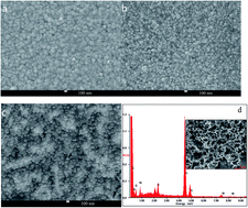
Fig. 1a shows the scanning electron microscopy (SEM) image of the NiS/Ti CE, from which it can be seen clearly that the NiS was uniformly coated on the Ti foil. PPy particles of various sizes unevenly coated on the Ti foil are shown in Fig. 1b. As shown in Fig. 1c, the NiS/PPy nanoparticles of a similar size are close to the Ti foil surface after being modified by the PPy nanoparticles, which possess a smooth but concave convex surface morphology. This largely increases the contact area of the CE and enables the adsorption of the liquid electrolyte, further strengthening and improving its electrocatalytic activity for the I/I3 redox reaction. EDS was carried out and is shown in Fig. 1d to further identify the compositions of the NiS/PPy/Ti CE. The inset in Fig. 1d is the region where the EDS data was obtained. C, O, N, Ni, S and Ti elements are present, and the ratio of atomic percentages of Ni[thin space (1/6-em)]:[thin space (1/6-em)]S is nearly 1[thin space (1/6-em)]:[thin space (1/6-em)]1. This illustrates that NiS/Ti CE was successfully modified by PPy nanoparticles.
image file: c6ra10585h-f1.tif
Fig. 1 SEM images of NiS/Ti (a), PPy/Ti (b), and NiS/PPy/Ti (c) CEs and EDS of the NiS/PPy/Ti CE (d).

Fig. 2 presents the XRD patterns of the NiS/PPy/Ti CE. The only broad characteristic peak at about 22° of PPy exhibits that PPy is amorphous.21 Besides, the diffraction peaks of NiS located at 32.22°, 35.67°, 45.83°, 56.09° and 75.32° are observed, corresponding to the crystal planes of (100), (101), (102), (110) and (202) (JCPDS no. 89-1957), respectively. The diffraction peaks at 35.57°, 37.39°, 40.45°, and 52.64° are attributed to the Ti foil. These results indicate that the NiS/PPy/Ti CE was successfully prepared affirming the SEM results.


image file: c6ra10585h-f2.tif
Fig. 2 XRD pattern of the NiS/PPy/Ti CE.

3.2 Electrochemical properties

Fig. 3a compares the CVs for the various CEs in the I/I3 electrolyte at a scan rate of 50 mV s−1. We can see that all the CEs exhibit a perfect reversible response and rapid electron-transfer kinetics but different cathodic peak current densities (Ipc) and cathodic peak potentials (Vpc). From Fig. 3, we can see that the NiS/PPy/Ti CE possesses three pairs of redox peaks compared with the Pt CE, indicating it has a perfect reversible response. Moreover, among the three pairs of redox peaks, the one in the potential interval of −0.4 to 0.4 V, is vital for its operation in DSSCs and is responsible for the reaction I3 + 2e → 3I.22 The NiS/PPy/Ti CE in the potential interval of −0.4 to 0.4 V exhibits more negative Vpc and higher anodic and cathodic peak current density than the Pt/Ti, PPy/Ti and NiS/Ti CEs (listed in Table 1), indicating that the composite CE has excellent Pt-like catalytic activity for the reduction of I3 to I and superior electrocatalytic activity towards the reduction of I3.22 The enhanced electrocatalytic activity of NiS/PPy/Ti CE is mainly caused by the synergistic catalytic effect of PPy and NiS, as well as the intrinsically excellent electrocatalytic activity and the concave convex microstructure of the NiS/PPy/Ti CE.22 Fig. 3b shows the 40 cycle CV test and exhibits the stable anodic and cathodic peak current densities for the curves. The results indicate excellent electrochemical stability in the I/I3 electrolyte for the NiS/PPy/Ti CE.23
image file: c6ra10585h-f3.tif
Fig. 3 CVs for the Pt/Ti, PPy/Ti, NiS/Ti and NiS/PPy/Ti electrodes at a scan rate of 50 mV s−1 (a); and the stable performance of the NiS/PPy/Ti electrode after a 40 cycle CV test (b).
Table 1 Electrochemical parameters obtained from the impedance spectra and CVs of the various CEs
CEs Rs (Ω cm2) Rct (Ω cm2) Zw (Ω cm2) Ipc (mA cm−2) Vpc (V)
Pt/Ti 4.25 3.46 1.17 −3.04 −0.27
PPy/Ti 5.91 5.06 1.78 −2.96 −0.49
NiS/Ti 5.15 4.14 1.40 −2.59 −0.18
NiS/PPy/Ti 4.65 3.32 1.58 −3.28 −0.15


To further investigate the electrocatalytic ability of the different CEs for regeneration of the I/I3 redox couple, the Nyquist plots of the Pt, PPy/Ti, NiS/Ti and NiS/PPy/Ti electrodes are shown in Fig. 4 and the corresponding parameters are listed in Table 1. From Fig. 4, the results show two well-defined semicircles over the high and low frequency ranges. The series resistance (Rs) is determined at the high frequency range of the impedance spectra, where the phase is zero. The first semicircle is assigned to the charge-transfer resistance (Rct) for the I3 reduction at the CE|electrolyte interface, and the second semicircle at low frequency represents the Nernst diffusion impedance (Zw) corresponding to the diffusion resistance of the I/I3 redox species.24,25 We can see that the Rs values of the Pt/Ti, NiS/Ti and NiS/PPy/Ti electrodes are similar except for the PPy/Ti CE, indicating good combination between the catalysts and the substrate. The NiS/PPy/Ti CE exhibits a lower Rct of 3.32 Ω cm2 compared to the Pt/Ti electrode (3.46 Ω cm2), and much lower than that of the PPy/Ti (5.06 Ω cm2) and NiS/Ti (4.14 Ω cm2) CEs, revealing an improvement in electrocatalytic activity and conductivity for the composite CE due to the synergistic effect of PPy and NiS. In addition, the Zw values of the various CEs are very similar but there are some differences. The distinctions can be attributed to the relatively low conductivity of PPy compared to that of the Pt and NiS catalyst.


image file: c6ra10585h-f4.tif
Fig. 4 EIS of the symmetrical Pt/Ti, PPy/Ti, NiS/Ti and NiS/PPy/Ti electrodes for the I/I3 reaction.

3.3 Photovoltaic performance of the FDSSCs

Fig. 5a gives the photocurrent density–voltage (JV) curves of the FDSSCs under illumination of 100 mW cm−2, and the photovoltaic characteristics including short-circuit current (Jsc), open-circuit voltage (Voc), fill factor (FF), and light–electric conversion efficiency (η) are summarized in Table 2. The above mentioned light–electric conversion efficiency can be directly observed from Fig. 5b. The FDSSC employing the NiS/PPy/Ti CE achieves a Jsc of 16.13 mA cm−2, higher than that of the FDSSC with the Pt CE, and a corresponding η of 7.66%, compared to that of the Pt-based FDSSC (7.31%). The Voc (0.72 V) and FF (0.66) for the FDSSC with the NiS/PPy/Ti CE are both higher than those of the FDSSCs based on the NiS/Ti and PPy/Ti CEs, and approaching those of the Pt-based FDSSC (Voc of 0.73 V and FF of 0.68). This might be attributed to the smooth but concave convex surface structure and the intrinsically excellent electrocatalytic activity of the NiS/PPy/Ti CE, which provide 3D electrocatalytic surfaces with larger active surface areas and superior catalytic ability for the I3 reduction.26
image file: c6ra10585h-f5.tif
Fig. 5 The photovoltaic performance of the FDSSCs fabricated with different CEs under standard illumination.
Table 2 EIS parameters and photoelectric properties of the FDSSCs with various CEs
FDSSCs Rct1 (Ω cm2) Rct2 (Ω cm2) Voc (V) Jsc (mA cm−2) FF η (%)
Pt/Ti-based 4.06 6.38 0.73 14.72 0.68 7.31
PPy/Ti-based 7.66 21.51 0.64 13.05 0.64 5.35
NiS/Ti-based 6.12 10.54 0.71 13.81 0.65 6.37
NiS/PPy/Ti-based 3.79 8.28 0.72 16.13 0.66 7.66


Fig. 6 exhibits the EIS of the FDSSCs to study the dynamics of electron transport and the interfacial characteristics. Similar to the Nyquist plots of the CEs, the EIS of the FDSSCs also show two semicircles over the X-axis. The small semicircle represents the charge transfer resistance (Rct1) corresponding to the charge transfer process occurring at the interface between the CE and the electrolyte, and the large semicircle originates from the charge transfer and recombination resistance (Rct2) related to the electron transport process within the TiO2 film and the charge transfer process at the TiO2/dye/electrolyte interfaces.27,28 From Table 2, we can see that the Rct1 of all the CEs follows the order of PPy/Ti > NiS/Ti > Pt/Ti > NiS/PPy/Ti, implying an excellent electrocatalytic ability for NiS/PPy/Ti in the I/I3 electrolyte. The Rct2 of the NiS/PPy/Ti-based FDSSC is similar to the Pt/Ti-based FDSSC, but much smaller than those of the FDSSCs based on the NiS/Ti and PPy/Ti CEs, denoting superior charge transport characteristics in the FDSSC with the NiS/PPy/Ti CE. This result also proves that the electrocatalytic activity and conductivity of the NiS/PPy/Ti CE can be further enhanced due to the synergistic catalytic effect of NiS and PPy. According to τn(EIS) = Rct2 × Cμ, the electron lifetime values were calculated to be 7.89, 5.57, 6.33, and 8.32 ms for the FDSSCs with Pt/Ti, PPy/Ti, NiS/Ti and NiS/PPy/Ti CEs, respectively. The longer electron lifetime for the NiS/PPy/Ti-based FDSSC than the other FDSSCs indicates more effective suppression of the back reaction between photoelectrons in the conduction band of TiO2 and I3 in the electrolyte, thus reflecting the improvement in light–electric conversion efficiency of the FDSSC with the NiS/PPy/Ti CE.


image file: c6ra10585h-f6.tif
Fig. 6 EIS spectra of FDSSCs based on different counter electrodes.

4. Conclusions

In conclusion, we have demonstrated that the fabrication of a NiS/PPy counter electrode on Ti foil using an in situ synthetic route is an effective strategy for accelerating charge transfer. Extensive electrochemical analyses show that the NiS/PPy/Ti CE possesses amazing electrocatalytic activity for the I/I3 redox reaction and low charge transfer resistance. Under the optimal conditions, the FDSSC with the NiS/PPy/Ti CE produces an impressive light–electric conversion efficiency of 7.66% in comparison with that of 7.31% for the Pt/Ti electrode under full sunlight illumination. In consideration of this facile approach, efficient and low cost, the NiS/PPy/Ti CE shows great potential as a low cost and high performance alternative in the scalable production of FDSSCs.

Acknowledgements

The authors are very grateful to the joint support by the National Natural Science Foundation of China (No. 21401024 and No. U1504624). This work is also supported by China Postdoctoral Science Foundation Funded Project (No. 2015M572102).

References

  1. B. O’Regan and M. Grätzel, Nature, 1991, 353, 737–740 CrossRef.
  2. S. Mathew, A. Yella, P. Gao, R. Humphry-Baker, B. F. E. Curchod, N. Ashari-Astani, I. Tavernelli, U. Rothlisberger, M. K. Nazeeruddin and M. Grätzel, Nat. Chem., 2014, 6, 242–247 CrossRef CAS PubMed.
  3. L. Kavan, J. Yum and M. Grätzel, Nano Lett., 2011, 11, 5501–5506 CrossRef CAS PubMed.
  4. G. T. Yue, X. P. Ma, Q. W. Jiang, F. R. Tan, J. H. Wu, C. Chen, F. M. Li and Q. H. Li, Electrochim. Acta, 2014, 142, 68–75 CrossRef CAS.
  5. G. T. Yue, X. A. Zhang, L. Wang, F. R. Tan, J. H. Wu, Q. W. Jiang, J. M. Lin, M. L. Huang and Z. Lan, Electrochim. Acta, 2014, 129, 229–236 CrossRef CAS.
  6. G. Li, J. Song, G. Pan and X. Gao, Energy Environ. Sci., 2011, 4, 1680–1683 Search PubMed.
  7. M. Wu, J. Bai, Y. Wang, A. Wang, X. Lin, L. Wang, Y. Shen, Z. Wang, A. Hagfeldt and T. Ma, J. Mater. Chem., 2012, 22, 11121–11127 RSC.
  8. S. Reece, J. A. Hamel, K. Sung, T. D. Jarvi, A. J. Esswein, J. J. H. Pijpers and D. G. Nocera, Science, 2011, 334, 645–648 CrossRef CAS PubMed.
  9. X. X. Chen, Q. W. Tang, B. L. He, L. Lin and L. M. Yu, Angew. Chem., Int. Ed., 2014, 53, 10799–10803 CrossRef CAS PubMed.
  10. J. W. Wan, G. J. Fang, H. J. Yin, X. F. Liu, D. Liu, M. T. Zhao, W. J. Ke, H. Tao and Z. Y. Tang, Adv. Mater., 2014, 26, 8101–8106 CrossRef CAS PubMed.
  11. G. T. Yue, F. R. Tan, F. M. Li, C. Chen, W. F. Zhang, J. H. Wu and Q. H. Li, Electrochim. Acta, 2014, 149, 117–125 CrossRef CAS.
  12. X. Sun, J. Dou, F. Y. Xie, Y. F. Li and M. D. Wei, Chem. Commun., 2014, 50, 9869–9871 RSC.
  13. Y. Xiao, G. Han, H. Zhou, Y. Li and J. Y. Lin, Electrochim. Acta, 2015, 155, 103–109 CrossRef CAS.
  14. J. Y. Lin, W. Y. Wang, Y. T. Lin and S. W. Chou, ACS Appl. Mater. Interfaces, 2014, 6, 3357–3364 Search PubMed.
  15. G. T. Yue, L. Wang, X. A. Zhang, J. H. Wu, Q. W. Jiang, W. F. Zhang, M. L. Huang and J. M. Lin, Energy, 2014, 67, 460–467 CrossRef CAS.
  16. X. P. Ma, G. T. Yue, J. H. Wu and Z. Lan, Nanoscale Res. Lett., 2015, 10, 1–5 CrossRef CAS PubMed.
  17. J. B. Xia, L. Chen and S. Yanagida, J. Mater. Chem., 2011, 21, 4644–4649 RSC.
  18. S. J. Peng, L. L. Tian, J. Liang, S. G. Mhaisalkar and S. Ramakrishna, ACS Appl. Mater. Interfaces, 2012, 4, 397–404 Search PubMed.
  19. J. Y. Lin, W. Y. Wang, Y. T. Lin and S. W. Chou, ACS Appl. Mater. Interfaces, 2014, 6, 3357–3364 Search PubMed.
  20. Y. Xiao, J. Wu, G. Yue, J. Lin and M. Huang, Electrochim. Acta, 2010, 55, 4573–4578 CrossRef CAS.
  21. J. Liu and M. Wan, J. Mater. Chem., 2001, 11, 404–407 RSC.
  22. G. T. Yue, F. M. Li, F. R Tan, G. Q. Li, C. Chen and J. H. Wu, RSC Adv., 2014, 4, 64068–64074 RSC.
  23. J. H. Wu, Y. Li, Q. W. Tang, G. T. Yue, J. M. Lin, M. L. Huang and L. J. Meng, Sci. Rep., 2014, 4028, 1–7 Search PubMed.
  24. S. Y. Tai, C. J. Liu, S. W. Chou, F. S. S. Chien, J. Y. Lin and T. W. Lin, J. Mater. Chem., 2012, 22, 24753–24759 RSC.
  25. M. Wang, A. M. Anghel, B. Marsan, N.-L. Cever Ha, N. Pootrakulchote, S. M. Zakeeruddin and M. Grätzel, J. Am. Chem. Soc., 2009, 131, 15976–15977 CrossRef CAS PubMed.
  26. Y. M. Xiao and G. Y. Han, J. Power Sources, 2015, 294, 8–15 CrossRef CAS.
  27. B. X. Lei, Q. P. Luo, X. Y. Yu, W. Q. Wu, C. Y. Su and D. B. Kuang, Phys. Chem. Chem. Phys., 2012, 14, 13175–13179 RSC.
  28. D. B. Kuang, C. Klein, S. Ito, J. E. Moser, R. Humphry-Baker, N. Evans, F. Duriaux, C. Grätzel, S. M. Zakeeruddin and M. Grätzel, Adv. Mater., 2007, 19, 1133–1137 CrossRef CAS.

This journal is © The Royal Society of Chemistry 2016