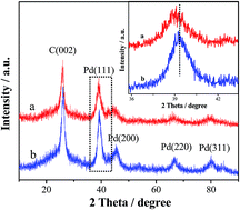
PdSn nanocatalysts supported on carbon nanotubes synthesized in deep eutectic solvents with high activity for formic acid electrooxidation

Rui-Xiang Wangab, You-Jun Fan*a, Zhi-Rong Lianga, Jun-Ming Zhanga, Zhi-You Zhoub and Shi-Gang Sun*b
aGuangxi Key Laboratory of Low Carbon Energy Materials, College of Chemistry and Pharmaceutical Sciences, Guangxi Normal University, Guilin 541004, China. E-mail: youjunfan@mailbox.gxnu.edu.cn; Fax: +86-773-2120958; Tel: +86-773-5846279
bState Key Laboratory of Physical Chemistry of Solid Surfaces, Department of Chemistry, College of Chemistry and Chemical Engineering, Xiamen University, Xiamen 361005, China. E-mail: sgsun@xmu.edu.cn; Fax: +86-592-2180181; Tel: +86-592-2180181

Received 20th April 2016 , Accepted 16th June 2016

First published on 16th June 2016


Abstract

Deep eutectic solvents (DESs) are being increasingly used in electrochemically controllable synthesis of functional nanomaterials because of their unique merits (e.g., high conductivity, wide electrochemical windows and environmental friendship). Herein, we report a novel strategy in DESs for the fabrication of multi-walled carbon nanotubes (MWCNTs)-supported Pd-based alloy nanostructures. Using a NaBH4 solvothermal reduction process in DESs, highly active PdSn alloy nanocatalysts supported on MWCNTs towards the formic acid oxidation (FAO) reaction were synthesized for the first time. The as-synthesized materials were characterized by X-ray diffraction (XRD), transmission electron microscopy (TEM), energy dispersive X-ray (EDX) spectroscopy, X-ray photoelectron spectroscopy (XPS) and electrochemical tests. The results demonstrate that the PdSn nanocluster structure with a rough surface provides a high density of catalytically active sites and thereby increases the electrochemically active surface area. There is a strong charge transfer interaction between Pd and Sn in the PdSn/MWCNT catalyst due to its high degree of alloying. The electrochemical studies indicate that the PdSn/MWCNT shows remarkably improved electrocatalytic performance towards FAO compared to Pd/MWCNT and commercial Pd/C catalysts. This study suggests an effective synthesis strategy for Pd-based electrocatalysts with high performance for DFAFCs applications.


1. Introduction

Direct formic acid fuel cells (DFAFCs) represent a prospective green power device for future energy conversion applications.1–3 Compared with direct methanol fuel cells, DFAFCs possess several advantages, including competitive energy density, high electromotive force (1.45 V), low fuel crossover and utilization of a safe fuel source.4,5 Pd- and Pt-based materials are the two anode catalysts most commonly used in DFAFCs.6 Compared to Pt, Pd has attracted considerable interest due to its greater availability and superior electrocatalytic activity at the initial stage of formic acid oxidation (FAO). It is widely accepted that FAO on Pd surfaces occurs readily through a direct dehydrogenation path to CO2 without significantly forming toxic COad intermediates that can be produced on Pt surfaces through the dehydration of formic acid.7,8 However, the FAO performance of monometallic Pd catalysts can be rapidly degraded by the dissolution of Pd species and the slow accumulation of intermediates under acidic operating conditions.9–11 Therefore, improvement of the catalytic activity and stability of Pd-based catalysts is of crucial importance in meeting the requirements of DFAFCs applications.

To improve the performance of Pd electrocatalysts in FAO, extensive efforts have been devoted to the synthesis of various Pd-based alloys containing a second transition metal, these alloys include PdPt,6,12 PdCo,13 PdAu,11,14 PdAg,15 PdCu,4,16 PdPb,17 and PdSn.18–21 Among these catalysts, the PdSn binary system has attracted considerable attention due to the electronic effect of Sn, which changes the electronic state of the Pd atoms, thereby decreasing the adsorption of poisonous intermediates (e.g., COad and COOHad) on the catalytic surface. For example, Liu et al.,19 using a microwave-assisted polyol process, prepared PdSn nanoparticles supported on carbon black (Vulcan XC-72) that showed increased FAO electrocatalytic activity. Tu et al. also reported the synthesis of a carbon-supported PdSn (PdSn/C) catalyst by a chemical reduction method with the aid of microwave radiation, this catalyst exhibited enhanced electrocatalytic performance for FAO.20 More recently, Sun et al. found that three-dimensional porous Pd–Sn intermetallics with network nanostructures can be fabricated using a one-step ethylene glycol-assisted hydrothermal method, and this material exhibited much higher electrocatalytic activity and stability for FAO than commercial Pd black.21 However, the PdSn catalysts described above were generally prepared in aqueous or ethylene glycol solutions, and the electrochemical performance of PdSn catalysts needs further enhancement.

Deep eutectic solvents (DESs), a novel class of solvents consisting of quaternary ammonium salts and hydrogen-bond donors (e.g., carboxylic acids, amides and polyols) that were first reported by Abbott and co-workers,22,23 have received intensive attention in electrocatalysis applications due to their remarkable physicochemical properties, which include high conductivity, thermostability, negligible vapor pressure and wide electrochemical potential windows.24–26 In particular, we have reported the electrochemically shape-controlled synthesis in DESs of concave THH Pt NCs enclosed by {910} high-index facets and Pt nanoflowers with single crystal petals, these NCs exhibited superior electrocatalytic activity and stability for ethanol oxidation compared to a commercial Pt black catalyst.27,28 More recently, Renjith et al. reported the electrodeposition preparation in DESs of Au@Pd core–shell nanoparticles with high catalytic performance for methanol oxidation.29 However, all of these catalytic materials were prepared by the electrochemical deposition route, which has some limitations according to the product output.30 In this paper, we report for the first time the chemical reduction synthesis in DESs of highly active PdSn alloy nanocatalysts supported on multi-walled carbon nanotubes (MWCNTs) for the FAO reaction. The size, morphology and structure of as-prepared materials were characterized by X-ray diffraction (XRD) and transmission electron microscopy (TEM). Their surface composition and chemical state were measured by energy dispersive X-ray (EDX) spectroscopy and X-ray photoelectron spectroscopy (XPS). The electrochemical performance of the samples was studied by cyclic voltammetry (CV) and chronoamperometry (CA) techniques. The results demonstrate that use of the DESs medium significantly changed the morphology and structure of the catalytic nanoparticles. The PdSn alloy nanoparticles of ca. 2.3 nm tend to agglomerate and form the characteristic nanoclusters along the MWCNT surface. Due to its nanocluster structure with a rough surface and to the strong electron interaction between Pd and Sn in the catalyst, the as-prepared PdSn/MWCNT exhibits enhanced catalytic activity and stability for FAO compared with Pd/MWCNT and commercial Pd/C catalysts.

2. Experimental

2.1. Materials

Pristine MWCNTs with diameters of 40–60 nm, lengths of 5–15 μm, and purity of 98% were purchased from Shenzhen Nanotech Port Co. Ltd. (Shenzhen, China). Nafion solution (5 wt%) was purchased from Sigma-Aldrich. Choline chloride [HOC2H4N(CH3)3Cl], urea, absolute ethanol, PdCl2, NaBH4, SnCl2, formic acid, sulfuric acid and nitric acid were purchased from Shanghai Chemical Reagent Co. Ltd., and the commercial Pd/C (10% Pd content) was obtained from Alfa Aesar. All of the reagents used were analytically pure and were used as received unless otherwise specified. The triple-distilled water was used for the preparation of all the aqueous solutions.

2.2. Synthesis of PdSn/MWCNT catalyst

Choline chloride/urea DESs were prepared according to a previously described method.27,28 The pristine MWCNTs were subjected to a traditional acid-oxidation treatment to increase their surface activity.31 The one-step synthesis of PdSn/MWCNT catalyst in DESs was conducted in terms of the following method: 10 mg of acid-oxidized MWCNTs was ultrasonicated in 20 mL DESs for 2 h. Then, 382 μL of 56.4 mM PdCl2/DESs and 42 μL of 49.7 mM SnCl2/DESs solution were added to the MWCNTs suspension, followed by ultrasonication for 1 h and magnetic stirring for 1 h. Next, 100 mg of NaBH4 was added to the system with continuous stirring for 10 min, and the mixture was transferred to a 25 mL Teflon-lined stainless steel autoclave. After solvothermal treatment at 150 °C for 12 h, the resulting solid was collected by centrifugation, washed repeatedly with triple-distilled water, and finally dried under vacuum at 60 °C for 12 h. As a comparison, an MWCNT-supported Pd catalyst (Pd/MWCNT) was prepared using a procedure similar to that described above.

2.3. Physical characterization

X-ray diffraction (XRD) measurements were carried out using a Rigaku D/MAX 2500 v/pc X-ray diffractometer with the Cu Kα radiation (λ = 1.5406 Å). A Physical Electronics PHI Quantum 2000 system with the Al Kα radiation was used for X-ray photoelectron spectroscopy (XPS) tests; all XPS data were corrected by the C 1s binding energy value (284.5 eV). The morphologies and structures of the samples were studied using a JEOL JEM-2100 high resolution transmission electron microscopy (HRTEM) operated at 200 kV. The composition of the catalysts was measured using energy dispersive X-ray (EDX) spectroscopy interfaced with the same TEM (JEM-2100). High-angle annular dark-field scanning transmission electron microscopy (HAADF-STEM) images and element mapping were obtained using an FEI Tecnai-F30 microscope. Noble metal content measurements of different samples were conducted using the IRIS Intrepid II XSP inductively coupled plasma-optical emission spectrophotometer (ICP-OES). In this work, the Pd contents of the PdSn/MWCNT and Pd/MWCNT samples were measured to be 10.53% and 15.35%, respectively. The ICP-OES analysis indicates that the atomic ratio of Pd and Sn in the PdSn/MWCNT is approximately 10[thin space (1/6-em)]:[thin space (1/6-em)]1, which is in good agreement with the stoichiometric ratio in the precursor solutions.

2.4. Electrochemical studies

Electrochemical studies were carried out on a CHI 660D electrochemical testing system by using a conventional three-electrode electrolytic cell. The working electrode was a catalyst-modified glass carbon (GC, Φ = 5 mm) electrode; it was prepared with reference to the previous method.31 As for the PdSn/MWCNT and Pd/MWCNT samples, the Pd content on different working electrodes was 7.9 and 11.5 μg cm−2, respectively. The counter electrode was a piece of Pt foil (1 cm2 area), and the reference electrode was a commercial saturated calomel electrode (SCE). All of the potentials in this study are referred to the SCE. All of the electrochemical experiments were performed at room temperature (approximately 25 °C). The electrocatalytic properties of catalysts for FAO were measured in 1.0 M HCOOH + 0.5 M H2SO4 solution. For CO stripping voltammetry, the working electrode was first bubbled with CO in 0.5 M H2SO4 solution for 15 min to allow saturated adsorption of CO while keeping the potential sweep in the range of −0.2–0.0 V. The dissolved CO in the solution was then removed by bubbling pure N2 for 20 min. Finally, the CO stripping voltammograms were recorded by oxidizing pre-adsorbed CO at 50 mV s−1. All of the currents in the electrochemical experiments were normalized with the Pd loading on the working electrode. Prior to each measurement, the electrolyte was degassed with pure N2 for 15 min, and a N2 flow was maintained over the electrolyte to impede the disturbance of oxygen in air.

3. Results and discussion

The XRD patterns shown in Fig. 1 permit analysis of the phase structure of PdSn/MWCNT and Pd/MWCNT samples. The diffraction peak that appears at about 26° in both curves is evidently due to the (002) crystal plane in the hexagonal structure of the MWCNTs.3,32 The other four diffraction peaks at 2θ = 40°, 47°, 68° and 82° are attributed to the (111), (200), (220) and (311) reflections of Pd, respectively; these represent the characteristic crystalline Pd face-centered cubic (fcc) phase.33,34 There are no diffraction signals of pure Sn or SnO in the XRD patterns, indicating that the PdSn nanoparticles have the prevailing fcc Pd crystal structure. It is noted that the diffraction peaks of Pd for the PdSn/MWCNT catalyst shift to a lower 2θ value than those of the Pd/MWCNT; this can be clearly observed in the expanded view of the Pd(111) reflections shown in the inset of Fig. 1. Obviously, because the atomic radius of Sn (0.141 nm) is larger than that of Pd (0.138 nm), the lower 2θ angle of the PdSn/MWCNT catalyst indicates the formation of a PdSn alloy structure. Moreover, the average crystallite sizes of the nanoparticles of both catalysts can be evaluated from the XRD patterns according to Scherrer's formula.6,35 The crystallite diameters of the PdSn/MWCNT and Pd/MWCNT catalysts thus obtained are approximately 2.3 nm and 4.1 nm, respectively, demonstrating that the addition of Sn significantly decreases the size of the catalytic nanoparticles. A similar phenomenon was also observed by Qin et al. and by Tu et al. in the analysis of synthesized Pd-based alloy nanoparticles.11,20
image file: c6ra10176c-f1.tif
Fig. 1 XRD patterns of PdSn/MWCNT (a) and Pd/MWCNT (b) catalysts. The inset is an expanded view of the (111) reflections.

The morphology, composition and structure of the as-obtained samples were characterized by TEM. Fig. 2 shows TEM images of the PdSn/MWCNT and Pd/MWCNT samples. In Fig. 2A and B, it can be seen that smaller PdSn alloy nanoparticles tend to agglomerate along the MWCNTs, forming a distinctive nanocluster structure with a rough surface. The Pd/MWCNT catalyst (Fig. 2C and D) forms a similar nanostructure along the MWCNTs, but this structure has a smooth surface compared to that of the PdSn/MWCNT. Notably, the coarse surface of the PdSn/MWCNT possesses abundant low-coordination atoms and produces an increase in its electrochemically active surface area (ECSA), which is very important to enhance the electrocatalytic performance of PdSn/MWCNT catalyst.


image file: c6ra10176c-f2.tif
Fig. 2 (A and B) TEM images of the PdSn/MWCNT catalyst; (C and D) TEM images of the Pd/MWCNT catalyst.

To obtain additional information about the PdSn/MWCNT catalyst, HRTEM and EDX characterizations were performed. As shown in Fig. 3A, the lattice spacing of 0.246 nm, 0.241 nm and 0.242 nm observed for PdSn/MWCNT can be indexed as the {111} crystalline planes of fcc Pd. The spacing of these planes is greater than that of pure Pd (0.223 nm), indicating expansion of the lattice upon substitution of Pd with Sn and the formation of PdSn alloys. It is worth noting that the PdSn/MWCNT catalyst exhibits the dominant {111} planes, which are less susceptible to oxidation and more practical for fuel cell applications.36 The EDX spectrum (Fig. 3B) of the PdSn/MWCNT catalyst displays the signals of C, O, Pd and Sn elements, confirming the deposition of PdSn nanostructures on the MWCNT surface. The HAADF-STEM mapping images reveal that both Pd and Sn are homogeneously distributed in the nanocluster structure (Fig. 3C), further suggesting the formation of a PdSn alloy structure.


image file: c6ra10176c-f3.tif
Fig. 3 HRTEM image (A), EDX spectrum (B), HAADF-STEM image and the corresponding elemental mapping (C) of the PdSn/MWCNT catalyst.

The composition of the catalytic surface was also investigated by XPS. Fig. 4A displays the XPS survey spectra for the PdSn/MWCNT and Pd/MWCNT samples. The peaks corresponding to C 1s (284.7 eV), O 1s (531.9 eV) and Pd 3d (339.5 eV) can be observed for both catalysts.3,35,37 It is noted that the Sn 3d (486.4 eV) signal is only observed in the spectrum for PdSn/MWCNT, a finding that supports the conclusion that the PdSn/MWCNT catalyst was successfully prepared. The N 1s (400.4 eV) signal seen in both spectra may originate from the DESs medium. In the case of the Sn 3d spectrum of PdSn/MWCNT (Fig. 4B), the deconvolution of its asymmetric photoemission produces two doublets, indicating two distinct oxidation states of Sn existed in the catalyst. The two dominant peaks at 485.2 eV (Sn 3d5/2) and 493.5 eV (Sn 3d3/2) originate from metallic Sn(0); the weak peaks at 486.8 eV (Sn 3d5/2) and 495.2 eV (Sn 3d3/2) are assigned to the oxidized species of Sn(II/IV).21,38 Moreover, the Pd 3d spectrum of the PdSn/MWCNT catalyst (Fig. 4C) splits into two peaks, one at a lower binding energy (Pd 3d5/2) and another at a higher binding energy (Pd 3d3/2). Each of these two peaks can be deconvoluted into two distinct Pd oxidation states, Pd(0) and Pd(II). The peaks at 334.7 eV (Pd 3d5/2) and 340.0 eV (Pd 3d3/2) are assigned to metallic Pd(0), the peaks at 335.3 eV (Pd 3d5/2) and 341.0 eV (Pd 3d3/2) are attributed to PdOads, and the peaks at 337.3 eV (Pd 3d5/2) and 342.9 eV (Pd 3d3/2) are assigned to PdO species.35,39,40 As for the Pd/MWCNT (Fig. 4D), the Pd 3d5/2 signal (335.0 eV) and the Pd 3d3/2 signal (340.3 eV) belong to the Pd(0) state, whereas the Pd 3d5/2 signal (335.9 eV) and the Pd 3d3/2 signal (341.4 eV) are ascribed to the PdOads, the Pd 3d5/2 signal (337.7 eV) and the Pd 3d3/2 signal (343.0 eV) are assigned to the PdO species. According to the relative areas of these signals, the percentages of metallic Pd(0) in the PdSn/MWCNT and Pd/MWCNT catalysts were calculated to be 76.8% and 78.2%, respectively. The fact that both the PdSn/MWCNT and the Pd/MWCNT catalysts contain a high percentage of Pd/Sn metallic species indicates that the Pd(II) and Sn(II) precursors were effectively reduced during the solvothermal reduction process in DESs. In addition, a small shift (0.3 eV) of the Pd peaks to lower binding energies is found in the PdSn/MWCNT sample, demonstrating strong charge transfer interactions from Sn to Pd atoms in the PdSn alloy nanostructure.18 The charge transfer interactions between Pd and Sn will obviously alter the electronic states of Pd atoms, thereby improving the electrocatalytic activity and stability of the PdSn/MWCNT for FAO.


image file: c6ra10176c-f4.tif
Fig. 4 (A) XPS survey spectra of PdSn/MWCNT (a) and Pd/MWCNT (b) samples; (B) Sn 3d spectrum of PdSn/MWCNT; (C) Pd 3d spectrum of PdSn/MWCNT; (D) Pd 3d spectrum of Pd/MWCNT.

The electrochemical characterization of the catalysts was conducted in 0.5 M H2SO4 aqueous solution by using the CV method. CO stripping voltammograms and the resulting CV curves of PdSn/MWCNT, Pd/MWCNT and commercial Pd/C catalysts are shown in Fig. 5. It is found that for all the samples, the hydrogen adsorption/desorption current in the stripping voltammograms is entirely restrained due to the saturated adsorption of CO species. After the oxidation of adsorbed CO (COad), the hydrogen adsorption/desorption current signals appear in the subsequent CV curves. The onset oxidation potential of COad on the PdSn/MWCNT (Fig. 5A) is shifted to a more negative value (0.51 V), whereas the corresponding potentials for the Pd/MWCNT (Fig. 5B) and the commercial Pd/C (Fig. 5C) catalysts are 0.61 V and 0.64 V, respectively, demonstrating the superior CO tolerance of PdSn/MWCNT compared to the Pd/MWCNT and Pd/C catalysts. In addition, the ECSA values of electrocatalysts reflect their intrinsic electrocatalytic activities, and the utilization ratios of noble metals are closely related to their dispersion and to the ECSA. Because hydrogen absorption into the bulk Pd lattice occurs during the CV characterization process, the real surface area of Pd-based catalysts cannot be calculated based on the hydrogen adsorption/desorption charge.41,42 Therefore, the COad oxidation charge (QCO) was used to evaluate the ECSA values of Pd-based electrocatalysts according to the following formula:43

image file: c6ra10176c-t1.tif


image file: c6ra10176c-f5.tif
Fig. 5 CO stripping curves of PdSn/MWCNT (A), Pd/MWCNT (B) and commercial Pd/C (C) in 0.5 M H2SO4 solution at 50 mV s−1.

In this formula, WPd represents the amount of Pd on the catalyst-modified electrode. The obtained ECSA values were 49.32, 30.63 and 140.02 m2 g−1 for the PtSn/MWCNT, Pd/MWCNT and Pd/C, respectively. The fact that the ECSA value of the PdSn/MWCNT is greater than that of the Pd/MWCNT catalyst may be attributed to the rough surface of the PdSn/MWCNT catalyst and the smaller PdSn crystallite size in the nanocluster structure. The ECSA value of commercial Pd/C is the largest of those of the three catalysts, most likely due to the greater dispersion of Pd nanoparticles on the carbon black support.

The electrocatalytic activities of the PdSn/MWCNT, Pd/MWCNT and commercial Pd/C toward FAO were evaluated by the CV method in 0.5 M H2SO4 aqueous solution containing 1.0 M HCOOH. As shown in Fig. 6, the FAO reactions on the three catalysts show CV characteristics similar to those reported by others.3,16,44 In the forward potential scan, an intense peak in the range of ca. 0.18–0.3 V and a weak peak at 0.6 V correspond to FAO via the direct dehydrogenation pathway and the oxidation of adsorbed CO-like intermediates, respectively. The maximum peak current density of FAO on the PdSn/MWCNT (curve a) in the forward scan is 2780.7 mA mgPd−1, 1.81 and 3.27 times higher, respectively, than the maximum peak current densities for the Pd/MWCNT (curve b, 1532.8 mA mgPd−1) and commercial Pd/C (curve c, 850.4 mA mgPd−1) catalysts. Notice that the mass electroactivity of the PdSn/MWCNT catalyst is also greater than that of other Pd-based catalysts reported previously, including carbon-supported PdSn nanoparticles (below 350 mA mgPd−1),19 flower-like Pd3Pb nanocrystals (1050 mA mgPd−1),45 PdNi/rGO composite (ca. 1000 mA mgPd−1),46 Pd–Co nanoassemblies (267.0 mA mgPd−1),47 and PdAg/Ti0.5Cr0.5N hybrid (975 mA mgPd−1).48 These results indicate that the prepared PdSn/MWCNT catalyst shows enhanced electrocatalytic activity for FAO compared to the Pd/MWCNT and Pd/C catalysts.


image file: c6ra10176c-f6.tif
Fig. 6 Cyclic voltammograms of PdSn/MWCNT (a), Pd/MWCNT (b) and commercial Pd/C (c) in 1.0 M HCOOH + 0.5 M H2SO4 solution obtained at 50 mV s−1.

The long-term electrocatalytic activity and durability of the three catalysts for FAO were further evaluated by chronoamperometry tests conducted in 0.5 M H2SO4 aqueous solution containing 1.0 M HCOOH at a potential of 0.1 V. As seen from Fig. 7, the current density of the FAO reaction on all three catalysts shows an initial rapid decay followed by a slower reduction. The initial current decay indicates the deactivation of the catalysts resulting from the adsorption of CO-like intermediate species.48 After the measurement of 7200 s, the stable current density of FAO on the PdSn/MWCNT catalyst is 93.4 mA mgPd−1 (curve a), still much higher than the current densities on the Pd/MWCNT (curve b, 51.6 mA mgPd−1) and Pd/C (curve c, 29.2 mA mgPd−1) catalysts. Moreover, the stable current density (7200 s) of the PdSn/MWCNT for FAO is 8.6% of its initial value (taking the current density at 10 s as the reference to avoid the effect of double-layer charging and hydrogen adsorption),49,50 higher than the corresponding values for the Pd/MWCNT (5.7%) and Pd/C (4.5%) catalysts. The results show that the PdSn/MWCNT possesses superior electrocatalytic activity and durability towards the FAO reaction. The significantly enhanced FAO performance of the PdSn/MWCNT catalyst apparently arises from its special nanocluster structure and from the addition of Sn. The nanocluster structure, with its rough surface, may provide a higher density of catalytically active sites such as edge, kink, corner and surface-stepped atoms. On the other hand, strong charge transfer interactions between Pd and Sn occur in the PdSn/MWCNT catalyst due to its high degree of alloying, and the strong interactions should be responsible for the enhanced FAO performance of the PdSn/MWCNT catalyst.


image file: c6ra10176c-f7.tif
Fig. 7 Chronoamperometric curves of PdSn/MWCNT (a), Pd/MWCNT (b) and commercial Pd/C (c) in 1.0 M HCOOH + 0.5 M H2SO4 solution at a potential of 0.1 V. The inset is the magnified picture of the boxed area.

4. Conclusions

The chemical reduction synthesis in DESs of highly active PdSn alloy nanocatalysts supported on MWCNTs for the FAO reaction is reported. XRD and TEM measurements of the structure of this catalyst indicate that PdSn nanoparticles of ca. 2.3 nm tend to agglomerate along the MWCNTs in DESs and to form a distinctive alloy nanostructure with a rough surface. XPS analysis confirms the strong charge transfer interaction between Pd and Sn in the PdSn/MWCNT catalyst. The results of electrochemical studies show that as prepared, PdSn/MWCNT possesses excellent electrocatalytic activity and durability towards FAO compared to the Pd/MWCNT and commercial Pd/C catalysts. This work is of significance for the design and fabrication of Pd-based electrocatalysts with high performance for DFAFCs applications.

Acknowledgements

This work was supported by the National Natural Science Foundation of China (21463007, 21321062, 21263002, and 21229301), the Guangxi Natural Science Foundation of China (2013GXNSFAA019024, 2014GXNSFFA118003), the Opening Foundation of the State Key Laboratory for Physical Chemistry of Solid Surface of Xiamen University (201305), the BAGUI Scholar Program (2014A001) and the Project of Talents Highland of Guangxi Province.

Notes and references

  1. M. A. Matin, J. H. Jang and Y. U. Kwon, J. Power Sources, 2014, 262, 356 CrossRef CAS.
  2. W. L. Qu, Z. B. Wang, Z. Z. Jiang, D. M. Gu and G. P. Yin, RSC Adv., 2012, 2, 344 RSC.
  3. Z. M. Cui, P. J. Kulesza, C. M. Li, W. Xing and S. P. Jiang, Int. J. Hydrogen Energy, 2011, 36, 8508 CrossRef CAS.
  4. S. Hu, L. Scudiero and S. Ha, Electrochim. Acta, 2012, 83, 354 CrossRef CAS.
  5. H. Meng, F. Y. Xie, J. Chen and P. K. Shen, J. Mater. Chem., 2011, 21, 11352 RSC.
  6. H. X. Zhang, C. Wang, J. Y. Wang, J. J. Zhai and W. B. Cai, J. Phys. Chem. C, 2010, 114, 6446 CrossRef CAS.
  7. M. Hiroto, O. Tatsuhiro, S. Gabor and O. Masatoshi, Phys. Chem. Chem. Phys., 2008, 10, 3662 RSC.
  8. M. Fayette, J. Nutariya, N. Vasiljevic and N. Dimitrov, ACS Catal., 2013, 3, 1709 CrossRef CAS.
  9. R. Wang, S. Liao and S. Ji, J. Power Sources, 2008, 180, 205 CrossRef CAS.
  10. R. Chenitz and J. P. Dodelet, J. Electrochem. Soc., 2010, 157, B1658 CrossRef CAS.
  11. Y. H. Qin, Y. Jiang, D. F. Niu, X. S. Zhang, X. G. Zhou, L. Niu and W. K. Yuan, J. Power Sources, 2012, 215, 130 CrossRef CAS.
  12. J. Y. Lee, D. H. Kwak, Y. W. Lee, S. Lee and K. W. Park, Phys. Chem. Chem. Phys., 2015, 17, 8642 RSC.
  13. S. F. Ho, A. Mendoza-Garcia, S. Guo, K. He, D. Su, S. Liu, O. Metin and S. Sun, Nanoscale, 2014, 6, 6970 RSC.
  14. T. Maiyalagan, X. Wang and A. Manthiram, RSC Adv., 2014, 4, 4028 RSC.
  15. Y. Lu and W. Chen, ACS Catal., 2012, 2, 84 CrossRef CAS.
  16. C. Xu, A. Liu, H. Qiu and Y. Liu, Electrochem. Commun., 2011, 13, 766 CrossRef CAS.
  17. B. D. Adams, R. M. Asmussen, C. K. Ostrom and A. C. Chen, J. Phys. Chem. C, 2014, 118, 29903 CrossRef CAS.
  18. Z. Zhang, J. Ge, L. Ma, J. Liao, T. Lu and W. Xing, Fuel Cells, 2009, 9, 114 CrossRef CAS.
  19. Z. Liu and X. Zhang, Electrochem. Commun., 2009, 11, 1667 CrossRef CAS.
  20. D. Tu, B. Wu, B. Wang, C. Deng and Y. Gao, Appl. Catal., B, 2011, 103, 163 CrossRef.
  21. D. Sun, L. Si, G. Fu, C. Liu, D. Sun, Y. Chen, Y. Tang and T. Lu, J. Power Sources, 2015, 280, 141 CrossRef CAS.
  22. A. P. Abbott, G. Capper, D. L. Davies, R. K. Rasheed and V. Tambyrajah, Chem. Commun., 2003, 70 RSC.
  23. A. P. Abbott, D. Boothby, G. Capper, D. L. Davies and R. K. Rasheed, J. Am. Chem. Soc., 2004, 126, 9142 CrossRef CAS PubMed.
  24. D. V. Wagle, H. Zhao and G. A. Baker, Acc. Chem. Res., 2014, 47, 2299 CrossRef CAS PubMed.
  25. H. G. Liao, Y. X. Jiang, Z. Y. Zhou, S. P. Chen and S. G. Sun, Angew. Chem., Int. Ed., 2008, 47, 9100 CrossRef CAS PubMed.
  26. L. N. Wu, Y. L. Tan, L. Wang, S. N. Sun, Z. Y. Qu, J. M. Zhang and Y. J. Fan, Microchim. Acta, 2015, 182, 1361 CrossRef CAS.
  27. L. Wei, Y. J. Fan, N. Tian, Z. Y. Zhou, X. Q. Zhao, B. W. Mao and S. G. Sun, J. Phys. Chem. C, 2012, 116, 2040 CrossRef CAS.
  28. L. Wei, Y. J. Fan, H. H. Wang, N. Tian, Z. Y. Zhou and S. G. Sun, Electrochim. Acta, 2012, 76, 468 CrossRef CAS.
  29. A. Renjith and V. Lakshminarayanan, J. Mater. Chem. A, 2015, 3, 3019 RSC.
  30. T. Yu, D. Y. Kim, H. Zhang and Y. N. Xia, Angew. Chem., Int. Ed., 2011, 50, 2773 CrossRef CAS PubMed.
  31. R. X. Wang, Y. J. Fan, L. Wang, L. N. Wu, S. N. Sun and S. G. Sun, J. Power Sources, 2015, 287, 341 CrossRef CAS.
  32. Y. Ren, S. Zhang and H. Li, Int. J. Hydrogen Energy, 2014, 39, 288 CrossRef CAS.
  33. C. Hsu, C. Huang, Y. Hao and F. Liu, Electrochem. Commun., 2012, 23, 133 CrossRef CAS.
  34. N. Cheng, H. Lv, W. Wang, S. Mu, M. Pan and F. Marken, J. Power Sources, 2010, 195, 7246 CrossRef CAS.
  35. J. Q. Zeng, S. N. Sun, J. P. Zhong, X. F. Li, R. X. Wang, L. N. Wu, L. Wang and Y. J. Fan, Int. J. Hydrogen Energy, 2014, 39, 15928 CrossRef CAS.
  36. V. Mazumder and S. Sun, J. Am. Chem. Soc., 2009, 131, 5488 CrossRef PubMed.
  37. R. K. Pandey and V. Lakshminarayanan, J. Phys. Chem. C, 2009, 113, 21596 CrossRef CAS.
  38. J. M. Jacob, P. G. Corradini, E. Antolini, N. A. Santos and J. Perez, Appl. Catal., B, 2015, 165, 176 CrossRef CAS.
  39. D. L. Wang, S. F. Lu, P. J. Kulesza, C. M. Li, R. D. Marco and S. P. Jiang, Phys. Chem. Chem. Phys., 2011, 13, 4400 RSC.
  40. I. G. Casella and M. Contursi, J. Electroanal. Chem., 2006, 588, 147 CrossRef CAS.
  41. X. M. Wang and Y. Y. Xia, Electrochim. Acta, 2009, 54, 7525 CrossRef CAS.
  42. G. Andreasen, A. Visintin, R. C. Salvarezza, W. E. Triaca and A. J. Arvia, Langmuir, 1999, 15, 1 CrossRef CAS.
  43. J. Liu, Z. Huang, K. Cai, H. Zhang, Z. Lu, T. Li, Y. Zuo and H. Han, Chem.–Eur. J., 2015, 21, 17779 CrossRef CAS PubMed.
  44. X. Zhao, J. Zhu, L. Liang, C. Liu, J. Liao and W. Xing, J. Power Sources, 2012, 210, 392 CrossRef CAS.
  45. R. Jana, U. Subbarao and S. C. Peter, J. Power Sources, 2016, 301, 160 CrossRef CAS.
  46. Y. She, Z. Lu, W. Fan, S. Jewella and M. K. H. Leung, J. Mater. Chem. A, 2014, 2, 3894 RSC.
  47. L. Zhang, L. Wan, Y. Ma, Y. Chen, Y. Zhou, Y. Tang and T. Lu, Appl. Catal., B, 2013, 138–139, 229 CrossRef CAS.
  48. Z. Cui, M. Yang and F. J. DiSalvo, ACS Nano, 2014, 8, 6106 CrossRef CAS PubMed.
  49. Y. Chen, G. Zhang, J. Ma, Y. Zhou, Y. Tang and T. Lu, Int. J. Hydrogen Energy, 2010, 35, 10109 CrossRef CAS.
  50. X. W. Yu and P. G. Pickup, J. Power Sources, 2009, 192, 279 CrossRef CAS.

This journal is © The Royal Society of Chemistry 2016
Click here to see how this site uses Cookies. View our privacy policy here.