A pre-lithiated phloroglucinol based 3D porous framework as a single ion conducting electrolyte for lithium ion batteries

Rupesh Rohana, Kapil Pareekac, Zhongxin Chena and Hansong Cheng*ab
aDepartment of Chemistry, National University of Singapore, 3 Science Drive 3, Singapore. E-mail: chghs2@gmail.com
bSustainable Energy Laboratory, Faculty of Materials Science and Chemistry, China University of Geosciences, 388, Lumo Road, Wuhan 430074, P. R. China
cCentre for Energy & Environment, Malaviya National Institute of Technology, JLN Marg, Jaipur – 302017, India

Received 10th April 2016 , Accepted 23rd May 2016

First published on 25th May 2016


Abstract

We report the design and synthesis of an inherently porous single ion conducting gel electrolyte made from a pre-lithiated phloroglucinol-terephthalaldehyde 3D framework for lithium ion batteries, adopting a “bottom-up” approach. The cationic transference number of the membrane obtained by blending the complex with PVDF–HFP followed by solution casting was found to be 0.86, close to unity. The mobile lithium ions shuttle through the low resistant pathways offered by the 3D network by virtue of its high porosity. The electrolyte offers a high ionic conductivity of 6.3 × 10⁻⁴ S cm−1 at room temperature (22 °C), comparable to the values of most gel polymer electrolytes. Furthermore, the electrolyte membrane displays high thermal stability and good mechanical strength. Coin cells assembled with the membrane perform well at both room temperature and 80 °C.

1. Introduction

Recent studies on dual-ion movement of conventional liquid electrolytes of small lithium salts for lithium ion batteries (LIBs) have raised serious concerns over battery performance associated with safety and efficiency.1–8 The movement of the anionic part of the electrolyte, which does not contribute significantly to battery operation, produces concentration polarization and high interfacial resistance and thus degrades battery performance.8–10 The concept of single ion conducting polymer electrolytes was proposed to resolve the issue on dual-ion movement.11–14 In this approach, the anionic species of the electrolyte are anchored in the polymer through chemical bonds and thus remain immobile in electrochemical processes, while the lithium-ions commute between electrodes. By restricting the anionic movement, the cationic transference number can be increased close to unity.3,8,15–18 Several single ion conducting electrolytes have been designed and synthesized successfully in the last few years.19–25 These electrolytes use polymer back bones to hook up the anionic moieties with a high degree of charge delocalization, which gives rise to poor charge pairing with Li ions and thus results in high cationic mobility in the polymer matrix.26–33 The Li ions shuttling between electrodes takes place via a hopping process in the solid state or through an organic solvent in a gel state.27,34–40

Swift movement of Li ions is essential for proper battery performance and thus low resistant pathways are required.41 It has been well demonstrated that for gel electrolyte batteries, an electrolyte membrane with appropriate porosity may offers much smoother pathways than a dense membrane for Li ion transport.42,43 In a recent study, we demonstrated how an electrolyte membrane with appropriate porosity enhances battery performance significantly by constructing macro/meso pores in the polymer via a templating method.10 Although techniques, such as cross-linking and phase inversion, can be utilized to generate the desired porosity,10,44–46 materials with intrinsic porosity and suitable capability for lithium ion transport would be highly beneficial for facile fabrication of porous membranes. Recently, porous compounds such as covalent organic framework (COF) and metal organic framework (MOF), which have been utilized as electrodes for Li based batteries,47–49 may be considered for porous electrolyte membrane preparation. However, a synthesized MOF based electrolyte for Li-ion batteries did not display any battery performance.50 Recently, we developed a porous framework based gel electrolyte, post modified with lithium, which performs successfully in a lithium ion battery.51 This development has laid a solid foundation for a new class of inherently porous single ion conducting electrolytes (SICEs), which differs significantly from the sp3 boron based and other polymer based single ion conducting electrolytes that have been reported to date in terms of molecular architecture.10,24,26–29,31,33 However, the ‘top-down’ synthetic approach, widely used in nano-technology,52 yielded a chemical composition of the resultant electrolyte severely deviating from the expected values, which eventually hampers the electrochemical performance of the material. Furthermore, the technique is only restricted to the selection of 3D assemblies that allow post-addition of lithium, which may result in poor material uniformity. Finally, the degree of lithiation might differ from surface to bulk, mainly attributed to the rigidness of the 3D structure. In contrast to this approach, an addition of lithiums to precursors before the construction of porous network, similar to the ‘bottom-up’ approach,53 is more beneficial for design of intrinsically porous SICEs. Because lithiation takes place at the very early stage of the synthesis, the approach may provide better control on porosity and higher uniformity of chemical composition throughout the material.54 In addition, a wide variety of precursors with tailored properties can also be explored for synthesis of polymer electrolytes.

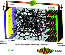
With this design concept in mind, we report synthesis and performance of a new naturally porous SICE pre-functionalized with lithium in this paper. A lithiated phloroglucinol and terephthalaldehyde were reacted together to form a phloroglucinol-terephthalaldehyde–lithium (PTF–Li) complex, which displays a three dimensional porous network. The complex was first blended with PVDF–HFP used as a binder in a solution and subsequently cast onto a Teflon dish to obtain a SICE membrane. A Li-ion coin cell was then assembled with the membrane and the performance of the cell was tested at room temperature as well as at an elevated temperature (Fig. 1).


image file: c6ra09215b-f1.tif
Fig. 1 Schematic description of a Li-ion battery with porous single ion conducting electrolyte.

2. Experimental

2.1 Materials

Phloroglucinol (Sigma-Aldrich), terephthalaldehyde (Sigma-Aldrich), butyllithium (Sigma-Aldrich), poly(vinylidene fluoride-co-hexafluoropropylene) (PVDF–HFP) (Mw – 400[thin space (1/6-em)]000 g mol−1) (Sigma-Aldrich), acetonitrile (Tedia), 1,4-dioxane (QREC), tetrahydrofuran (THF) (RCI labscan), dichloromethane (QREC). All chemicals were of an analytical grade and thus used without further purification.

2.2 Synthesis of phloroglucinol-terephthalaldehyde–lithium complex (PTF–Li)

PTF–Li was synthesized in two-steps as shown in Scheme 1. In the first step, 1 gram (8 mmol) of phloroglucinol and 15 ml of dry THF were transferred in a flame-dried three neck flask fitted with a dry ice-acetone Dewar and a magnetic stirring bar. The set up was kept under stirring in argon gas atmosphere for 30 min. Subsequently, 15 ml (0.008 mol) of butyllithium (1.6 M solution in hexane) reagent was injected drop-wise into the flask using a syringe. After stirring the reaction mixture at −78 °C for 12 h, hexane was removed under a reduced pressure to produce an off-white color powder of Li-modified-phloroglucinol. In the second step, Li-modified-phloroglucinol, terephthalaldehyde (1.61 g, 12 mmol) and 15 ml of 1,4-dioxane were charged into a Teflon lined autoclave in a glove box and stirred for two hours at 60 °C. The autoclave was placed in an oven at 200 °C for 4 days. After cooling to room temperature, a brown color solid was obtained and then washed with excess of THF, 1,4-dioxane, hexane, methanol and dichloromethane, respectively, at just below the boiling point of the respective solvents. The solid was dried in a tube furnace at 180 °C for 24 h with a yield of 65%.13 C CP-MAS (ppm): 51.5; 128.4; 166.3; 172.2 (Fig. S1 in ESI). Elemental analysis: for C15H6O8Li8, calculated: C, 48.73; H, 1.64; Li, 15.02%; found: C, 48.88; H, 4.04; Li, 4.83%.
image file: c6ra09215b-s1.tif
Scheme 1 Synthesis of PTF–Li complex.

2.3 PTF–Li/PVDF–HFP membrane preparation

PTF–Li and PVDF–HFP were weighed separately to mix in the ratios of 1[thin space (1/6-em)]:[thin space (1/6-em)]1, 2[thin space (1/6-em)]:[thin space (1/6-em)]1 and 1[thin space (1/6-em)]:[thin space (1/6-em)]2. The PVDF–HFP powder was dissolved in 6 ml of a DMF solvent at 60 °C for 1 h in a glass bottle fitted with a cap and a magnetic stirrer. Subsequently, a weighed amount of PTF–Li, corresponding to a given ratio, was added to the solution and stirred at 60 °C for 12 h. The mixture was then solution-cast onto a Teflon petri dish (6 cm diameter) and kept in an oven at 100 °C for 12 h to vaporize the DMF solvent. The formed membrane was dried further in vacuum at 100 °C for 24 h and then transferred to a glove box. The membrane was punched to obtain small circular films of 1.5 cm diameter and subsequently kept in an EC/PC (1[thin space (1/6-em)]:[thin space (1/6-em)]1 v/v) solution for soaking prior to be assembled in a battery cell and to be used for further characterizations.

3. Methods

The infrared spectra were recorded in the scanning frequency range of 4000–400 cm−1 on a Bio-Rad Excalibur FTIR Spectrometer. The thermal stability of the materials was measured by using a thermogravimetric analyzer (model TGA Q 50, TA Inc, USA) in a temperature range from room temperature to 1000 °C in a N2 gas atmosphere (gas flow rate: 60 cm3 min−1) at the heating rate of 10 °C min−1. The morphology of the synthesized materials and the fabricated membranes was studied using scanning electron microscopy (SEM) with a JEOL JSM-5200 Scanning Electron Microscope. A Baltec SCD050 platinum sputtering apparatus was used to sputter samples before the SEM analysis. The sputtering was performed under 5 × 10⁻² mbar pressure for 30 seconds with 30 mA current at room temperature. The N2 gas adsorption–desorption capacity of the samples was measured on a Micromeritics ASAP 2020 instrument. The samples were pre-activated at 100 °C, and ultra-pure helium gas (purity 99.9995%) was used to perform warm and cold free space corrections.

The ionic conductivity of the electrolyte membrane was calculated using electrochemical impedance spectroscopy with a Zahner potentiostat-galvanostat electrochemical workstation over the ac frequency range of 4 × 10⁶ to 1 Hz with the oscillating voltage of 5 mV. The electrolyte membrane was placed in a stainless steel device of 15 mm diameter inside a glove box and then heated at 80 °C to achieve a maximum contact between the membrane and the device surfaces. The Simulated Impedance Measurement (SIM) software, an built-in data fitting software on the Zahner electrochemical workstation, was used for raw data fitting. An Arbin BT-2000 battery tester was applied to investigate the performance of the electrolyte membranes assembled in CR 2025 battery coin cells with a LiFePO4 composite cathode and a Li metal anode. The composite cathode consists of LiFePO4 (75%), PVDF (10%), acetylene black (5%) and lithium bis(4-carboxy phenyl sulfonyl)imide (5%), which performs as a supporting electrolyte.

The lithium ion transference number of the electrolyte membranes was calculated with the method suggested by Evans and co-workers based on the combination of potentiostatic polarization and AC impedance.55 The method has been widely used for transport number calculations.1,10,27–29,31,33,51,56–59 The membranes were initially soaked in an EC[thin space (1/6-em)]:[thin space (1/6-em)]PC (1[thin space (1/6-em)]:[thin space (1/6-em)]1) (v/v) solution and subsequently sandwiched between two non-blocking lithium metal electrodes in a stainless steel device inside a glove box.19,60 The calculation was done using the following equation:

image file: c6ra09215b-t1.tif
where ΔV corresponds to the DC voltage applied on the cell. Io and Ro are the initial current and the bulk resistance before the polarization, respectively. Is and Rs are the steady state current and the bulk resistance after the DC polarization, respectively.

4. Results and discussion

4.1 Synthesis and characterization

The synthesis procedure of PTF–Li is analogous to the Bakelite synthesis; Bakelite is a thermosetting phenol formaldehyde resin.61 The lithiated phloroglucinol molecule undergoes an electrophilic substitution reaction readily.61 Each of the carbonyl groups of terephthalaldehyde combines with two phenyl rings of the lithiated phloroglucinol upon elimination of a water molecule. Therefore, one molecule of terephthalaldehyde can combine with four lithiated phloroglucinol assisted by the two carbonyl groups of the molecule; at the same time, a lithiated phloroglucinol molecule may combine with three terephthalaldehyde molecules (Scheme 1). The condensation polymerization reaction occurs at 200 °C in the presence of a dioxane solvent which provides a mild basic medium for the reaction.

The successful synthesis of the PTF–Li is confirmed by the solid state cross polarization magic angle spinning NMR spectroscopy (13C CP-MAS) and is well supported by the FTIR spectroscopy, elemental analysis and thermogravimetric analysis (TGA). For the 13C CP-MAS spectrum (Fig. S1), the peak at 51.5 ppm corresponds to the tertiary carbon formed upon condensation reaction. The highly intense peak at 128.4 ppm is assigned to the aromatic carbons while the peaks at 166.3 and 172.2 ppm may be attributed to the lithiated phenoxy carbon and the phenoxy carbon, respectively.61 In addition, the absence of a sharp peak near 195 ppm corresponding to the aldehydic carbon of terephthalaldehyde further confirms the occurrence of the condensation reaction.62

Fig. 2 displays the FTIR spectra of terephthalaldehyde, phloroglucinol and PTF–Li. The characteristic absorption bands of both phloroglucinol (1188 and 1008 cm−1) and terephthalaldehyde (2870 and 1690 cm−1 corresponding to the C–H stretch of CHO and the C[double bond, length as m-dash]O stretch, respectively) are absent in the PTF–Li spectrum, confirming the condensation reaction.61,63 The broad peak around 3400 cm−1 corresponds to the absorbed moisture. Finally, the elemental analysis also validates the successful synthesis of PTF–Li. The coherence between the found and the theoretical values of carbon content demonstrates the advantage of the pre-lithiation approach over the post-lithiation approach, which leads to poor material uniformity.51 The deviation for the found value of Li content from the expected value may be attributed to the vigorous washing, which might induce exchange of Li atoms with hydrogen atoms.


image file: c6ra09215b-f2.tif
Fig. 2 The FTIR spectra of terephthalaldehyde, phloroglucinol and the PTF–Li complex.

The TGA thermograms of terephthalaldehyde, phloroglucinol and the synthesized PTF–Li are shown in Fig. 3. With an initial 6% weight loss before 150 °C, corresponding to the evaporation of the absorbed moisture or trapped solvents in the pores, the PTF–Li shows a typical three step weight loss initiated after 340 °C, which is substantially higher than the degradation temperature of terephthalaldehyde (160 °C) and phloroglucinol (280 °C).61,62 The higher thermal stability of the PTF–Li complex further confirms the success of the poly-condensation reaction.51,64


image file: c6ra09215b-f3.tif
Fig. 3 The TGA thermograms of terephthalaldehyde, phloroglucinol and the PTF–Li complex (N2, 10 °C min−1, RT to 900 °C).

The porous nature of the PTF–Li complex was measured by nitrogen adsorption–desorption isotherms at 77 K and 1 bar (Fig. 4). The adsorption isotherm shows a low gas uptake at relatively low pressures and increases slowly in the middle region (Fig. 4a), which reflects the meso porous nature of the PTF–Li compound.65 The DFT pore size distribution curve confirms a wide range of nano-pores with the major pore size approximately around 3 nm (Fig. 4b); the porosity of PTF–Li is extrinsic and the pores are formed as the resultant of inefficient packing of the molecules coupled with a lack of topological self-complementarity.66,67


image file: c6ra09215b-f4.tif
Fig. 4 (a) The nitrogen adsorption–desorption isotherms at 77 K and 1 bar, and (b) the pore size distribution calculated from the nitrogen adsorption–desorption isotherms at 77 K using the DFT pore size analysis method.

The porosity of PTF–Li was examined with SEM (Fig. 5a). The compound exhibits a series of interconnected, loosely packed agglomerates, which facilitate facile transport of Li+ ions along with solvent molecules in electrolyte membranes.


image file: c6ra09215b-f5.tif
Fig. 5 The SEM images (a) PTF–Li and (b) the PVDF–HFP/PTF–Li membrane.

The high rigidity of the three dimensional structure of the PTF–Li complex makes the formation of a free standing membrane difficult. Instead, the material was blended with PVDF–HFP in various ratios to form electrolyte membranes. The membrane formed with 2[thin space (1/6-em)]:[thin space (1/6-em)]1 ratio of PVDF–HFP and PTF–Li displays reasonable mechanical strength and flexibility and thus was chosen for battery fabrication and further characterizations.

Fig. 5b depicts the SEM image of the PVDF–HFP/PTF–Li membrane. Since the PTF–Li molecules are dispersed very well in the PVDF–HFP matrix, the pores with diameters of few micrometers and above are largely unavailable except a few formed due to solvent evaporation. Shi and co-workers demonstrated that pores of less than 1 μm in diameter are most appropriate for lithium shuttling in batteries.45 We found that the absence of the large pores does not affect the ionic conductivity of the membrane significantly. The surface of the membrane is not very smooth mainly attributed to the poor solubility of PTF–Li in common organic solvents. Furthermore, the non-uniformity of the membrane is clearly evident in the image of the membrane (Fig. 6). Some tiny particles of PTF–Li are also visible on surfaces of the membrane. The roughness of the surface as well as the poor uniformity of the membrane may cause inferior interfacial resistance, which consequently may affect the battery performance adversely.


image file: c6ra09215b-f6.tif
Fig. 6 The PVDF–HFP/PTF–Li electrolyte membrane.

The mechanical strength of the membrane was assessed by determining its tensile strength, which was found to be 6.64 MPa with 17% elongation at break (Fig. 7). The strength of the membrane is well suited for use in a battery. We note that there is no explicit relationship between tensile strength and dendrite growth to the best of our knowledge. For example, commercially used polymer separators usually exhibit higher mechanical strength than gel polymer electrolytes; however, they are still prone to dendrite attack.68 In contrast, many gel polymer electrolytes, by virtue of impregnation of organic polymers in electrolyte solutions, were found to be more efficient than the commercial separators to suppress lithium dendrite growth.69–71


image file: c6ra09215b-f7.tif
Fig. 7 The tensile stress vs. tensile strain plot of the PVDF–HFP/PTF–Li electrolyte membrane.

4.2 Electrochemical properties

The Electrochemical Impedance Spectroscopy (EIS) study of the PVDF–HFP/PTF–Li membrane, soaked in an EC/PC solution, was performed in a temperature range from room temperature (22 °C) to 90 °C. The results are plotted in the Nyquist coordinates (Zvs. Z′′), where Z′ and Z′′ correspond to the real and the imaginary parts of the impedance, respectively (Fig. 8). The equivalent circuit used for the fitting is encompassed in the inset of the Fig. 8, where W, CPE, R1 and R2 represent the Warburg resistance, the constant phase element, the bulk resistance and the interfacial resistance, respectively.
image file: c6ra09215b-f8.tif
Fig. 8 The EIS plot of the PVDF–HFP/PTF–Li membrane at various temperatures. The inset is the corresponding equivalent circuit.

The ionic conductivity of the membrane, calculated from the EIS results, was found to be 6.3 × 10⁻⁴ S cm−1 at room temperature, comparable to the values of most of single ion conducting gel electrolytes reported to date.22,72–75 The exhibition of high ionic conductivity by the membrane is an interesting and noteworthy phenomenon, particularly, in view of the substantial structural difference between PTF–Li and other reported single ion conducting polymer electrolyte (SIPE) materials. For most SIPE materials, high ionic conductivity is attributed to the anionic portion of the electrolytes that resides in a strong electron-withdrawing environment in the polymer chains, which promotes separation of cationic and anionic charges and thus gives rise to high Li ion mobility. For the PTF–Li complex, although the anionic delocalization via highly substituted aromatic rings is not as pronounced as in the case found in most SIPEs, which, conceptually, should lead to lower Li ion mobility, the conductivity measured for the PTF–Li membrane is still on the same order of magnitude as for other SIPE materials. We speculate that the high ionic conductivity of the PTF–Li complex is likely due to the high micro-porosity of the electrolyte membrane to accommodate the selected organic solvent for Li ion transport.

The effect of temperature on the ionic conductivity of the PVDF–HFP/PTF–Li membrane was further examined and a plot between the log value of the ionic conductivity and the inverse of absolute temperature is depicted in Fig. 9. The graph displays a consonance with the characteristic Arrhenius curve in the testing temperature range from 90 °C to room temperature downwards. As expected, the measured conductivity increases linearly with temperature; however, it is not as steep as in the case of small molecular electrolytes or dual-ion based gel polymer electrolytes.76,77 The diminutive rise is attributed to the dependence of ion-transport on the mobility of polymer host at a given temperature on the basis of the free volume theory78 The highest measured conductivity at 90 °C for the membrane was found to be 1.4 × 10⁻³ S cm−1.


image file: c6ra09215b-f9.tif
Fig. 9 The Arrhenius plot of log(ionic conductivity) versus inverse absolute temperature.

The lithium-ion transference number (tLi+) of the PTF–Li membrane was calculated with the method proposed by Evans and co-workers by assembling a Li|PVDF–HFP/PTF–Li membrane|Li cell, where the membrane is sandwiched in between two non-blocking lithium metal electrodes.19,60 The parameters required for calculation of the tLi+ value are listed in Table 1. The transference number is 0.86 at room temperature, which reflects the single-ion conducting behaviour of the PTF–Li electrolyte as expected.

Table 1 List of variables and their values for calculation of lithium ion transference numbers (tLi+)
ΔV Io (μA) Is (μA) Ro (Ω) Rs (Ω)

image file: c6ra09215b-t2.tif

0.01 3.28 2.81 26.7 28.64 0.86


The width of electrochemical window of the PVDF–HFP/PTF–Li membrane was calculated by cyclic voltammetry using the Li|PVDF–HFP/PTF–Li membrane|stainless-steel cell. The results are shown in Fig. 10. The measurements were performed at both 25 °C and 80 °C between 0 and 5 V (versus Li+/Li) at the scan rate of 1 mV s−1. The PVDF–HFP/PTF–Li membrane was found electrochemically stable over 4.3 V at both room temperature and 80 °C, suggesting that the electrolyte is suited for battery applications.


image file: c6ra09215b-f10.tif
Fig. 10 The cyclic voltammetry of the PTF–Li/PVDF–HFP membrane at room temperature and 80 °C at the scan rate of 1 mV s−1.

The battery performance of the PVDF–HFP/PTF–Li membrane was evaluated by assembling a coin cell using LiFePO4 as the cathode and a lithium foil as the anode. In Fig. 11, the voltage profile of the battery cell Li|PVDF–HFP/PTF–Li membrane (EC/PC)|LiFePO4 as a function of its charge and discharge capacities for both room temperature and 80 °C is shown. The initial discharge capacities of the cell are 161 and 165 mA h g−1 at room temperature and 80 °C, respectively, at C/10 rate.18,22,23 Fig. 12 displays the discharge capacity curve vs. cycle number of the cell. The discharge capacity of the cell at room temperature ranges between 161 and 168 mA h g−1 at C/10 and between 159 and 151 mA h g−1 at C/5. In comparison, at 80 °C and the same C-rate, the discharge capacity varies in the range from 165 to 161 mA h g−1 at C/10 and from 157 to 159 mA h g−1. Although the discharge capacities shown by the battery cell at both temperatures are reasonable, the fluctuation in the measured discharge capacities during cycles is a major drawback of the membrane. The fluctuation is mainly attributed to the unevenness of the membrane surface, which leads to inferior interfacial resistance.


image file: c6ra09215b-f11.tif
Fig. 11 The charge and discharge profiles of the Li|PVDF–HFP/PTF–Li membrane (EC/PC)|LiFePO4 coin cell obtained at 80 °C for C/10 and C/5 rates.

image file: c6ra09215b-f12.tif
Fig. 12 The discharge capacity vs. cycle number of the Li|PVDF–HFP/PTF–Li membrane (EC/PC)|LiFePO4 coin cell, at room temperature and 80 °C for C/10 and C/5 rates.

5. Conclusion

We presented a “bottom-up” synthetic approach to construction of 3D porous network compounds as electrolytes of lithium-ion batteries via pre-lithiation of precursors and demonstrate the significant advantages of the method over the “top-down” approach via lithiation of post-polymerization. A 3D porous network complex, phloroglucinol-terephthalaldehyde–lithium (PTF–Li), was presented as a single ion conducting electrolyte material. Membranes of the compound blended with PVDF–HFP were fabricated via a solution cast method. The inherent porosity of the material offers low resistant pathways for Li-ion transport that result in the ionic conductivity on the order of 10−4 S cm−1 at room temperature, comparable to the value of most single ion conducting gel polymeric electrolytes. The PTF–Li complex displays high thermal stability at least up to 340 °C. The electrochemical stability of the membrane was found to be 4.3 V at room temperature and 80 °C.

The low solubility of PTF–Li in typical organic solvents causes unevenness of the membrane surfaces, which was found to hamper the battery performance. The present study suggests that pre-lithiated compounds with an inherent porous network potentially may serve as single ion conducting electrolytes with the essential attributes. A judicious selection of an organic solvent to enhance the solubility of these materials is important in order to fabricate smooth electrolyte membranes to improve electrolyte–electrode interfacial resistance and to ensure good battery performance.

Acknowledgements

The authors gratefully acknowledge support of a Start-up grant from NUS, a POC grant from National Research Foundation of Singapore, Singapore-Peking-Oxford Research Enterprise (SPORE), a Tier 1 grant from Singapore Ministry of Education, a DSTA grant and the National Natural Science Foundation of China (No. 21233006 and 21473164).

References

  1. R. Rohan, K. Pareek, Z. Chen, W. Cai, Y. Zhang, G. Xu, Z. Gao and H. Cheng, J. Mater. Chem. A, 2015, 3, 20267–20276 CAS.
  2. C. Brissot, M. Rosso, J. N. Chazalviel and S. Lascaud, J. Power Sources, 1999, 81–82, 925–929 CrossRef CAS.
  3. J. N. Chazalviel, Phys. Rev. A, 1990, 42, 7355–7367 CrossRef CAS.
  4. G. Sandí, K. A. Carrado, H. Joachin, W. Lu and J. Prakash, J. Power Sources, 2003, 119–121, 492–496 CrossRef.
  5. K. Xu, Chem. Rev., 2014, 114, 11503–11618 CrossRef CAS PubMed.
  6. J. M. Tarascon and M. Armand, Nature, 2001, 414, 359–367 CrossRef CAS PubMed.
  7. S. Feng, D. Shi, F. Liu, L. Zheng, J. Nie, W. Feng, X. Huang, M. Armand and Z. Zhou, Electrochim. Acta, 2013, 93, 254–263 CrossRef CAS.
  8. K. Xu, Chem. Rev., 2004, 104, 4303–4418 CrossRef CAS PubMed.
  9. X. G. Sun, C. L. Reeder and J. B. Kerr, Macromolecules, 2004, 37, 2219–2227 CrossRef CAS.
  10. R. Rohan, Y. Sun, W. Cai, K. Pareek, Y. Zhang, G. Xu and H. Cheng, J. Mater. Chem. A, 2014, 2, 2960–2967 CAS.
  11. L. C. Hardy and D. F. Shriver, J. Am. Chem. Soc., 1985, 107, 3823–3828 CrossRef CAS.
  12. M. Doyle, T. F. Fuller and J. Newman, Electrochim. Acta, 1994, 39, 2073–2081 CrossRef CAS.
  13. B. K. Mandal, C. J. Walsh, T. Sooksimuang, S. J. Behroozi, S.-g. Kim, Y.-T. Kim, E. S. Smotkin, R. Filler and C. Castro, Chem. Mater., 2000, 12, 6–8 CrossRef CAS.
  14. Y. Zhang, W. Cai, R. Rupesh, M. Pan, Y. Liu, X. Liu, C. Li, Y. Sun and H. Cheng, J. Power Sources, 2016, 306, 152–161 CrossRef CAS.
  15. P. G. Bruce, S. A. Freunberger, L. J. Hardwick and J.-M. Tarascon, Nat. Mater., 2012, 11, 19–29 CrossRef CAS PubMed.
  16. P. G. Bruce, B. Scrosati and J.-M. Tarascon, Angew. Chem., Int. Ed., 2008, 47, 2930–2946 CrossRef CAS PubMed.
  17. P. G. Bruce and C. A. Vincent, J. Chem. Soc., Faraday Trans., 1993, 89, 3187–3203 RSC.
  18. R. Bouchet, S. Maria, R. Meziane, A. Aboulaich, L. Lienafa, J.-P. Bonnet, T. N. T. Phan, D. Bertin, D. Gigmes, D. Devaux, R. Denoyel and M. Armand, Nat. Mater., 2013, 12, 452–457 CrossRef CAS PubMed.
  19. S. Feng, D. Shi, F. Liu, L. Zheng, J. Nie, W. Feng, X. Huang, M. Armand and Z. Zhou, Electrochim. Acta, 2013, 93, 254–263 CrossRef CAS.
  20. R. Meziane, J.-P. Bonnet, M. Courty, K. Djellab and M. Armand, Electrochim. Acta, 2011, 57, 14–19 CrossRef CAS.
  21. D. Golodnitsky, 2009, 5, 112–128.
  22. X.-G. Sun and J. B. Kerr, Macromolecules, 2005, 39, 362–372 CrossRef.
  23. X. Wang, Z. Liu, C. Zhang, Q. Kong, J. Yao, P. Han, W. Jiang, H. Xu and G. Cui, Electrochim. Acta, 2013, 92, 132–138 CrossRef CAS.
  24. Y. Zhang, G. Xu, Y. Sun, B. Han, W. T. Teguh Budiono, Z. Chen, R. Rohan and H. Cheng, RSC Adv., 2013, 3, 14934–14937 RSC.
  25. W. Cai, Y. Zhang, J. Li, Y. Sun and H. Cheng, ChemSusChem, 2014, 7, 1063–1067 CrossRef CAS PubMed.
  26. R. Rohan, Y. Sun, W. Cai, Y. Zhang, K. Pareek, G. Xu and H. Cheng, Solid State Ionics, 2014, 268, 294–299 CrossRef CAS.
  27. Y. Sun, R. Rohan, W. Cai, X. Wan, K. Pareek, A. Lin, Z. Yunfeng and H. Cheng, Energy Technol., 2014, 2, 698–704 CrossRef CAS.
  28. G. Xu, Y. Sun, R. Rohan, Y. Zhang, W. Cai and H. Cheng, J. Mater. Sci., 2014, 49, 6111–6117 CrossRef CAS.
  29. G. Xu, Y. Zhang, R. Rohan, W. Cai and H. Cheng, Electrochim. Acta, 2014, 139, 264–269 CrossRef CAS.
  30. Y. Zhang, C. A. Lim, W. Cai, R. Rohan, G. Xu, Y. Sun and H. Cheng, RSC Adv., 2014, 4, 43857–43864 RSC.
  31. Y. Zhang, R. Rohan, W. Cai, G. Xu, Y. Sun, A. Lin and H. Cheng, ACS Appl. Mater. Interfaces, 2014, 6, 17534–17542 CAS.
  32. Y. Zhang, R. Rohan, Y. Sun, W. Cai, G. Xu, A. Lin and H. Cheng, RSC Adv., 2014, 4, 21163–21170 RSC.
  33. Y. Zhang, Y. Sun, G. Xu, W. Cai, R. Rohan, A. Lin and H. Cheng, Energy Technol., 2014, 2, 643–650 CrossRef CAS.
  34. Advances in Lithium-Ion Batteries, ed. W. A. van Schalkwijik and Bruno Scrosati, Kluwer Academic Publishers, 2002 Search PubMed.
  35. K.-J. Lin, K. Li and J. K. Maranas, RSC Adv., 2013, 3, 1564–1571 RSC.
  36. R. C. Agrawal and G. P. Pandey, J. Phys. D: Appl. Phys., 2008, 41, 223001 CrossRef.
  37. A. Manuel Stephan, Eur. Polym. J., 2006, 42, 21–42 CrossRef CAS.
  38. C. Liao, X.-G. Sun and S. Dai, Electrochim. Acta, 2013, 87, 889–894 CrossRef CAS.
  39. X.-G. Sun, J. B. Kerr, C. L. Reeder, G. Liu and Y. Han, Macromolecules, 2004, 37, 5133–5135 CrossRef CAS.
  40. X.-G. Sun, C. L. Reeder and J. B. Kerr, Macromolecules, 2004, 37, 2219–2227 CrossRef CAS.
  41. M. Park, X. Zhang, M. Chung, G. B. Less and A. M. Sastry, J. Power Sources, 2010, 195, 7904–7929 CrossRef CAS.
  42. T.-H. Cho, M. Tanaka, H. Onishi, Y. Kondo, T. Nakamura, H. Yamazaki, S. Tanase and T. Sakai, J. Power Sources, 2008, 181, 155–160 CrossRef CAS.
  43. Y. Liang, L. Ji, B. Guo, Z. Lin, Y. Yao, Y. Li, M. Alcoutlabi, Y. Qiu and X. Zhang, J. Power Sources, 2011, 196, 436–441 CrossRef CAS.
  44. C. N. Walker, C. Versek, M. Touminen and G. N. Tew, ACS Macro Lett., 2012, 1, 737–741 CrossRef CAS.
  45. Q. Shi, M. Yu, X. Zhou, Y. Yan and C. Wan, J. Power Sources, 2002, 103, 286–292 CrossRef CAS.
  46. M. Osińska, M. Walkowiak, A. Zalewska and T. Jesionowski, J. Membr. Sci., 2009, 326, 582–588 CrossRef.
  47. A. Banerjee, K. K. Upadhyay, D. Puthusseri, V. Aravindan, S. Madhavi and S. Ogale, Nanoscale, 2014, 6, 4387–4394 RSC.
  48. S.-L. Li and Q. Xu, Energy Environ. Sci., 2013, 6, 1656–1683 CAS.
  49. D. Wu, Z. Guo, X. Yin, Q. Pang, B. Tu, L. Zhang, Y.-G. Wang and Q. Li, Adv. Mater., 2014, 26, 3258–3262 CrossRef CAS PubMed.
  50. B. M. Wiers, M.-L. Foo, N. P. Balsara and J. R. Long, J. Am. Chem. Soc., 2011, 133, 14522–14525 CrossRef CAS PubMed.
  51. R. Rohan, K. Pareek, W. Cai, Y. Zhang, G. Xu, Z. Chen, Z. Gao, D. Zhao and H. Cheng, J. Mater. Chem. A, 2015, 3, 5132–5139 CAS.
  52. Y. Wang and Y. Xia, Nano Lett., 2004, 4, 2047–2050 CrossRef CAS.
  53. V. Balzani, A. Credi and M. Venturi, Chem.–Eur. J., 2002, 8, 5524–5532 CrossRef CAS.
  54. K. Pareek, Q. Zhang, R. Rohan, G. Xu and H. Cheng, Adv. Mater. Interfaces, 2014, 1(9) DOI:10.1002/admi.201400107.
  55. J. Evans, C. A. Vincent and P. G. Bruce, Polymer, 1987, 28, 2324–2328 CrossRef CAS.
  56. L. Wang, N. Li, X. He, C. Wan and C. Jiang, Electrochim. Acta, 2012, 68, 214–219 CrossRef CAS.
  57. Q. Ma, H. Zhang, C. Zhou, L. Zheng, P. Cheng, J. Nie, W. Feng, Y.-S. Hu, H. Li, X. Huang, L. Chen, M. Armand and Z. Zhou, Angew. Chem., Int. Ed., 2016, 55, 2521–2525 CrossRef CAS PubMed.
  58. B. Qin, Z. Liu, J. Zheng, P. Hu, G. Ding, C. Zhang, J. Zhao, D. Kong and G. Cui, J. Mater. Chem. A, 2015, 3, 7773–7779 CAS.
  59. Y. Zhang, W. Cai, R. Rohan, M. Pan, Y. Liu, X. Liu, C. Li, Y. Sun and H. Cheng, J. Power Sources, 2016, 306, 152–161 CrossRef CAS.
  60. A. Ghosh, C. Wang and P. Kofinas, J. Electrochem. Soc., 2010, 157, A846–A849 CrossRef CAS.
  61. A. P. Katsoulidis and M. G. Kanatzidis, Chem. Mater., 2011, 23, 1818–1824 CrossRef CAS.
  62. J. Wang, Y. Masui and M. Onaka, Polym. Chem., 2012, 3, 865–867 RSC.
  63. L. Liu, P.-Z. Li, L. Zhu, R. Zou and Y. Zhao, Polymer, 2013, 54, 596–600 CrossRef CAS.
  64. K. Pareek, Q. Zhang, R. Rohan and H. Cheng, J. Mater. Chem. A, 2014, 2, 13534–13540 CAS.
  65. G. Yang, H. Han, C. Du, Z. Luo and Y. Wang, Polymer, 2010, 51, 6193–6202 CrossRef CAS.
  66. J. R. Holst, A. Trewin and A. I. Cooper, Nat. Chem., 2010, 2, 915–920 CrossRef CAS PubMed.
  67. K. Pareek, Q. Zhang, R. Rohan, Z. Yunfeng and H. Cheng, RSC Adv., 2014, 4, 33905–33910 RSC.
  68. H. Wu, D. Zhuo, D. Kong and Y. Cui, Nat. Commun., 2014, 5, 5193 CrossRef CAS PubMed.
  69. Y.-S. Lee, J. H. Lee, J.-A. Choi, W. Y. Yoon and D.-W. Kim, Adv. Funct. Mater., 2013, 23, 1019–1027 CrossRef CAS.
  70. W.-K. Shin, A. G. Kannan and D.-W. Kim, ACS Appl. Mater. Interfaces, 2015, 7, 23700–23707 CAS.
  71. T. Tatsuma, M. Taguchi and N. Oyama, Electrochim. Acta, 2001, 46, 1201–1205 CrossRef CAS.
  72. Y. S. Zhu, X. J. Wang, Y. Y. Hou, X. W. Gao, L. L. Liu, Y. P. Wu and M. Shimizu, Electrochim. Acta, 2013, 87, 113–118 CrossRef CAS.
  73. M. Watanabe, Y. Suzuki and A. Nishimoto, Electrochim. Acta, 2000, 45, 1187–1192 CrossRef CAS.
  74. L.-Y. Tian, X.-B. Huang and X.-Z. Tang, Eur. Polym. J., 2004, 40, 735–742 CrossRef CAS.
  75. X. Wang, Z. Liu, Q. Kong, W. Jiang, J. Yao, C. Zhang and G. Cui, Solid State Ionics, 2014, 262, 747–753 CrossRef CAS.
  76. J. Jiang, D. Gao, Z. Li and G. Su, React. Funct. Polym., 2006, 66, 1141–1148 CrossRef CAS.
  77. A. M. Voice, J. P. Southall, V. Rogers, K. H. Matthews, G. R. Davies, J. E. McIntyre and I. M. Ward, Polymer, 1994, 35, 3363 CrossRef CAS.
  78. O. E. Geiculescu, J. Yang, S. Zhou, G. Shafer, Y. Xie, J. Albright, S. E. Creager, W. T. Pennington and D. D. DesMarteau, J. Electrochem. Soc., 2004, 151, A1363–A1368 CrossRef CAS.

Footnote

Electronic supplementary information (ESI) available. See DOI: 10.1039/c6ra09215b

This journal is © The Royal Society of Chemistry 2016
Click here to see how this site uses Cookies. View our privacy policy here.