
 Open Access Article
 This Open Access Article is licensed under a
 Creative Commons Attribution 3.0 Unported Licence
Facile design of plant-oil-infused fine surface asperity for transparent blood-repelling endoscope lens†
Sachiko Nishiokaa,
Mizuki Tenjimbayashia,
Kengo Manabea,
Takeshi Matsubayashia,
Ken Suwabea,
Kosuke Tsukadab and
Seimei Shiratori*a
aDepartment of Integrated Design Engineering, Faculty of Science and Technology, Keio University, 3-14-1 Hiyoshi, Kohoku-ku, Yokohama, Kanagawa 223-8522, Japan. E-mail: shiratori@appi.keio.ac.jp
bDepartment of Fundamental Science and Technology, Faculty of Science and Technology, Keio University, 3-14-1 Hiyoshi, Kohoku-ku, Yokohama, Kanagawa 223-8522, Japan
First published on 9th May 2016
Abstract
Minimally invasive medical operations, especially endoscope operations, have attracted much attention and play a major role in modern medicine. Endoscope operations are superior to decrease incisions, enabling good post-operation progress. However, during its implementation, blood adheres to the lens of the endoscope, resulting in obstructed vision. This prolongs the operation time and causes the patient to gain weight. Hence, we developed a blood-repelling and transparent material for coating the surface of an endoscope lens. The coating material was produced from plant oil and a rough material for trapping the oil. Edible plant oil was particularly used to enable application to medical devices. A fine surface asperity was achieved by a one-dip treatment, which also enhanced the capillary force and durability of the oil under a water shower. The application of the developed coating material to an endoscope lens in an animal experiment enabled the effective repulsion of blood and other body fluids, the maintenance of a clear vision, and high transmittance. The developed coating material promises to contribute to the achievement of antifouling surfaces in medical devices.
Introduction
Minimally invasive medical operations have attracted increasing attention over the last several years, especially with regard to enhancing the quality of life (QOL) of surgical patients. Surgeons have developed and utilized diverse techniques and medical equipment for operating and examining the human body with less injury to the patients compared to open surgery.1–3 This has contributed to improving the QOL of patients.4–6 Endoscopes are often used for internal inspection of the human body, for example, to locate and operate tumors without laparotomy, which is the surgical procedure of making a large incision in the abdomen. The use of an endoscope not only reduces the size of the required incision, but also enables quick post-surgery recovery.3,7,8 However, the in vivo use of an endoscope suffers from the problem of adhesion of blood and other body fluids to the surface of the endoscope lens, resulting in obstructed vision.9 The current method for removing blood from the endoscope lens involves the withdrawal of the lens from the body to wipe off the blood, or the direction of a flow of washing water towards the contaminated lens. This, however, prolongs the surgery time, and the inclusion of a washing device necessitates the difficult task of producing a very thin endoscope.10In view of the foregoing, the idea has been conceived of applying a transparent antibiofouling and biocompatible coating to the endoscope lens to maintain clear vision during surgery. Previous studies to develop antibiofouling surfaces have considered the use of chemical treatment to produce superhydrophobic surfaces. This has been inspired by the lotus leaf, from which contacting liquids roll off in the form of spherical droplets.11,12 However, the structure of a superhydrophobic surface causes low mechanical durability and optical transparency, which limit the application of such surfaces.13–15 To overcome these drawbacks of a superhydrophobic surface, Aizenberg et al. proposed a slippery liquid-infused porous surface (SLIPS), which was inspired by the capture mechanism of the pitcher plant.16 A SLIPS is fabricated by impregnating a microstructured rough solid with a lubricant to repel a liquid that is immiscible with the lubricant.
SLIPSs have many potential applications owing to their additional features of transparency and frictional durability. Various studies on SLIPSs have investigated their use for purposes such as anti-icing,17,18 anticorrosion,19 antibiofouling,20–22 production of medical devices,23,24 condensation,25 and manipulation of liquid droplets.26 The employed lubricant determines the feasible application of the SLIPS. Previous works have considered and evaluated the effectiveness of lubricants such as a fluorinated lubricants,16,20,22 silicone oil,27 ferrofluid,26 plant oil,28 and ionic liquids.29 The diverse characteristics of the applicable lubricants enable a broad range of applications.
Despite these significant potentials, the achievement of a stable repellency in a SLIPS requires the combination of, for example, a fluorinated lubricant and a rough fluorinated microstructured solid to minimize the total interfacial tension. However, fluorinated materials are toxic, especially to the human body, and this has limited the application of SLIPSs in the medical field.30,31 There has thus been the challenge of developing a fluorine-free SLIPS with high transparency and stable repellency.
Precise control of the solid structure is required for the production of a fluorine-free SLIPS. Several methods for fabricating a rough-structured solid have been studied. Examples include the use of PDMS to mold the structure,21 photolithography,32,33 the breath figure method,34 the boehmite procedure,35 the spray method,11,36,37 and laser treatment.38 However, these methods are time-consuming and involve the use of a complex design of a rough “nano-to-micro-scale hybrid” surface to control the liquid/lubricant/solid interfacial tensions.
In this paper, we report the facile development of a fluorine-free SLIPS composed of a hydrophobic silica nanoparticle self-assembled underlayer impregnated with lubricant oil. Edible and eco-friendly plant oil was used as the lubricant. The use of fluorine-free materials also reduced the cost of producing the SLIPS (to about 130 ¢ per m2). The underlayer was easily produced by one-step coating of the self-assembled hydrophobic silica nanoparticles to form the nano-to-micro-scale hybrid rough surface. The rough surface was then used to trap the plant oil. This structure enables the lubricant to be retained under flowing water. The fabrication method also enables easy control of the surface morphology and allows selectivity in the choice of the substrate to enhance the antifouling ability. The oleophilic property of the developed underlayer enables stable retention of the plant oil, which is biocompatible and harmless to both nature and the human body. Blood and other liquids with differing pH values were repelled by the plant oil SLIPS, confirming the antifouling properties. We also performed an experiment in which an endoscope with a lens coated with the plant oil SLIPS was used to observe the inside of a mouse animal. The coat was found to prevent the adherence of body fluids to the lens, thus maintaining clear vision under pressure.
Experimental
Materials
Nanoparticles (of diameter = 40 nm), (AEROSIL Co.), tetraethyl orthosilicate (TEOS) (Wako Pure Chemical Industries, Ltd.), decyltrimethoxysilane (DTMS) (Shinetsu Kagaku Kogyo Co.), and 95%-pure ethanol (purity = 95%, Kanto Chemical Co.) were used to fabricate the underlayer of the SLIPS. Ultrapure water (Aquarius GS-500 CPW, Advantec, Japan) and an HCl solution (Kanto Chemical Co.) were used as catalysts for the sol–gel reaction. Sesame oil (with a surface tension = of 33.8 mN m−1, (Kadoya Sesame Mills) was used as the lubricant oil. Glass, while glass (76 × 26 × 1.0 mm), with a refractive index = of 1.52, (Matsunami Glass Industries, Ltd., Kishiwada, Japan) and wrap films (Asahi Kasei Co.) were respectively used as to produce the hard and soft-film polymer substrates. The glass substrates were cleaned for 3 min in a solution comprising KOH (Junsei Chemical Co.), ultrapure water, and 99.7%-pure isopropyl alcohol (IPA) (purity = 99.7%, Kanto Chemical Co.), and then rinsed thoroughly with ultrapure water before use.Preparation of methyl group modified nanoparticle solution
The typical procedure involved dispersion of 2.4 g of silica nanoparticles in 30 g of ethanol under magnetic stirring at room temperature for 30 min. TEOS (1 g) and DTMS (0.2 g) were then added to the dispersed silica solution and the stirring continued for 10 min. HCl (50 μL) and pure water (0.25 g) were subsequently added and the stirring was continued overnight. In the morning, the DTMS-modified silica nanoparticles were obtained in the form of an ethanol dispersion.Formation of rough underlayer and lubricant layer
The glass substrates were coated with the methyl group modified silica nanoparticle solution by the dip coating method. The typical procedure involved the cleaning of each substrate with a KOH solution comprising KOH (4.0 g), IPA (240 g), and ultrapure water (160 g). The cleaned substrates were then dipped into the silica solution for 10 s and then withdrawn. The dipping was done at a constant speed of 3.3 mm s−1. After the dip-coating, the substrates were heated at 150 °C for 1 h. This resulted in the formation of nanoporous structures on the substrates, thus completing the fabrication of the underlayer. Excess plant oil was thereafter infused into the nanopores on the underlayer to form a liquid lubricant layer. The excess oil was subsequently removed by positioning the substrate vertically at room temperature.SLIPS-film fabrication
To apply the SLIPS coating to an endoscope lens, a thin polymer (saran resin) film was used as the substrate for fabricating the underlayer. A simple squeegee method was employed for the fabrication. The silica nanoparticle solution was then applied to the thin polymer substrate. The thickness of the nanoparticle layer was 13.74 μm. The final product was identified as a SLIPS-film.Characterization
The surface chemical components were determined by a Fourier transform infrared (FTIR) spectrometer (FTIR Spectrometer ALPHA, Bruker, Germany). The surface morphology of the porous structures coated with the nanoparticles was investigated using a field emission scanning electron microscope (FE-SEM) (S-4700, Hitachi Ltd., Tokyo, Japan). The surface roughness was determined using a laser microscope (VK-9700 Generation II, KEYENCE, Osaka, Japan). The thickness was estimated using a surface profilometer (Dektak 3030, Veeco Instruments Inc., USA). The sliding angles and contact angle were measured using contact angle meters (CA-DT, Kyowa, Saitama, Japan). The transmittance was measured using an ultraviolet-visible absorption spectroscope (UV-mini 1240, Shimadzu, Japan). The haze was determined by a haze meter (NDH-5000, Nippon Denshoku Industries, Tokyo, Japan). The mechanical durability was determined using an abrasion device (Tribogear Type 18 L; Shinto Scientific CO., Ltd., Tokyo, Japan).Durability test
The retention of the plant oil on the underlayer was evaluated. To do this, the SLIPS containing the plant oil was set on a spin coater and rotated at various speeds to examine the stability of the oil against strong shearing stresses. Specifically, the samples were first spun at 1000 rpm for 30 s to completely remove the excess oil. They were then spun at various speeds between 400 and 3000 rpm for 30 s, respectively. The sliding angle was measured after rotation at each speed.To examine the durability under water pressure, a water flow test was conducted. The sample was flushed vertically with water using a constant high pressure flux of 1.5 L min−1. This was continued until the water was no longer repelled by the surface.
Endoscope experiment
A fiberscope (Machida Endoscope Co., Ltd, Chiba, Japan) was used to perform the endoscope experiment. The SLIPS film was used to cover the lens of the scope. A 3CCD digital video camera (MV-5000, Machida Endoscope Co., Ltd, Chiba, Japan) and light source (RX-3300, Machida Endoscope Co., Ltd, Chiba, Japan) were employed. All animal experimental protocols were approved by the Animal Care Committee of Keio University School of Medicine (Protocol No. 14089). Male BALB/c mice were anaesthetized with urethane (800 mg kg−1) and α-chloralose (80 mg kg−1). After median and forestomach incision, the endoscope was inserted into the stomach.Results and discussion
Design mechanism and analysis of underlayer
The underlayer of the plant oil SLIPS was fabricated using a glass substrate, which was dip-coated with silica nanoparticles to form nanopores on the surface, thereby increasing the surface area and enabling the trapping of plant oil. The silica nanoparticle coating was observed to have micro- and nano-porous hierarchical structures, which matched the roughness required for the underlayer of a SLIPS with a glass substrate to retain the lubricant. The underlayer was fabricated by self-assembly of the nanoparticles, which were modified by a methyl group. Because an underlayer with hierarchical structures and low surface energy is preferred for the fabrication of a SLIPS, we used a simple method to enhance the underlayer used in the present study to meet the requirements.Fig. 1 illustrates the fabrication process of the underlayer. Hydrophilic nanoparticles of diameter 40 nm were used as the base particles. To enhance the surface energy, DTMS, which includes a methyl group, was used to modify the nanoparticles by the sol–gel method. Ethanol and a TEOS solution were used as cross-linking agencies. The nanoparticle film was formed by dipping the substrate at a constant speed into the solution containing the modified nanoparticles. After withdrawal, the ethanol vaporized and the self-assembly of the nanoparticles occurred.39 Fig. 2A and B show the SEM images of the self-assembled nanoparticles, which form a nano-to-micro-scale hybrid surface. The resultant nano-roughness was formed by individual nanoparticles while the micro-roughness was formed by the aggregation of nanoparticles. The rough structures enabled the trapping of the subsequently infused lubricant, which in turn enabled the repulsion of immiscible liquids (Fig. 1).
 | ||
| Fig. 1 Illustration of the fabrication of the plant oil SLIPS. (1) and (2) respectively show the base nanoparticle and the DTMS-modified nanoparticles in an ethanol solution. (3) shows the dip process for forming the film. After the dipping, the solvent is evaporated and the nanoparticles are self-assembled, as shown in (4). (5) shows the SEM image of the nanoparticle layer after the evaporation and self-assembly. The infusion of plant oil into the nanoparticle layer causes body fluids and blood to slide off the SLIPS, as shown in (6). | ||
 | ||
| Fig. 2 (A and B) respectively show the layers of the base nanoparticles and the DTMS-modified nanoparticles. (C) shows the results of the FTIR analysis. The blue and red lines respectively correspond to the base and DTMS-modified nanoparticles. | ||
To define the DTMS modification, we prepared another underlayer using nanoparticles that were not modified by DTMS and TEOS. Fig. 2A and B show the SEM image of the latter underlayer. There is little change in the surface structures, with the porous surface maintained. However, the intrinsically hydrophilic silica nanoparticles showed hydrophobicity after with DTMS modification. To confirm the chemical modification of the nanoparticles, the FTIR characteristics of the surfaces of the underlayers fabricated with unmodified and modified nanoparticles were compared (see Fig. 2C). It was observed that the CH3 and CH2 peaks were intensified at about 2950 and 2850 cm−1 for DTMS modification (Fig. 2C, red line) due to the resultant alkyl-rich surface. Indeed, the hydrophobicity of the modified nanoparticles was due to the alkyl chain modification.
Stability of SLIPS
The dip speed of the dip coating is the speed at which the substrate is lifted from the solution, and it affects the surface structure by the effect of the static meniscus.40 The surface morphology determines the wettability, which in turn affects the stability of the SLIPS.16,37 Hence, we fabricated other underlayer samples using three different dip speed (1.0, 3.3, and 10.0 mm s−1) to investigate the effect. In addition, the concentration of the nanoparticles in the solution was varied to control the surface structure. Concentration of 3, 7, and 14 wt% were considered. Fig. 3 shows the SEM images of the underlayers fabricated with differing dip speeds and concentrations. It was observed that, the higher the dip speed, the greater the amount of nanoparticles that adhered, and hence the rougher the surface of the substrate. Moreover, the higher the concentration of the nanoparticles in the solution, the denser the nanoparticles on the substrate. The surface of the underlayer fabricated using a high dip speed and high nanoparticle solution concentration was thicker and hazier compared to those of the other samples. Furthermore, the lower the dip speed, the thinner the film thickness and the lower the transmittance. Fig. 4 and S1† show the contact angles of water and plant oil on each underlayer. The surface morphology determined the wettabilities of both water and plant oil. The underlayers with modest amounts of nanoparticles and gaps produced a higher water contact angle and lower oil contact angle compared to those with dense nanoparticles. Moreover, the dip speed had a greater effect on the surface wettability than the nanoparticle solution concentration. | ||
| Fig. 3 Matrix of SLIPSs fabricated using different dip speeds and silica nanoparticle concentrations. The black bar represents 10 μm. | ||
 | ||
| Fig. 4 Water contact angles on underlayers fabricated under different conditions. Details are presented in Fig. S1 (ESI†) and Table 1. | ||
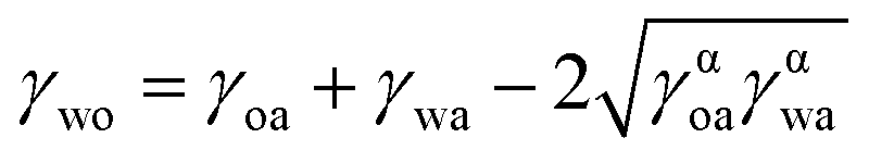
The contact angles and surface tensions of water and plant oil on the underlayer fabricated with DTMS modification of the nanoparticles were measured (see Table 1) to determine whether the underlayer fulfilled the following criteria for a stable SLIPS with plant oil:16
ΔE1 = R(γoa![[thin space (1/6-em)]](https://www.rsc.org/images/entities/char_2009.gif) cosθo − γwacosθw) − γwo > 0 cosθo − γwacosθw) − γwo > 0
| (1) |
|
ΔE2 = R(γoacosθo − γwacosθw) + γwa − γoa > 0
| (2) |
 | (3) |
| SiO2 concentration (wt%) | Dip speed (mm s−1) | WCA (°) (θA) | OCA (°) (θB) | ΔE1 | ΔE2 |
|---|---|---|---|---|---|
| 4 | 1.0 | 151.5 | 38 | 38.29 | 129.76 |
| 4 | 3.3 | 157.5 | 17 | 47.27 | 138.74 |
| 4 | 10.0 | 126.0 | 6 | 24.06 | 115.53 |
| 7 | 1.0 | 155.0 | 33 | 42.01 | 133.48 |
| 7 | 3.3 | 160.0 | 9 | 49.48 | 140.95 |
| 7 | 10.0 | 124.5 | 8 | 11.3 | 102.77 |
| 13 | 1.0 | 154.5 | 32 | 42.05 | 133.52 |
| 13 | 3.3 | 154.5 | 10 | 46.68 | 138.15 |
| 13 | 10.0 | 133.5 | 15 | 30.43 | 121.90 |
We varied the surface morphology to obtain surfaces with different enhanced wettabilities, which also affected the stability. Table 1 gives the wettabilities and stabilities of the different SLIPS samples. It was observed that, the higher the ΔE1 and ΔE2 values of the underlayer, the higher the stability. The present study revealed that a silica nanoparticle solution concentration of 7 wt% and dip speed of 3.3 mm s−1 produced the highest values of ΔE1 and ΔE2.
Assessment of durability
The stability of the plant oil SLIPS was evaluated for practical use in the medical field. Fig. 5A shows the trends of the sliding angle and transmittance of a sample of the SLIPS tilted at an angle of 30° over a week at room temperature. As can be observed, the SLIPS maintained a small sliding angle (<5°) and high transmittance (>85%). Furthermore, Fig. 5B shows that a water droplet on the surface of the plant oil SLIPS slid off with a small sliding angle (<5°) even after the subjection of the slip to a strong shearing force through spinning at 3000 rpm. This indicates that a sufficient amount of plant oil was retained on the surface. These results show that the capillary force of the oil–solid interface was enhanced by the surface roughness and outweighed the shearing force under rotation.35 | ||
| Fig. 5 Results of durability test. (A) shows the sliding angle and transmittance with respect to time determined by a long-term stability test. (B) shows the sliding angle after shearing testing. (C) shows the sliding angle with respect to the water showering time. (D) shows the kinetic coefficient of friction with respect to the number of abrasion cycles. | ||
We further evaluated the robustness against a constant high water pressure flux of 1.5 L min−1. Fig. 5C shows the water sliding angle on the plant oil SLIPS under the continuous shower. As can be observed, the sliding angle was maintained below 10° for 30 min. However, the sliding property gradually deteriorated thereafter until it was lost after 180 min. Nevertheless, the recast of plant oil on the deteriorated surface restored the sliding angle to the value of <5° before the shower. This indicates that the underlayer possessed a strong oil trapping ability. Fig. 3 shows the SEM image of the underlayer. A rough structure and many pores were observed. The lubricating oil spread over the structure and was captured by capillary force. Furthermore, the hydrophobicity of the underlayer prevented the infusion of water and protected the rough structure, thereby affording durability against water and recoverability of the slippery property.
Fig. 5D shows the robustness against mechanical pressure. Although the highly structured rough surface was inherently weak against mechanical pressure, the plant oil layer constituted a cushion between the wearing solid and the underlayer, thereby enhancing the mechanical durability.36 Fig. 5D shows the surface homogeneity with respect to the mechanical abrasion. As can be seen, the surface friction coefficient was maintained stable after 100 abrasion cycles, indicating that the surface was completely covered with the plant oil and the underlayer preserved its structure. However, the contact of the wearing solid with the exposed underlayer would alter the friction coefficient. This result supports the regeneration of the surface by recasting of the plant oil after deterioration (Fig. 5C).
Optical analysis
Fig. 6A shows the transmittances of the bare glass substrate, the underlayer with the nanoparticles but without plant oil, and the complete SLIPS with plant oil. As can be observed, the glass substrate exhibited a high transmittance, while the underlayer did not owing to the scattering by the nanoparticles. However, the infusion of plant oil increased the transmittance. We also examined the enhanced optical transparency in the visible range after infusing the plant oil into the underlayer (Fig. 6B). The increased transparency was measured by a HAZE meter, particularly to determine the scattering, which was found to be lower than the regular requirement for optical applications (haze < 5%) (Fig. 6C). The surfaces were observed to be hazy before the infusion of the oil, but the transparency became comparable to that of bare glass after the infusion. The porous structures of the silica-coated underlayer were bigger than the visible light wavelength; the surface therefore scattered the light, resulting in the hazy appearance. When plant oil (refractive index = 1.47) was impregnated into the underlayer with the silica coat (refractive index = 1.50), the resultant flat surface and matching refractive indexes reduced the surface light scattering and reflectance at the interface between the silica coat and the oil (Fig. 6D and S2†). The reflectance at the interface between the differing indexes is given by
 | (4) |
 | ||
| Fig. 6 (A) shows the transmittances of the underlayer without the plant oil layer (blue line), the complete SLIPS (red line), and the uncoated glass substrate (black line). (B) shows the transformation produced by infusion of the plant oil. The top figure was obtained by only the underlayer, and the bottom figure by the complete SLIPS. The black bar represents 1 cm. (C) shows the total transmittance (T.T.), parallel transmittance (P.T.), haze (HAZE), and diffusion (DIF.). (D) illustrates the decrease in scattering after infusion of the plant oil. | ||
Antifouling ability, anticoagulation, and endoscope application
To investigate the application of the fabricated SLIPS to a laparoscope, we performed an in vivo experiment. Body fluids including blood and interstitial fluid mainly consist of water (>90%) and the wettability is strongly affected by pH values. We therefore measured the sliding angle for pH-adjusted water valued between 1.82 and 11.02, as shown in Fig. 7A. The immiscibility of plant oil with water-based solutions limited the sliding angle to within 5°, indicating the potential of the SLIPS to repel almost all types of body fluids, including gastric. | ||
| Fig. 7 (A) shows the sliding angles for various liquids with different pH values. (B) illustrates the antifouling property. On the left, blood rolls over the substrate tilted a 30°. On the right are shown the samples after immersion in blood. In each picture, the uncoated glass substrate is on the left side, and the coated underlayer on the right. (C) and (D) illustrate the animal experiment, and show the inside of the mouse body and mouse stomach observed through the endoscope with and without the SLIPS. Dotted circles indicate vessels and tissues. (E) shows blood coagulation on the uncoated glass substrate and the SLIPS coated with the plant oil layer. The black bar indicates 10 μm. | ||
The plant oil SLIPS exhibited excellent liquid repellency as reflected by the low sliding angles for water and blood (<5°). The observed sliding angles compare favorably with those of SLIPS with fluorinated lubricants.41 Fig. 7B also shows that a 10 mL droplet of blood slid off the surface of the plant oil SLIPS without staining it. However, blood spread over and contaminated the bare glass substrate. Furthermore, the bare glass substrate and the complete plant oil SLIPS were soaked in pig blood (Fig. 7B). The latter exhibited good blood repellency, while blood adhered to and contaminated the surface of the former, resulting in a loss of transparency. These results confirm the ability of the oil SLIPS to repel both partially adhering blood (e.g., during the hemorrhage of a capillary) and fully covering blood (e.g., during a hemorrhage when using an endoscope).
Moreover, the plant oil SLIPS is highly flexible with regard to the employed substrate and can be fabricated using a flexible polyvinylidene chloride thin film for easy attachment and detachment from an endoscope lens. Fig. 7C shows the abdominal cavity of a mouse observed through an endoscope with its lens covered with the fabricated SLIPS film. A schematic illustration of the animal experiment is shown in Fig. S5.† The visibility through the endoscope with the SLIPS film was compared with that through an endoscope without the film. The latter was observed to be blurred, especially around blood vessels (see Fig. 7C), while the former was very clear. The SLIPS film did not obstruct the visibility when attached to the endoscope lens, but prevented the adhesion of blood and other body fluids to the lens.
We also used the endoscope to observe the inside of the mouse's stomach. Fig. 7D shows the views with and without the lens covered with the SLIPS film. Gastric fluid adhered to the uncovered endoscope lens, resulting in a blurred view, while the use of the SLIPS covering prevented the adhesion and ensured a clear view, as shown in Fig. 7C. This confirmed the antifouling performance of the plant oil SLIPS film in an acid environment like that of the stomach, and its potential application in the biomedical field.
Fig. 7E shows images of blood coagulation with respect to time. At the beginning of coagulation, the blood changed from liquid to solid, with the coagulated state having an irregular surface. On the bare glass, the blood began to coagulate rapidly after 18 min, while the coagulation on the plant oil SLIPS began after 20 min and was very slow. Blood coagulation behavior on SLIPS is different from that on bare glass. After coagulation, the blood clots on the SLIPS could be easily peeled off. This was due to the smaller contact area compared to the case of the bare glass. Moreover, the repelled blood on the SLIPS did not spread but assumed a rounded shape, thus preventing absorption.42,43 This chemical anticoagulation potential exhibited by the SLIPS was due to the presence of oleic acid in the plant oil.28,44 The oleic acid bound the blood lysine, which is responsible for coagulation, as well as antithrombin III, which functions as an anticoagulant. The overall coagulation reaction was thus controlled.44 For endoscope lens, our coating prevents blood clotting for 20 minutes that is enough for practical use because blood slides on coating immediately.
Conclusions
We developed an easy-to-fabricate SLIPS with enhanced biocompatible antifouling ability. The SLIPS utilizes plant oil as the lubricant, which is retained by the fine surface asperity of the underlayer. The SLIPS exhibited good repellency for blood and various liquids with differing pH values. The sliding angles of the different liquids on the SLIPS were within 5°. The trapping of the plant oil by the nanoscale asperity of the underlayer afforded good endurance against a water shower. The flat surface of the lubricated SLIPS also enhanced the transparency, which was comparable to that of bare glass. The observed properties of the plant oil SLIPS make it promising for application in medical devices. An experiment in which a film type of the SLIPS was used to cover the lens of an endoscope for inspecting the inside of a mouse confirmed its effectiveness for preventing the adherence of blood and other body tissues, thereby maintaining clear visibility through the scope.Acknowledgements
This work was supported by JSPS KAKENHI (grant number 26420710). We are deeply grateful to Dr Yoshio Hotta, Dr Kouji Fujimoto and Dr Kyu-Hong Kyung who supported this work and gave enormous helpful comments.Notes and references
- A. R. Roumm, L. Pizzi, N. I. Goldfarb and H. Cohn, Surg. Innov., 2005, 12, 261–287 CrossRef PubMed.
- G. Dedemadi, G. Sgourakis, C. Karaliotas, T. Christofides, G. Kouraklis and C. Karaliotas, Surg. Endosc., 2006, 20, 1099–1104 CrossRef CAS PubMed.
- E. P. Westebring-van der Putten, R. H. M. Goossens, J. J. Jakimowicz and J. Dankelman, Minim. Invasive. Ther. Allied. Technol., 2008, 17, 3–16 CrossRef CAS PubMed.
- A. Shah, Indian J. Pediatr., 2008, 75, 925–929 CrossRef PubMed.
- M. Mack, JAMA, 2001, 285, 568–572 CrossRef CAS PubMed.
- J. F. Buell, M. T. Thomas, S. Rudich, M. Marvin, R. Nagubandi, K. V. Ravindra, G. Brock and K. M. McMasters, Ann. Surg., 2008, 248, 475–486 Search PubMed.
- C. L. Garey, C. a. Laituri, D. J. Ostlie and S. D. St Peter, Pediatr. Surg. Int., 2010, 26, 451–456 CrossRef PubMed.
- T. B. Baker, C. L. Jay, D. P. Ladner, L. B. Preczewski, L. Clark, J. Holl and M. M. Abecassis, Surgery, 2009, 146, 817–825 CrossRef PubMed.
- E. P. Dimagno, J. L. Buxton, P. T. Regan, R. R. Hattery, D. A. Wilson, J. R. Suarez and P. S. Green, The Lancet, 1980, 629–631 CrossRef CAS.
- S. K. Harrel, T. G. Wilson and F. Rivera-Hidalgo, J. Clin. Periodontol, 2013, 40, 868–874 CrossRef PubMed.
- K. Sasaki, M. Tenjimbayashi, K. Manabe and S. Shiratori, ACS Appl. Mater. Interfaces, 2016, 8, 651–659 CAS.
- T. Sun, H. Tan, D. Han, Q. Fu and L. Jiang, Small, 2005, 1, 959–963 CrossRef CAS PubMed.
- D. Quéré, Annu. Rev. Mater. Res., 2008, 38, 71–99 CrossRef.
- L. Bocquet and E. Lauga, Nat. Mater., 2011, 10, 334–337 CrossRef CAS PubMed.
- A. Lafuma and D. Quéré, Nat. Mater., 2003, 2, 457–460 CrossRef CAS PubMed.
- T.-S. Wong, S. H. Kang, S. K. Y. Tang, E. J. Smythe, B. D. Hatton, A. Grinthal and J. Aizenberg, Nature, 2011, 477, 443–447 CrossRef CAS PubMed.
- L. Zhu, J. Xue, Y. Wang, Q. Chen, J. Ding and Q. Wang, ACS Appl. Mater. Interfaces, 2013, 5, 4053–4062 CAS.
- S. B. Subramanyam, K. Rykaczewski and K. Varanasi, Langmuir, 2013, 29, 13414–13418 CrossRef CAS PubMed.
- S. Yang, R. Qiu, H. Song, P. Wang, Z. Shi and Y. Wang, Appl. Surf. Sci., 2015, 328, 491–500 CrossRef CAS.
- L. Xiao, J. Li, S. Mieszkin, A. Di Fino, A. S. Clare, M. E. Callow, J. a. Callow, M. Grunze, A. Rosenhahn and P. a. Levkin, ACS Appl. Mater. Interfaces, 2013, 5, 10074–10080 CAS.
- C. Howell, T. L. Vu, J. J. Lin, S. Kolle, N. Juthani, E. Watson, J. C. Weaver, J. Alvarenga and J. Aizenberg, ACS Appl. Mater. Interfaces, 2014, 6, 13299–13307 CAS.
- A. K. Epstein, T.-S. Wong, R. A. Belisle, E. M. Boggs and J. Aizenberg, Proc. Natl. Acad. Sci. U. S. A., 2012, 109, 13182–13187 CrossRef CAS PubMed.
- D. C. Leslie, A. Waterhouse, J. B. Berthet, T. M. Valentin, A. L. Watters, A. Jain, P. Kim, B. D. Hatton, A. Nedder, K. Donovan, E. H. Super, C. Howell, C. P. Johnson, T. L. Vu, D. E. Bolgen, S. Rifai, A. R. Hansen, M. Aizenberg, M. Super, J. Aizenberg and D. E. Ingber, Nat. Biotechnol., 2014, 32, 1134–1140 CrossRef CAS PubMed.
- N. MacCallum, C. Howell, P. Kim, D. Sun, R. Friedlander, J. Ranisau, O. Ahanotu, J. J. Lin, A. Vena, B. Hatton, T.-S. Wong and J. Aizenberg, ACS Biomater. Sci. Eng., 2015, 1, 43–51 CrossRef CAS.
- S. Anand, A. T. Paxson, R. Dhiman, J. D. Smith and K. K. Varanasi, ACS Nano, 2012, 6, 10122–10129 CrossRef CAS PubMed.
- K. S. Khalil, S. R. Mahmoudi, N. Abu-Dheir and K. K. Varanasi, Appl. Phys. Lett., 2014, 105, 18–22 Search PubMed.
- V. Multanen, G. Chaniel, R. Grynyov, R. Y. Loew, N. Kyle Siany and E. Bormashenko, Colloids Surf., A, 2014, 461, 225–230 CrossRef CAS.
- K. Manabe, K.-H. Kyung and S. Shiratori, ACS Appl. Mater. Interfaces, 2015, 7, 4763–4771 CAS.
- D. F. Miranda, C. Urata, B. Masheder, G. J. Dunderdale, M. Yagihashi and A. Hozumi, APL Mater., 2014, 2, 056108/1–056108/6 CAS.
- D. Fluoride, N. A. Systematic, A. L. Choi, G. Sun, Y. Zhang and P. Grandjean, Environ. Health Perspect., 2012, 120, 1362–1369 CrossRef PubMed.
- L. Ahrens, J. Environ. Monit., 2011, 13, 20–31 RSC.
- J. T. Simpson, S. R. Hunter and T. Aytug, Rep. Prog. Phys., 2015, 78, 086501 CrossRef PubMed.
- T. Krupenkin, J. A. Taylor, P. Kolodner and M. Hodes, Bell Syst. Tech. J., 2005, 10, 161–170 CrossRef.
- P. Zhang, H. Chen, L. Zhang, T. Ran and D. Zhang, Appl. Surf. Sci., 2015, 355, 1083–1090 CrossRef CAS.
- P. Kim, M. J. Kreder, J. Alvarenga and J. Aizenberg, Nano Lett., 2013, 13, 1793–1799 CrossRef CAS PubMed.
- M. Tenjimbayashi and S. Shiratori, J. Appl. Phys., 2014, 116, 114310 CrossRef.
- W. Wu, X. Wang, X. Liu and F. Zhou, ACS Appl. Mater. Interfaces, 2009, 1, 1656–1661 CAS.
- J. Yong, Q. Yang, F. Chen, H. Bian, G. Du, U. Farooq and X. Hou, Adv. Mater. Interfaces, 2015, 2, 1400388 Search PubMed.
- F. Li, M. Du, Z. Zheng, Y. Song and Q. Zheng, Adv. Mater. Interfaces, 2015, 1–7 Search PubMed.
- A. a. Darhuber, S. M. Troian, J. M. Davis, S. M. Miller and S. Wagner, J. Appl. Phys., 2000, 88, 5119–5126 CrossRef CAS.
- I. Okada and S. Shiratori, ACS Appl. Mater. Interfaces, 2014, 6, 1502–1508 CAS.
- J. D. Smith, R. Dhiman, S. Anand, E. Reza-Garduno, R. E. Cohen, G. H. McKinley and K. K. Varanasi, Soft Matter, 2013, 9, 1772–1780 RSC.
- M. Nosonovsky, Nature, 2011, 477, 412–413 CrossRef CAS PubMed.
- J. Mandl, B. Tanács, Z. Spolarics, T. Garzó, I. Mucha, F. Antoni, R. Machovich and I. Horváth, Thromb. Res., 1984, 35, 407–414 CrossRef CAS PubMed.
Footnote |
| † Electronic supplementary information (ESI) available: Contact angle water and plant oil, on surfaces fabricated by different SiO2 concentration and dip speed, SEM image of underlayer and oil-infused surface, image through coated endoscope, cost for preparation. See DOI: 10.1039/c6ra08390k |
| This journal is © The Royal Society of Chemistry 2016 |