Bioactive borophosphosilicate-polycaprolactone hybrid biomaterials via a non-aqueous sol gel process†
Dibakar Mondala,
Amin S. Rizkalla*abc and
Kibret Mequanint*ab
aDepartment of Chemical and Biochemical Engineering, The University of Western Ontario, London, ON, Canada N6A 5B9. E-mail: kmequani@uwo.ca; arizkall@uwo.ca; Fax: +1 519 661 3498; Tel: +1 519 661 2111 ext. 88573 Tel: +1 519 661 2111 ext. 86086
bBiomedical Engineering Graduate Program, The University of Western Ontario, London, ON, Canada N6A 5B9
cSchulich School of Medicine and Dentistry, The University of Western Ontario, London, ON, Canada N6A 5B9
First published on 21st September 2016
Abstract
In this study, a non-aqueous sol–gel process was utilized to prepare novel class II hybrid biomaterials based on functionalized polycaprolactone (PCL) diol and borophosphosilicate glass (BPSG) as potential scaffold material for bone tissue engineering applications. PCL diol was first functionalized by reacting with (3-glycidoxypropyl)trimethoxysilane. The functionalized PCL (PCL–Si) was condensed with trimethyl borate, tetraethyl orthosilicate and triethyl phosphate via non-aqueous sol–gel reactions to form covalently bonded organic–inorganic networks. FTIR, TGA, XRD, and solid state 29Si CP-MAS NMR analyses revealed that the hybrid materials were successfully prepared. Furthermore, the hybrids were amorphous and transparent up to 60 wt% of PCL–Si content. Specifically, the organic–inorganic networks had a dominant T3 network since Si–C bond from PCL–Si is covalently bonded with the inorganic glass network and resulted in a class II hybrid. EDX and XPS studies showed uniform distribution of the various elements making up the hybrid materials. When incubated with simulated body fluids (SBF), the present hybrid materials were able to stimulate the deposition of crystalline hydroxyapatite. This study demonstrated, for the first time, the chemical reactivity of calcium-free BPSG and PCL–BPSG hybrids and their ability to deposit hydroxyapatite when incubated in SBF. The present study is also the first to incorporate B2O3 as a glass component in class II organic–inorganic hybrid biomaterials.
1. Introduction
Biomaterials used for bone tissue engineering scaffolds should be osteoconductive and osteoinductive while exhibiting appropriate porosity and pore sizes to allow for cell infiltration, tissue growth and metabolic waste removal. The rate of degradation must also match the rate of tissue formation so that the newly formed bone can replace the biomaterial.1–3 One of the challenges associated with developing biomaterials for bone tissue engineering is that no single material meets the above-mentioned properties.4 Bioactive conventional composite materials consisting of organic and inorganic components have been proposed to be a solution to this problem.5,6 However, these composites have micro-scale domain sizes leading to distinct phases within these materials. This, in turn, results in non-uniform physical, chemical, mechanical and biological properties at the nano or molecular level making them unsuitable as bone biomaterials.4Since bone is a combination of both organic and inorganic components with molecular level interactions between them, a logical strategy in bone tissue engineering is to design hybrid biomaterials. Hybrid biomaterials made by combining organic and inorganic components may be class I hybrids (if the interactions between the components are weak hydrogen bonding and/or van der Waal's forces) or class II hybrids (if the interactions between the organic and inorganic components occur by covalent bonding).7,8 As hybrid biomaterials exhibit single phases on molecular or macromolecular level, careful choice of both the organic and/or inorganic moieties and the synthesis approach affords to design novel materials with tailored properties for a biological environment.
The sol–gel process is a unique way to synthesize organic–inorganic hybrid materials at mild temperatures to avoid the degradation of the organic component.9 In the last fifteen years, sol–gel derived organic–inorganic hybrid materials based on silicon alkoxide and incorporating chitosan,10 gelatin,11 poly(vinyl alcohol),12,13 and poly glutamic acid14 have been reported. These hybrids were synthesized through aqueous sol–gel process in which the silicon alkoxide hydrolysis and condensation reactions were carried out using water as a reactant and medium. The necessity to use water severely constrains the choice of the organic polymers to be hydrophilic and water soluble thus precluding many desirable biodegradable polymers that are not water soluble. The use of water miscible organic solvents as co-solvents alleviates this difficulty15,16 but the process is neither versatile nor straightforward.
The above limitations may be addressed by the use of non-aqueous sol–gel approach17–19 which could afford a one-pot synthesis of bioactive organic–inorganic hybrid materials with different biodegradable polymers. In the current work we propose the utility of non-aqueous sol–gel method to prepare novel bioactive class II borophosphosilicate hybrid bone biomaterials incorporating methoxysilane functionalized polycaprolactone (PCL–Si). Bioactive glasses containing boron exhibit higher bioactivity than conventional SiO2–P2O5–CaO glass.20–25 Boron in bioactive glass matrix also inhibits the formation of silica-rich layer which results in relatively faster rate of degradation and induction of cell invasion and apatite deposition on its surface.20–22,26,27 Despite these benefits, organic–inorganic hybrid biomaterials containing boron have not been reported. In view of this, the objective of the present study is to synthesize and characterize a class II hybrid biomaterial consisting of PCL and SiO2–P2O5–B2O3 glass in a non-aqueous sol gel route. To the best of our knowledge, this study is the first to report the synthesis of PCL-borophosphosilicate (PCL–SiO2–P2O5–B2O3) organic–inorganic class II hybrid biomaterial.
2. Materials and methods
2.1 Materials
Poly (ε-caprolactone) diol (PCL diol; MW 3000 g mol−1) was obtained from Tri-Iso Inc. (Cardiff, CA). (3-Glycidoxypropyl) trimethoxysilane (GPTMS, 97%) and trimethyl borate (TMB, 99%) were purchased from Alfa Aesar (Ward Hill, MA). Tetraethyl orthosilicate (TEOS, 98%) and triethyl phosphate (TEP, 99.8%) were purchased from Sigma-Aldrich (Milwaukee, WI). Acetic acid glacial (AcOH) and toluene were purchased from Caledon Laboratory Chemicals (Georgetown, ON). Acetone, methanol and ethanol were purchased from BDH Chemicals (Toronto, ON). All chemicals for preparing simulated body fluid (SBF) were purchased from Sigma-Aldrich (Milwaukee, WI).2.2 Functionalization of poly (ε-caprolactone) diol
Trimethoxysilane functionalized PCL (hereinafter referred as PCL–Si) was synthesised by the reaction of PCL diol with GPTMS in the presence of trimethyl borate (TMB) as a Lewis acid catalyst and toluene as the solvent. The molar ratio of PCL diol, GPTMS and TMB was 1![[thin space (1/6-em)]](https://www.rsc.org/images/entities/char_2009.gif) :
:![[thin space (1/6-em)]](https://www.rsc.org/images/entities/char_2009.gif) 4
4![[thin space (1/6-em)]](https://www.rsc.org/images/entities/char_2009.gif) :
:![[thin space (1/6-em)]](https://www.rsc.org/images/entities/char_2009.gif) 0.00025. The reaction was carried on a three-necked round bottom flask connected with a condenser, a thermometer and a gas inlet/outlet under dry N2 gas flow at 70 °C. After 24 h reaction, the product was purified by repeated precipitation in cold methanol. The product was then dried under vacuum at room temperature for 24 h.
0.00025. The reaction was carried on a three-necked round bottom flask connected with a condenser, a thermometer and a gas inlet/outlet under dry N2 gas flow at 70 °C. After 24 h reaction, the product was purified by repeated precipitation in cold methanol. The product was then dried under vacuum at room temperature for 24 h.
2.3 Synthesis of PCL-borophosphosilicate hybrid biomaterials
The borophosphosilicate glass (BPSG) composition synthesized in this study was 91 mol% SiO2, 5 mol% B2O3 and 4 mol% P2O5. Pre-determined amount of TEOS was added to a solution of 15 vol% acetic acid in acetone. After 6 h of mixing TEP was added to the sol and stirred for 15 min. PCL–Si was separately dissolved in acetone (10% w/v) and added to the sol followed by addition of TMB. Molar ratio of (TEOS + TEP + TMB) to acetic acid was maintained at 1![[thin space (1/6-em)]](https://www.rsc.org/images/entities/char_2009.gif) :
:![[thin space (1/6-em)]](https://www.rsc.org/images/entities/char_2009.gif) 4. The contents were stirred gently for 12 h at ambient temperature, then transferred into a Teflon mold and kept in a fume hood for 3 days covered by aluminum foil with pinholes. After 3 days, ethanol (10 vol% of initial acetone) was added to the sol to reduce potential cracks that may develop in the hybrid gel during solvent evaporation and drying. Pure control glass (SiO2–P2O5–B2O3) was prepared using similar procedures as in the case of the PCL–BPSG hybrids. Following gelation of the sols, the gel was first dried for 2 days in a fume hood followed by vacuum drying (225 mm Hg) for one day at 50 °C. The resultant transparent class II PCL-BPSB hybrid materials were transferred into sealed glass vials filled with de-ionized (DI) water and shaken for 1 day at 120 rpm to wash the unreacted AcOH and solvents. The chemical composition of the synthesized PCL-BPSG hybrid biomaterials ranged between 10–70 wt% PCL–Si and 90–30 wt% BPSG. An example clarifying the nomenclature used in this study to identify a chemical composition of a hybrid biomaterial is presented as follows: 30H represents 30 wt% PCL–Si and 70 wt% BPSG.
4. The contents were stirred gently for 12 h at ambient temperature, then transferred into a Teflon mold and kept in a fume hood for 3 days covered by aluminum foil with pinholes. After 3 days, ethanol (10 vol% of initial acetone) was added to the sol to reduce potential cracks that may develop in the hybrid gel during solvent evaporation and drying. Pure control glass (SiO2–P2O5–B2O3) was prepared using similar procedures as in the case of the PCL–BPSG hybrids. Following gelation of the sols, the gel was first dried for 2 days in a fume hood followed by vacuum drying (225 mm Hg) for one day at 50 °C. The resultant transparent class II PCL-BPSB hybrid materials were transferred into sealed glass vials filled with de-ionized (DI) water and shaken for 1 day at 120 rpm to wash the unreacted AcOH and solvents. The chemical composition of the synthesized PCL-BPSG hybrid biomaterials ranged between 10–70 wt% PCL–Si and 90–30 wt% BPSG. An example clarifying the nomenclature used in this study to identify a chemical composition of a hybrid biomaterial is presented as follows: 30H represents 30 wt% PCL–Si and 70 wt% BPSG.
2.4 Fabrication of porous scaffold
3D porous scaffolds of PCL–BPSG hybrid were fabricated by a compression moulding and salt leaching technique. 50H hybrid biomaterial was ground in a planetary ball mill to get fine powder. NaCl crystals were sieved to yield 150–250 μm size range. Mixtures of NaCl ranging from 40 to 70 vol% and hybrid particles were prepared by mechanical mixing. The mixtures were compression moulded for 1 h (1 MPa and 50 °C) in a stainless steel mould to produce 3 mm in height and 6 mm in diameter scaffolds. NaCl particles were leached out with excess deionised water by shaking at 100 rpm for 2 days. Fresh water was replaced every 2 h for the first 10 h, then 2–3 times a day. The scaffolds were dried in vacuum at room temperature.2.5 In vitro bioactivity tests
The in vitro bioactivity tests were carried out by studying the deposition of hydroxyapatite (HA) on the surface of BPSG and PCL–BPSG hybrid disk samples (6 mm in diameter and 2 mm in thickness) following incubation in simulated body fluid (SBF). The SBF solution has a composition and concentration similar to those of the inorganic part of human blood plasma and was prepared as described in the literature.28 The as-prepared hybrid monoliths were pulverized by a planetary ball mill (Laval Lab Inc., Germany) for 5 min; then 0.07 g of powder was weighed and heat pressed (Carver Inc., Wabash, IN) at 60 °C and 35 MPa for 15 min using a custom-made stainless steel mold to prepare cylindrical disks. Each specimen was incubated in 9 mL of SBF contained in polypropylene bottles covered with a tight lid. The bottles were placed in an orbital shaker (MaxQ4000, Barnstead Lab-line, IL) at 120 rpm and 37 °C at different time interval ranging from 3 to 10 days. Two parallel experiments were performed; in the first one the SBF solution was refreshed daily while in second one SBF was not refreshed during the incubation times. After each incubation period, the disks were rinsed with DI water and dried under vacuum at room temperature for 24 h.2.6 Fourier transform infrared spectroscopy (FTIR)
Functionalized polycaprolactone (PCL–Si) was ground in a mortar and pestle under liquid nitrogen. Pure BPSG and PCL–BPSG hybrid monoliths were ground in a planetary ball mill to get fine powder. FTIR spectra were obtained using a Nicolet 6700 FT-IR Spectrometer (Thermo Scientific, USA) at a resolution of 4 cm−1 with a sample scan of 32 to identify specific functional groups. All spectra were analyzed using OMNIC series software.2.7 1H and 29Si nuclear magnetic resonance spectroscopy (NMR)
One dimensional 1H-NMR spectra were recorded at room temperature using a Varian INOVA 600 spectrometer (Agilent Technologies, USA) operating at 100.61 MHz using d-chloroform as the solvent. Solid-state cross-polarization magic-angle spinning (CPMAS) 29Si NMR spectra were acquired using a Varian Infinity Plus 400 NMR spectrometer (ν(1H) = 399.5 MHz, ν(29Si) = 79.4 MHz) equipped with a Varian HXY triple-resonance 7.5 mm magic-angle spinning NMR probe. The samples were packed tightly into 7.5 mm outer diameter ZrO2 rotors and rotated at 5.5 kHz. A total of 4000 scans were summed using a 6.75 μs 1H 90-degree pulse, 2 ms contact time, 10.24 ms acquisition time, 7 s recycle delay, 50 kHz spectral width and continuous-wave 1H decoupling during acquisition. For processing, two zero-fills and 30 Hz line broadening were applied to the FID before Fourier transformation. The NMR spectra were referenced with respect to tetramethylsilane (δ(29Si) = 0.0 ppm) by setting the high-frequency peak of tetrakis(trimethylsilyl)silane to −9.8 ppm.2.8 Thermogravimetric analysis (TGA)
TGA experiments were performed using a TGA analyser SDT Q600 (TA Instruments Inc., New Castle, DE) from 25–800 °C under air atmosphere at 10 °C min−1 heating rate. 10–15 μg samples were used per experiment. The residual masses at 800 °C were recorded to calculate the actual organic–inorganic ratio in the hybrid materials.2.9 X-ray diffraction (XRD)
XRD was performed using an X-ray diffractometer AXS D2 PHASER (Bruker Corporation, USA) operating on CuKα radiation with λ = 1.5418 Å. The measurements were conducted in 30 kV and 10 mA in 2θ range 10–60° with steps of 0.049°. PCL–BPSG hybrids and controls (PCL–Si and BPSG) were incubated in SBF and dried under vacuum at ambient temperature for 24 h. XRD experiments were carried on the surfaces exposed to SBF. XRD measurements were done on all samples before incubation; but only selected samples were used after incubation in SBF.2.10 Scanning electron microscopy (SEM) and energy dispersive X-ray spectroscopy (EDX)
Surface morphology of BPSG and PCL–BPSG hybrid materials were visualized by using LEO 1540XB SEM (Hitachi, Japan). Elemental distribution and chemical composition of the hybrid sample were further analyzed by using an EDX detector attached to the LEO 1540XB SEM. The specimen surfaces were coated with Osmium in Osmium Plasma Coater (OPC80T, Filgen Inc. Japan) and 3 iterations per sample were used to gain the EDX spectra. Samples incubated in SBF were dried under vacuum at room temperature for 24 h before SEM imaging. Hydroxyapatite (HA) deposition on the surface of glass and hybrid materials were visualized by using LEO 1530 (Zeiss, Oberkochen, Germany) at 5 mm working distance and 3 kV of electron beam voltage. Prior to SEM imaging, the specimen surfaces were coated with 5 nm Osmium.2.11 X-ray photoelectron spectroscopy (XPS)
The XPS analyses were carried out on pulverized samples using a Kratos Axis Ultra spectrometer using a monochromatic Al Kα source (15 mA, 14 kV). The instrument work function was calibrated to give a binding energy (BE) of 83.96 eV for the Au 4f7/2 line for metallic gold and the spectrometer dispersion was adjusted to give a BE of 932.62 eV for the Cu 2p3/2 line of metallic copper. The Kratos charge neutralizer system was used on all specimens. Survey scan analyses were carried out with an analysis area of 300 × 700 microns and a pass energy of 160 eV. High resolution analyses were carried out with an analysis area of 300 × 700 microns and a pass energy of 20 eV. Spectra have been charge corrected to the main line of the carbon 1 s spectrum (adventitious carbon) set to 284.8 eV. Spectra were analysed using CasaXPS software (version 2.3.14).3. Results and discussion
3.1 Preparation of functionalized PCL–Si
In this study, PCL was first functionalized with trimethoxysilane by reacting with GPTMS. The epoxy ring from GPTMS opened in the presence of a Lewis acid catalyst and react with hydroxyl groups of PCL diol,29 leaving the PCL functionalized with methoxysilane groups. In non-aqueous sol gel process, these methoxysilanes underwent carboxylation and polycondensation with![[triple bond, length as m-dash]](https://www.rsc.org/images/entities/char_e002.gif) Si–OH,
Si–OH, ![[double bond, length as m-dash]](https://www.rsc.org/images/entities/char_e001.gif) B–OH and
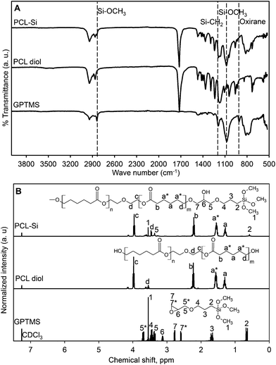
B–OH and ![[double bond, length as m-dash]](https://www.rsc.org/images/entities/char_e001.gif) (PO)–OH. Both FTIR and 1H-NMR results showed PCL diol was successfully functionalized at both ends by reacting it with GPTMS. The FTIR spectra (Fig. 1A) showed peaks at 1080 and 2840 cm−1 for both GPTMS and PCL–Si corresponding to the stretching vibrations of Si–O bond in methoxysilane (Si–OCH3). The oxirane C–O stretching at 915 cm−1 was absent while Si–C bond at 1120 cm−1 appeared from the PCL–Si spectrum which is expected. Comparing the 1H-NMR spectra (Fig. 1B) for GPTMS, PCL diol and PCL–Si, disappearances of the signals in PCL–Si spectrum for oxirane ring adjacent protons at δ = 3.13, 2.6 and 2.78 ppm denoted as 6, 7* and 7 respectively in GPTMS spectrum provided a strong agreement with the FTIR data. Signals from proton denoted as 6 in GPTMS spectrum merged with methylene proton denoted as c in PCL–Si after functionalization. Also signals from proton 3 and 4 merged with a* and 4 respectively. Signals for protons from methoxy groups in methoxysilane of GPTMS remained the same after functionalization in PCL–Si spectrum indicating that PCL was functionalized with trimethoxysilane group from GPTMS.
(PO)–OH. Both FTIR and 1H-NMR results showed PCL diol was successfully functionalized at both ends by reacting it with GPTMS. The FTIR spectra (Fig. 1A) showed peaks at 1080 and 2840 cm−1 for both GPTMS and PCL–Si corresponding to the stretching vibrations of Si–O bond in methoxysilane (Si–OCH3). The oxirane C–O stretching at 915 cm−1 was absent while Si–C bond at 1120 cm−1 appeared from the PCL–Si spectrum which is expected. Comparing the 1H-NMR spectra (Fig. 1B) for GPTMS, PCL diol and PCL–Si, disappearances of the signals in PCL–Si spectrum for oxirane ring adjacent protons at δ = 3.13, 2.6 and 2.78 ppm denoted as 6, 7* and 7 respectively in GPTMS spectrum provided a strong agreement with the FTIR data. Signals from proton denoted as 6 in GPTMS spectrum merged with methylene proton denoted as c in PCL–Si after functionalization. Also signals from proton 3 and 4 merged with a* and 4 respectively. Signals for protons from methoxy groups in methoxysilane of GPTMS remained the same after functionalization in PCL–Si spectrum indicating that PCL was functionalized with trimethoxysilane group from GPTMS.
In addition to FTIR and NMR results, TGA data showed that the PCL–Si was successfully prepared. While the PCL diol completely degraded at 535 °C, the functionalized PCL–Si had residual mass (4.0 ± 0.07 wt%) left at 800 °C, attributed to the SiO2 from the silane group of GPTMS bonded with PCL diol and, was in agreement with that calculated from reaction stoichiometry (ESI, Fig. S1†).
3.2 Preparation of class II PCL–BPSG hybrid biomaterials
Non-aqueous sol–gel process involves alkoxylation and polycondensation reactions of organic precursors of metal or metalloid to form metal oxides or glass systems in the absence of water. For this work, it was advantageous over conventional aqueous sol–gel since we were able to incorporate water insoluble PCL into the hybrid matrix.18,30–32 Tetraethyl orthosilicate, triethyl phosphate and trimethyl borate reacted with AcOH such that the alkyl groups are replaced by the acetate on silicon, phosphorus and boron atoms, followed by the nonhydrolytic hydroxylation of acetate derivatives, as well as the esterification of AcOH, with in situ generation of water.33–35 The reaction between TEOS and AcOH is quite slow and required a longer reaction time (ca. double) compared to other reagents such as formic acid.35 In our system, however, formic acid was avoided since it resulted in phase-separation of trimethyl borate. This explains the prolonged gelation time taken during the synthesis of the PCL–BPSG hybrid biomaterials. As the PCL–Si content increased from 10% to 70%, the gelation time was decreased from 7 days to 5 days. Although trace amount of water is known to be generated during the non-aqueous sol–gel process,35 it did not cause phase separation of PCL from the inorganic matrix owing to the functionalization thus leading to co-condensation of the different inorganic components to form transparent and amorphous PCL–BPSG hybrid matrices.3.3 Solid state 29Si-MAS NMR, FTIR, and thermal analyses of class II PCL–BPSG hybrid biomaterials
To study organic–inorganic bridging, solid-state 29Si-MAS NMR was conducted for BPSG and 50H hybrid materials (Fig. 2A). In silica networks, if the silicon atom is bonded to four oxygen atoms, then the resultant structure is designated as Q network. However, if a silicon atom is bonded to three oxygen atoms and one carbon atom, then the structure is designated as T network.36 Using 29Si-NMR it is possible to detect the Q and T networks in BPSG and PCL–BPSG hybrids. Both of BPSG and 50H exhibited quaternary Si–O–Si bridging networks, which is denoted as Q4 network (superscript indicates the number of Si–O–Si framework connections with respect to the silicon atom). Chemical shifts at δ = −92, −100 and −109 ppm were associated with Q2, Q3 and Q4 structures respectively. The dominant network was Q3 due to the fact that the synthesized materials were not heated at high temperature and therefore resulted in Si–OH or Si–OR at one end. Chemical shifts at δ = −57 and −64 ppm denoted as T2 and T3 were attributed to the Si–O–Si bridging networks with Si–C at one end. The control BPSG did not have any peak for T networks because it has no Si–C bonding associated with Si–O–Si bridging network. In contrast, 50H spectrum showed a T3 network since Si–C bond from PCL–Si is covalently bonded with the inorganic glass network and resulted in a class II hybrid. In the FTIR spectra of PCL-BPSG hybrids (Fig. 2B), characteristic peaks at 1072 cm−1 attributed to Si–O–Si stretching and the peaks at 920 and 670 cm−1 attributed to Si–O–B stretching vibration are observed. The peak at 1310 cm−1 is associated with P![[double bond, length as m-dash]](https://www.rsc.org/images/entities/char_e001.gif) O bond from the glass networks. The peaks observed at 1730–1750 cm−1 of PCL–Si and hybrids are due to the non-bonded carbonyl groups. A shift of the carbonyl peak from 1730 to 1750 cm−1 was observed with the increase in the amount of PCL–Si (ESI Fig. S2†). If hydrogen bonding between C
O bond from the glass networks. The peaks observed at 1730–1750 cm−1 of PCL–Si and hybrids are due to the non-bonded carbonyl groups. A shift of the carbonyl peak from 1730 to 1750 cm−1 was observed with the increase in the amount of PCL–Si (ESI Fig. S2†). If hydrogen bonding between C![[double bond, length as m-dash]](https://www.rsc.org/images/entities/char_e001.gif) O group and
O group and ![[triple bond, length as m-dash]](https://www.rsc.org/images/entities/char_e002.gif) Si–OH was the mode of interaction (class I hybrids), the carbonyl peak shifting would have occurred at a wave number lower than 1730 cm−1, which is not the case. This is a clear indication that class II hybrids were indeed formed in the present study.
Si–OH was the mode of interaction (class I hybrids), the carbonyl peak shifting would have occurred at a wave number lower than 1730 cm−1, which is not the case. This is a clear indication that class II hybrids were indeed formed in the present study.
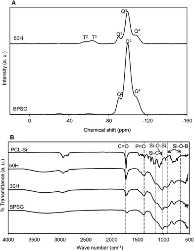 | ||
| Fig. 2 (A) Solid state 29Si-CPMAS NMR of pure glass (BPSG) and 50H hybrid material. (B) FTIR spectra of PCL–BPSG hybrid materials (30H and 50H) along with pure BPSG and PCL–Si. | ||
TGA was used to evaluate the thermal stability and to estimate both the organic and inorganic contents (calculated based upon the residual weight at 800 °C) of the PCL–BPSG hybrid biomaterials (Table 1).
| Hybrid sample | Mass loss, Wt% | Residual mass at 800 °C, Wt% | Inorganic/organic ratio |
|---|---|---|---|
| 10H | 11 | 65 | 85/15 |
| 20H | 17 | 60 | 78/22 |
| 30H | 23 | 54 | 70/30 |
| 40H | 28 | 49 | 63/37 |
| 50H | 31 | 45 | 59/41 |
The calculated organic–inorganic ratios of the different hybrid compositions from the TGA thermograms were in good agreement with the theoretical compositions. The PCL–Si underwent degradation where complete decomposition of the polymer occurred between 310 °C and 470 °C with an inflection temperature at 419 °C (ESI Fig. S2 and S3B†). In contrast, BPSG exhibited two distinct stages of degradation and showed approximately 19 wt% weight loss below 270 °C, which could have resulted from the loss of water, solvents, and incomplete condensation of the hydrolyzed precursor compounds (specifically TEOS). The weight loss of BPSG at temperatures (270–800 °C) was insignificant. The calculated residual weight at 800 °C was 71 wt% of the initial weight. The TGA thermograms of the PCL–BPSG hybrid materials displayed double stage thermal decomposition. In a similar fashion to BPSG, the first weight loss in case of the synthesized hybrids that took place below 270 °C was due to the loss of water, residual solvents and incomplete condensation of the hydrolyzed precursor compounds. The second stage weight loss (270–550 °C) was due to the decomposition of PCL. Interestingly, as the PCL content increased from 10H to 50H, the decomposition temperature range of the hybrid materials broadened. With increased PCL content, the residual weight at 800 °C decreased which was expected.
3.4 Phase identification and chemical composition of class II PCL–BPSG hybrid materials
Hybrid materials whose compositions ranged from 10H to 50H exhibited no diffraction peaks, indicating that the synthesized hybrid materials were completely amorphous similar to the control BPSG pure glass (Fig. 3A). On the other hand, PCL diol and PCL–Si exhibited semi-crystalline structures having two diffraction peaks at 2θ values, 21.5° and 22.1°, which were assigned to the (110) and (111) planes.37 Hybrid 60H, exhibited small diffraction peaks at 2θ values similar to those observed for PCL. This might have been attributed to either moderate phase separation or to the formation of PCL clusters within the hybrid matrix. Despite the fact that 10H to 50H were prepared from semi-crystalline PCL–Si, their amorphous nature strongly indicated the molecular scale interactions between BPSG and PCL phases. Furthermore digital photos of BPSG and PCL–Si (used as controls) and 30H and 50H displayed in Fig. 3B corroborated with XRD data providing evidence for molecular interactions between the organic and inorganic constituents of the hybrid materials. When the domain sizes of hybrid materials is reduced below the visible wavelength of light, the interaction between the different phases occur at the molecular level and reflection, diffraction or absorbance of photons will be reduced drastically resulting in a transparent material.8 However, depending on the composition of organic and inorganic precursors a class II hybrid material could lose its transparency as the homogenous distribution of the components on a molecular level is affected.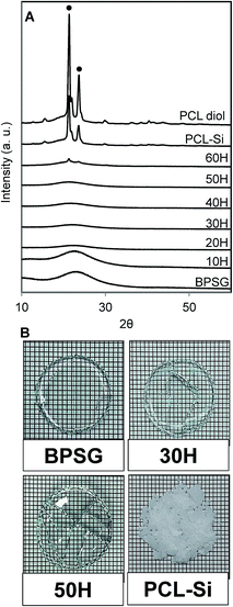 | ||
| Fig. 3 (A) XRD patterns of PCL–BPSG hybrid materials with pure BPSG, PCL–Si and PCL diol (● denotes PCL peak), (B) digital photos of as-prepared dried glass and hybrid materials. Additional digital photos of as-prepared dried hybrid materials 10H, 20H, 40H, 60H and 70H are shown in ESI Fig. S4.† | ||
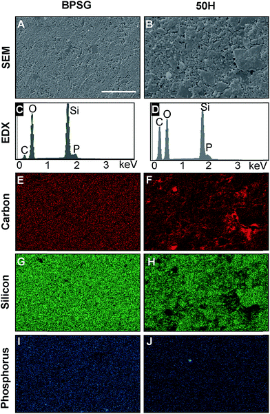
The surface morphology and elemental distributions for BPSG and 50H are presented in Fig. 4. 50H exhibited rougher surface topography and larger grain size compared to the BPSG surface. Elemental analyses revealed that 50H contained higher amount of carbon due to the presence of 50 wt% PCL.
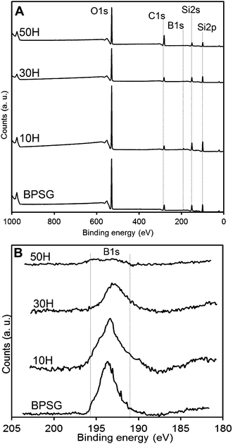
The presence of carbon in BPSG could be due to incomplete hydrolysis of precursor compounds or solvent entrapment. Elemental mapping for carbon, silicon and phosphorus revealed that they were all homogenously distributed in BPSG and PCL–BPSG hybrid surfaces. Phosphorus and silicon quantification revealed good agreement between the experimental and theoretical compositions (Table 2). Since EDX was unable to detect boron, we examined it using XPS. Fig. 5 showed XPS data for 50H (50% BPSG), 30H (70% BPSG), 10H (90% BPSG) and control BPSG (100% glass). In all the hybrid samples, boron was detected proportional to the amount of BPSG incorporated. The quantified elemental boron content was 1.1% for BPSG; 1% for 10H, 0.8% for 30H and 0.3% for 50H (ESI Table S1†) demonstrating the incorporating B2O3 as a glass component in a class II hybrid.
| Elements | Pure glass (BPSG) | 50H | ||
|---|---|---|---|---|
| Theoretical (wt%) | Experimental (wt%) | Theoretical (wt%) | Experimental (wt%) | |
| Silicon | 41.2 | 38.13 ± 0.87 | 21.41 | 22.1 ± 1.6 |
| Phosphorus | 2 | 3.18 ± 0.07 | 1 | 0.66 ± 0.15 |
3.5 In vitro bioactivity of class II PCL–BPSG hybrid biomaterials
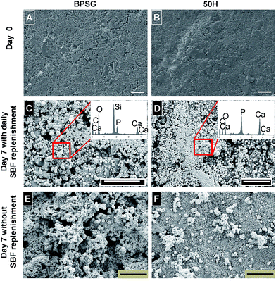
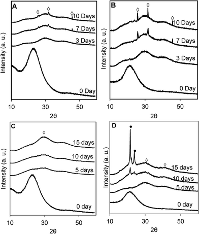
SEM images of BPSG and 50H surface before and after incubation with SBF for 7 days are shown in Fig. 6. Before incubation in SBF, BPSG and PCL–BPSG hybrid exhibited smooth surfaces. After incubation for 7 days both BPSG and PCL–BPSG surfaces were covered by spherical hydroxyapatite particles. Interestingly, when incubation with SBF was done without refreshing the solution, BPSG surface became porous and displayed very rough morphology which may be due to bulk degradation of the pure glass after incubation in SBF (Fig. 6E). In contrast, 50H had smooth surface even after incubation in SBF for 7 days without solution refreshment likely to be the result of the slower degrading PCL compensating the faster degradation of the glass in the hybrid material. The Ca/P ratio for the BPSG and 50H calculated from EDX spectra (Fig. 6C and D insets) showed 1.55 ± 0.03 and 1.71 ± 0.04 respectively suggesting that higher amount of calcium deposited as hydroxyapatite in the hybrid 50H. Since pure hydroxyapatite has a Ca/P ratio of 1.67, our data on 50H matches this stoichiometric ratio indicating the utility of boron-based hybrid biomaterials.The XRD patterns of BPSG and 50H after incubating in SBF for 3, 7 and 10 days (Fig. 7) showed the deposition of low crystalline hydroxyapatite within the first 3 days. After 7 and 10 days of incubation, however, strong hydroxyapatite peaks (2θ = 25.9, 31.77 and 45.40) were observed indicating that both the control BPSG glass and the hybrid materials were bioactive. Consistent with our SEM images (Fig. 6C and D), we observed considerably dense layer of hydroxyapatite in the samples with daily SBF refreshment (Fig. 7A and B). Without daily SBF refreshment, the PCL peaks were detected (Fig. 7D; 2θ = 21.5, and 22.10) since the low molecular weigh PCL released during the hydroxyapatite formation remained on the surface. This study demonstrated, for the first time, the chemical reactivity of calcium free BPSG and PCL–BPSG hybrids and their ability to deposit hydroxyapatite when incubated in SBF. The present study is also the first to incorporate B2O3 as a glass component in class II organic–inorganic hybrids. The presence of B2O3 prevents the formation of silica rich layer which is known to cause discontinuous release of metal ions from glass and formation of hydroxyapatite20,26,27 while accelerating bulk degradation of the glass matrix.26 When the BPSG is bonded to a polymer to produce a class II hybrid, its subsequent degradation and formation of hydroxyapatite could be controlled by controlling the polymer content in the hybrid and the B2O3 in the glass. Thus the presence of B2O3 into the current PCL–BPSG hybrid matrix could enhance continuous degradation and dissolution of components as well as the formation of hydroxyapatite.
3.6 Porous 3D scaffolds from class II PCL–BPSG hybrid biomaterials
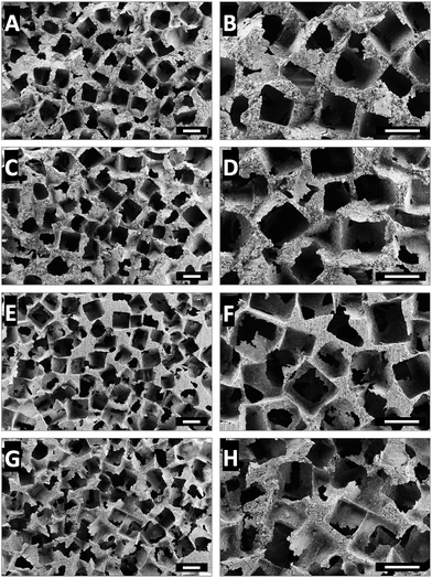
Processability into 3D porous scaffolds is an important requirement for a hybrid organic–inorganic biomaterial for bone tissue engineering and regeneration applications. Electrospinning is by far the most widely used technique to fabricate scaffolds from hybrid organic–inorganic biomaterials.15,38 However, the small pore sizes inherent to electrospun scaffolds limits cellular infiltration.39 Another approach reported is foaming using surfactants but this approach often yields ill-defined pores with poor pore interconnectivity.40,41 The use of organic solvents or surfactants is also not desired since their post-fabrication complete removal is a challenge. In the current work, we have developed a solvent-free casting and particulate leaching method and fabricated well-defined and highly porous PCL–BPSG hybrid scaffolds (Fig. 8). Contrary to the method of solid-state gas foaming which resulted in isolated pores,42,43 our scaffolds were fully interconnected suggesting their utility as ideal scaffolds for bone tissue engineering.4. Conclusions
PCL–BPSG class II hybrid biomaterials were successfully synthesized via a non-aqueous sol–gel process. The PCL chains were successfully end-capped by trimethoxysilane functional groups and underwent carboxylation and condensation with glass precursors to form a single-phase organic–inorganic matrix. Solid-state 29Si-NMR studies revealed that the hybrid materials possessed covalent bonding between PCL and BPSG phases. The SEM/EDX and XPS results revealed homogeneity of the hybrid system and the elemental analyses result indicated that all the elements were incorporated successfully. Hydroxyapatite deposition was observed on the hybrid materials and 3D porous scaffolds were successfully fabricated. Taken together, the synthesized hybrid materials could be potential candidates for bone tissue engineering applications.Acknowledgements
DM acknowledge the financial support of the Vanier Canada Graduate Scholarship. This work is supported by the Natural Science and Engineering Research Council (NSERC) of Canada.References
- S. Bose, M. Roy and A. Bandyopadhyay, Trends Biotechnol., 2012, 30, 546–554 CrossRef CAS PubMed.
- D. W. Hutmacher, Biomaterials, 2000, 21, 2529–2543 CrossRef CAS PubMed.
- F. J. O'Brien, Mater. Today, 2011, 14, 88–95 CrossRef.
- J. R. Jones, Acta Biomater., 2013, 9, 4457–4486 CrossRef CAS PubMed.
- T. Niemelä, H. Niiranen, M. Kellomäki and P. Törmälä, Acta Biomater., 2005, 1, 235–242 CrossRef PubMed.
- K. Rezwan, Q. Z. Chen, J. J. Blaker and A. R. Boccaccini, Biomaterials, 2006, 27, 3413–3431 CrossRef CAS PubMed.
- G. Kickelbick, Indroduction to Hybrid Materials, Wiley-VCH Verlag GmbH & Co. KGaA, 2006, pp. 1–48 Search PubMed.
- B. M. Novak, Adv. Mater., 1993, 5, 422–433 CrossRef CAS.
- J. Wen and G. L. Wilkes, Chem. Mater., 1996, 8, 1667–1681 CrossRef CAS.
- Y. Shirosaki, K. Tsuru, S. Hayakawa, A. Osaka, M. A. Lopes, J. D. Santos, M. A. Costa and M. H. Fernandes, Acta Biomater., 2009, 5, 346–355 CrossRef CAS PubMed.
- L. Ren, K. Tsuru, S. Hayakawa and A. Osaka, J. Non-Cryst. Solids, 2001, 285, 116–122 CrossRef CAS.
- M. M. Pereira, J. R. Jones, R. L. Orefice and L. L. Hench, J. Mater. Sci.: Mater. Med., 2005, 16, 1045–1050 CrossRef CAS PubMed.
- S. G. Viviane, Z. Alessandra, M. O. Natalia, M. G. Alfredo, S. Rogéria and M. P. Marivalda, Biomed. Mater., 2012, 7, 015004 CrossRef PubMed.
- E. M. Valliant, F. Romer, D. Wang, D. S. McPhail, M. E. Smith, J. V. Hanna and J. R. Jones, Acta Biomater., 2013, 9, 7662–7671 CrossRef CAS PubMed.
- B. A. Allo, A. S. Rizkalla and K. Mequanint, Langmuir, 2010, 26, 18340–18348 CrossRef CAS PubMed.
- S.-H. Rhee, J.-Y. Choi and H.-M. Kim, Biomaterials, 2002, 23, 4915–4921 CrossRef CAS PubMed.
- I. Bilecka and M. Niederberger, Electrochim. Acta, 2010, 55, 7717–7725 CrossRef CAS.
- J. N. Hay and H. M. Raval, Chem. Mater., 2001, 13, 3396–3403 CrossRef CAS.
- A. Vioux, Chem. Mater., 1997, 9, 2292–2299 CrossRef.
- G. Kaur, O. P. Pandey, K. Singh, D. Homa, B. Scott and G. Pickrell, J. Biomed. Mater. Res., Part A, 2014, 102, 254–274 CrossRef PubMed.
- A. Yao, D. Wang, W. Huang, Q. Fu, M. N. Rahaman and D. E. Day, J. Am. Ceram. Soc., 2007, 90, 303–306 CrossRef CAS.
- Q. Fu, M. N. Rahaman, B. S. Bal, L. F. Bonewald, K. Kuroki and R. F. Brown, J. Biomed. Mater. Res., Part A, 2010, 95, 172–179 CrossRef PubMed.
- Y. Gu, G. Wang, X. Zhang, Y. Zhang, C. Zhang, X. Liu, M. N. Rahaman, W. Huang and H. Pan, Mater. Sci. Eng., C, 2014, 36, 294–300 CrossRef CAS PubMed.
- J. Ning, A. Yao, D. Wang, W. Huang, H. Fu, X. Liu, X. Jiang and X. Zhang, Mater. Lett., 2007, 61, 5223–5226 CrossRef CAS.
- C. Wu, R. Miron, A. Sculean, S. Kaskel, T. Doert, R. Schulze and Y. Zhang, Biomaterials, 2011, 32, 7068–7078 CrossRef CAS PubMed.
- M. N. Rahaman, D. E. Day, B. Sonny Bal, Q. Fu, S. B. Jung, L. F. Bonewald and A. P. Tomsia, Acta Biomater., 2011, 7, 2355–2373 CrossRef CAS PubMed.
- S. Xu, X. Yang, X. Chen, H. Shao, Y. He, L. Zhang, G. Yang and Z. Gou, J. Non-Cryst. Solids, 2014, 405, 91–99 CrossRef CAS.
- T. Kokubo and H. Takadama, Biomaterials, 2006, 27, 2907–2915 CrossRef CAS PubMed.
- L. Shechter and J. Wynstra, Ind. Eng. Chem., 1956, 48, 86–93 CrossRef CAS.
- D. P. Debecker and P. H. Mutin, Chem. Soc. Rev., 2012, 41, 3624–3650 RSC.
- M. Niederberger, Acc. Chem. Res., 2007, 40, 793–800 CrossRef CAS PubMed.
- L. Viau, M.-A. Néouze, C. Biolley, S. Volland, D. Brevet, P. Gaveau, P. Dieudonné, A. Galarneau and A. Vioux, Chem. Mater., 2012, 24, 3128–3134 CrossRef CAS.
- B. Karmakar, G. De, D. Kundu and D. Ganguli, J. Non-Cryst. Solids, 1991, 135, 29–36 CrossRef CAS.
- C. Sanchez, J. Livage, M. Henry and F. Babonneau, J. Non-Cryst. Solids, 1988, 100, 65–76 CrossRef CAS.
- K. Sharp, J. Sol-Gel Sci. Technol., 1994, 2, 35–41 CrossRef CAS.
- K. J. MacKenzie and M. E. Smith, Multinuclear Solid State NMR of Inorganic Materials, Pergamon, 2002 Search PubMed.
- H. Bittiger, R. H. Marchessault and W. D. Niegisch, Acta Crystallogr., Sect. B: Struct. Crystallogr. Cryst. Chem., 1970, 26, 1923–1927 CrossRef CAS.
- H. W. Kim, H. E. Kim and J. C. Knowles, Adv. Funct. Mater., 2006, 16, 1529–1535 CrossRef CAS.
- J. Nam, Y. Huang, S. Agarwal and J. Lannutti, Tissue Eng., 2007, 13, 2249–2257 CrossRef CAS PubMed.
- O. Mahony, O. Tsigkou, C. Ionescu, C. Minelli, L. Ling, R. Hanly, M. E. Smith, M. M. Stevens and J. R. Jones, Adv. Funct. Mater., 2010, 20, 3835–3845 CrossRef CAS.
- J. R. Jones, L. M. Ehrenfried and L. L. Hench, Biomaterials, 2006, 27, 964–973 CrossRef CAS PubMed.
- C. C. Zhou, L. Ma, W. Li and D. G. Yao, Biofabrication, 2011, 3, 045003 CrossRef PubMed.
- L. Ma, W. Jiang and W. Li, Int. J. Polym. Mater., 2014, 63, 510–517 CrossRef CAS PubMed.
Footnote |
| † Electronic supplementary information (ESI) available. See DOI: 10.1039/c6ra08339k |
| This journal is © The Royal Society of Chemistry 2016 |

