
An enhanced oxygen electrode catalyst by incorporating CoO/SnO2 nanoparticles in crumpled nitrogen-doped graphene in alkaline media†
Xiu-Xiu Ma and
Xing-Quan He*
School of Materials Science and Engineering, Changchun University of Science and Technology, Changchun 130022, P. R. China. E-mail: hexingquan@hotmail.com; Tel: +86-431-85583430
First published on 11th May 2016
Abstract
To address issues concerning energy consumption and the environment, it is of great importance to design a highly efficient, durable and inexpensive oxygen electrode for energy storage and conversion devices. In this work, CoO/SnO2 nanoparticles were successfully incorporated in nitrogen-doped graphene by a facile method. The composite was of porous structure, and exhibited efficient bifunctional activity and outstanding stability towards both oxygen reduction reaction (ORR) and oxygen evolution reaction (OER). For ORR, the catalyst favored a direct four-electron-transfer pathway, and produced kinetic current density values close to those of Pt/C. In addition, for OER, it achieved a lower overpotential at a current density of 10 mA cm−2 and a smaller Tafel slope than RuO2. What is more, the value of the potential difference ΔE(OER–ORR), a measure of the overall bifunctionality of the catalyst, was 0.72 V, comparable with the values for state-of-the-art nonprecious bifunctional catalysts. The remarkable bifunctional activity of the catalyst was mainly attributed to the synergistic effects between metal oxides and nitrogen-doped graphene.
1. Introduction
Owing to their high efficiency, environmental friendliness and convenience, new energy resources have attracted intensive attention in order to protect the ecological environment and build a harmonious society. The oxygen reduction reaction (ORR) and oxygen evolution reaction (OER) play decisive roles in oxygen reaction-based regenerative energy storage and conversion devices, including metal–air batteries, and water-splitting and fuel cells.1–5 So far, Pt/C and RuO2 have been recognized as the most efficient ORR and OER catalysts,6,7 respectively. However, the scarcity and high cost of the noble metals hamper their large scale application. Therefore, it is desirable to develop highly efficient and low-cost nonprecious bifunctional catalysts as alternatives to noble metal catalysts.Recently, various nonmetal and nonprecious metal materials have been reported as effective oxygen electrode catalysts, including heteroatom-doped carbon,8–11 transition metal composites,2,12–18 spinel materials,19,20 perovskite materials,4,21–23 and so on. Investigations revealed nitrogen-doped carbon afforded distinct ORR/OER performance10,24–27 because nitrogen intrinsically created polarization in the carbon framework, configurated defects, and induced active sites.24,28 In addition, the transition metal composites/nitrogen-doped carbon hybrids achieved attractive bifunctional performance, mainly due to electronic coupling between transition metal and carbon, and to synergistic effects.1,29,30 Cobalt-based materials, such as porous Co3O4,31,32 plate-formed Co(OH)2,33 porous CoS2,34 Co2P3![[thin space (1/6-em)]](https://www.rsc.org/images/entities/char_2009.gif) 35 and so on, were promising since these materials gave a reasonable balance between storage, cost, activity and durability. Particularly, CoO nanoparticles which were of a diversity of morphologies exhibited good ORR36–38 and superior OER performance1,38 due to their mesoporous structure, large surface area, and the highly active surface containing Co2+ with oxygen vacancies.1,36–38 When CoO nanoparticles were supported on N–carbon, the ORR and OER performance was greatly improved.1,14,39 Additionally, tin oxide (SnO2) itself was of inherently abundant oxygen vacancy defects and a variety of valance states of Sn,40 so that long-term durability and kinetic stability could be obtained when tin oxide with very high surface energy was modified with metal oxides and conductive templates.41–43 Thus, SnO2/graphene connected to CoO could be efficient as an oxygen electrode catalyst; however, as far as we know, there are few previous reports in this respect.
35 and so on, were promising since these materials gave a reasonable balance between storage, cost, activity and durability. Particularly, CoO nanoparticles which were of a diversity of morphologies exhibited good ORR36–38 and superior OER performance1,38 due to their mesoporous structure, large surface area, and the highly active surface containing Co2+ with oxygen vacancies.1,36–38 When CoO nanoparticles were supported on N–carbon, the ORR and OER performance was greatly improved.1,14,39 Additionally, tin oxide (SnO2) itself was of inherently abundant oxygen vacancy defects and a variety of valance states of Sn,40 so that long-term durability and kinetic stability could be obtained when tin oxide with very high surface energy was modified with metal oxides and conductive templates.41–43 Thus, SnO2/graphene connected to CoO could be efficient as an oxygen electrode catalyst; however, as far as we know, there are few previous reports in this respect.
In view of this, we prepared a hybrid of CoO and nitrogen-doped graphene-supported tin oxide by a facile method. In this material, the 3d orbitals of tin opened up the possibility of redistribution of electron density, resulting in the easy formation of oxygen vacancies, which play a critical role in catalyzing the OER.44 As a consequence, the hybrid exhibited excellent ORR and OER performance – a quick four-electron-transfer pathway, a kinetic current density close to that of Pt/C, and a favorable kinetic process in the ORR. What is more, it achieved a similar overpotential (285 mV vs. saturated calomel electrode (SCE) at a current density of 10 mA cm−2) to RuO2 in the OER. At the same time, the hybrid avoided the common problem of poor durability of carbon–transition-metal catalysts under corrosive conditions. The remarkable bifunctional performance mainly resulted from the porous structure with high specific surface area, which facilitated quick electron and mass transfer, and the synergistic effects between metal oxides and nitrogen-doped graphene. As far as we know, this is the first report on cobalt monoxide and tin oxide dispersed in nitrogen-doped graphene as an efficient oxygen electrode catalyst.
2. Experimental
2.1. Materials
Graphite powder was obtained from Sinopharm Chemical Reagent Co., Ltd. Commercial platinum/carbon (Pt/C) (20 wt% Pt on Vulcan XC-72) was purchased from Alfa Aesar. Both ruthenium(IV) oxide and 5% Nafion were obtained from Sigma. All other chemical reagents, including H2SO4 (98%), KOH, KMnO4, Na2SO4, melamine, cobalt(II) acetate tetrahydrate and tin(II) chloride dehydrate, were analytically pure and were employed directly as received. Distilled water was used throughout the whole experiment.2.2. Decorating nitrogen-doped graphene with cobalt monoxide and tin oxide
Graphene oxide (GO) was first prepared using the modified Hummers' method.45 Then, 400 mg of GO was dispersed in 50 mL of mixed ethylene glycol and distilled water, where the volume ratio of ethylene glycol to distilled water was 9:1. To fabricate the final catalyst, a facile method was employed that used a combination of hydrothermal treatment and pyrolysis. In a typical process, 0.14 mmol of SnCl2·2H2O, 0.35 mmol of Co(OAc)2·4H2O, 1.07 mmol of C3H6N6, 0.55 mmol of Na2SO4, 6.2 mL of the above GO dispersion, and 0.5 mL of ethylene glycol were dissolved in 20 mL of distilled water and vigorously stirred at 70 °C for 6 h. Herein, the epoxide in graphene promoted the hydrolysis of SnCl2·2H2O and accelerated the condensation of Sn(OH)4, which further crosslinked together and yielded a homogenous mixture in a GO dispersion under strong stirring.46 Then the mixture was transferred to a 50 mL Teflon-lined stainless autoclave, with the addition of NH3·H2O to adjust the pH to ∼12, and heated at 180 °C for 12 h, forming a black precipitate. After that, the wet aggregate was washed with distilled water several times until the pH was neutral, and dried in a vacuum oven at 35 °C overnight. The product was recorded as CoO/SnO2/NG. Afterwards, the black material was placed in the center of a tube furnace, and heated to 300 °C at a rate of 5 °C min−1, which was then increased to 500 °C at 10 °C min−1, and calcined for 2 h in an argon atmosphere. The powder was labeled CoO/SnO2/NG-500. For comparison, CoO/SnO2/NG-600 and CoO/SnO2/NG-700 were prepared. CoO/NG-500, SnO2/NG-500, NG-500 and r-GO-500 were also obtained by a similar procedure, only with the absence of SnCl2·2H2O, Co(OAc)2·4H2O, SnCl2·2H2O and Co(OAc)2·4H2O, and SnCl2·2H2O and Co(OAc)2·4H2O and NH3·H2O, respectively.
2.3. Morphology and structure characterization
The morphology and structure of the as-synthesized samples were characterized by scanning electron microscopy (SEM; JSM-6701F, operating at 5 kV) and transmission electron microscopy (TEM; Tecnai G2 20 S-Twin, operated at 200 kV). SEM energy-dispersive X-ray (EDX) mapping was conducted on a focused ion beam scanning electron microscope (EDS Inca X-Max). X-ray diffraction (XRD) powder spectra and nitrogen adsorption–desorption isotherms were measured on a RIGAK X-ray diffractometer (D/MAX2550 VB/PC, Japan) with Cu Kα radiation (λ = 0.15148 nm) and an ASAP2020 volumetric adsorption analyzer at 77 K, respectively. The Raman spectra were measured using a TriVista™ 555CRS Raman spectrometer at 532 nm. X-ray photoelectron spectroscopy (XPS) was done on an ESCLAB 250 spectrometer using Al Kα as the exciting source (1486.6 eV photons), and the C 1s peak at 284.6 eV as a reference.2.4. Electrochemical characterization
All electrochemical measurements were taken in a standard three-electrode cell system on a CHI 660E electrochemical workstation, where a catalyst-modified glassy carbon electrode was used as working electrode, a saturated calomel electrode (SCE) functioned as the reference electrode and a platinum wire acted as a counter electrode. All electrochemical testing was performed with a Pine Instrument Company AF-MSRCE modulator speed rotator. The tests were carried out in O2/N2-saturated 0.1 M KOH solution for ORR with a rotating disk electrode (RDE, d = 5 mm) and ring rotating disk electrode (RRDE, d = 5.61 mm), and O2-saturated 1 M KOH electrolyte for OER with the with a rotation speed of 1600 rpm and a scan rate of 10 mV s−1. The working electrode was prepared as follows. In general, 6 mg of electrocatalyst was ultrasonically dispersed in 3 mL of solution comprising 2.8 mL of ethyl alcohol and 0.2 mL of Nafion, forming a homogeneous ink, followed by pipetting a certain amount of the ink onto the surface of a glassy carbon electrode. The catalyst loading per area was kept to 0.28 mg cm−2 and all electrochemical measurements were performed three times to avoid any incidental errors. All potentials are reported versus (vs.) the saturated calomel electrode (SCE).3. Results and discussion
3.1. Composition and morphology characterizations of the catalyst
XRD was used to characterize the crystallinity of the samples. As shown in Fig. 1a, r-GO-500 (002), (103), (107), (511) and (200) diffraction peaks were located at 26.1°, 43.2°, 48.8°, 50.3° and 54.5°, respectively. The broad peak at 2θ ∼ 26.1° suggested the reduction of GO. After nitrogen doping (NG-500), the diffraction peaks at 26.2°, 43.4° and 55.7° fitted well to NG-500 (002), (103) and (108), respectively. Fig. S1a† depicts that the diffraction peaks at 34.1°, 51.8°, and 65.7° in the SnO2/NG-500 sample were indexed to SnO2 (101), (201) and (310), respectively. In addition, the Sn (111) diffraction peak centered at 32.3° was observed in SnO2/NG-500 (Fig. S1a†), formed by the reduction of SnO2 via contact with graphene sheets during the calcination process.47 The presence of Sn was very important in order to derive long-term stability.48 And for CoO/NG-500, strong CoO (111), (021), (200), (104), (220) and (204) diffraction peaks appeared at 36.7°, 42.5°, 44.3°, 51.3°, 61.6° and 75.4°, respectively. The intensity of the diffraction peaks corresponding to 2θ ∼ 26° for both SnO2/NG-500 and CoO/NG-500 decreased (Fig. S1a†), which was probably due to the overlapping of SnO2 or the dispersion of CoO on the NG matrix. For CoO/SnO2/NG-500, the characteristic diffraction peak of CoO (200) was located at 44.3°, and the strong XRD peak centered at 51.5°, 62.62° and 75.9° corresponded to SnO2 (201), (223) and (400), respectively. The diffraction peak of SnO2 was shifted to higher angles with narrow half-peak width compared with SnO2/NG-500, indicating the high crystallinity of the hybrid. | ||
| Fig. 1 (a) XRD profiles for 2θ ranging from 10° to 90°; (b) nitrogen absorption–desorption isotherm curve and pore distribution curve (inset); (c) Raman spectra and ID/IG values of CoO/SnO2/NG, CoO/SnO2/NG-500, CoO/NG-500, SnO2/NG-500, NG-500 and r-GO-500; and (d) enlargement of the rectangular area outlined in (c). | ||
Catalytic reactions often occur on the surface of catalysts, and the reaction rate is typically related to the surface area.49 The nitrogen adsorption isotherm for CoO/SnO2/NG-500 revealed a typical-IV type curve with an obvious hysteresis loop (Fig. 1b), and the pore size distribution curve inset in Fig. 1b indicates a mesoporous and macroporous structure. The average pore width of CoO/SnO2/NG-500 was 45.1 nm. The nitrogen adsorption–desorption isotherm and the pore size distribution curves for CoO/NG-500, SnO2/NG-500, NG-500 and r-GO-500 are given for comparison; see Fig. S1b–e.† The surface area values were 509.4, 359.7, 173.5, 195.5 and 282.2 cm2 g−1 for r-GO-500, NG-500, CoO/NG-500, SnO2/NG-500 and CoO/SnO2/NG-500 (see Table S1†), respectively, and the average pore sizes are shown in Fig. S1f and Table S1.† The higher BET (Brunauer–Emmett–Teller) surface area of CoO/SnO2/NG-500 compared with CoO/NG-500 and SnO2/NG-500 was mainly ascribed to the strong interaction between cations preventing condensation and precipitation of mixed metal oxides,41 exposing more active sites, which would be favorable for the transfer of electrolyte and oxygen molecules during oxygen catalysis.9,50
Raman spectra (Fig. 1c) exhibited typical D bands at around 1339 cm−1, attributed to the structure defects in the graphene plane, and G bands at around 1589 cm−1, assigned to the sp2 carbon in all of the samples. As shown in Fig. 1c, the ID/IG values apparently were higher for NG-500 (1.13), SnO2/NG-500 (1.26), CoO/NG-500 (1.08), CoO/SnO2/NG (1.12) and CoO/SnO2/NG-500 (1.16) than for r-GO-500 (1.04), revealing an increased number defects in the graphene structure after nitrogen and metal oxide doping. Additionally, the ID/IG value of CoO/SnO2/NG-500 was higher than that of CoO/SnO2/NG, attributed to the increased vacancies in the graphene planes and defects at the edges after heat decomposition.51 In addition, CoO/SnO2/NG-500 displayed two bands located at 640 and 482 cm−1 stronger than those of CoO/NG-500 and SnO2/NG-500 (Fig. 1d), attributed to A1g and Eg, respectively. The A1g and Eg were Raman-active, and the Eg band (482 cm−1) indicated the vibration of oxygen, representing the oxygen defects in the Raman spectrum.1,41 The oxygen vacancies could increase the number of active defects, which is beneficial for oxygen catalysis.1,44
The morphology and structure of the samples were characterized by scanning electron microscopy (SEM) and transmission electron microscopy (TEM). The SEM micrograph in Fig. 2a shows more distinct crumples in NG-500 than in r-GO-500 (Fig. S2a†), representing more defective sites in NG-500. The high number of defects could also be observed in the TEM image (Fig. 2c). For the CoO/NG-500 and SnO2/NG-500 samples, CoO and SnO2 nanoparticles closely covered the surface of NG (Fig. S2b and c†). Fig. 2b shows that CoO/SnO2 nanoparticles were anchored on the NG matrix in the CoO/SnO2/NG-500 composite. What is more, the energy-dispersive X-ray (EDX) mapping in Fig. S2d–i† shows that cobalt, tin, nitrogen, oxygen and carbon atoms were distributed uniformly. At the same time, TEM images demonstrated that CoO and SnO2 were successfully loaded on NG, and distinct crystal lattice fringes with interplanar distances of 2.4 and 1.8 Å correspond to the (200) plane of CoO and (201) plane of SnO2 (inset in Fig. 2d), respectively.
 | ||
| Fig. 2 (a and b) SEM images of NG-500 (a) and CoO/SnO2/NG-500 (b), and (c and d) TEM images of NG-500 (c) and CoO/SnO2/NG-500 (d). Insets in (d) show HRTEM images of CoO and SnO2. | ||
Information about the surface chemical composition was gained by XPS. Fig. 3a reveals the signals of Co, Sn and N in CoO/SnO2/NG-500, demonstrating the successful doping of the three elements into the graphene matrix. The contents of Co, Sn, N, O and C in CoO/SnO2/NG-500 were determined to be 8.0, 7.8, 3.8, 27.0 and 53.4 at% (see Table 1), respectively. After doping, the C content in r-GO-500 was greatly reduced, as presented in Table 1. The high-resolution XPS spectra shed light on the bonding configuration of each component. As exhibited in Fig. 3b, the C 1s spectrum was deconvoluted into three peaks at 284.65, 286.1 and 288.25 eV, corresponding to sp2 carbon, C![[double bond, length as m-dash]](https://www.rsc.org/images/entities/char_e001.gif) N & C–O and C–N & CO, respectively.24,52 The high peak intensity at 284.65 eV indicated the sp2 nature of graphene in the composite. The O 1s peaks centered at 530.1, 530.75, 531.6, 532.45 and 533.45 eV were attributed to Sn–O, C–O, C(O)O, Co–O and O–H, respectively (see Fig. 3c).53 As seen from Fig. 3d, the N 1s peaks demonstrated the formation of pyrrolic N (398.65 eV, 2.1 at%) and pyridinic N (400.1 eV, 1.7 at%). Nitrogen doping could enhance the conductivity of the graphene sheets, and pyrridic-like defects could facilitate electrolyte penetration into the graphene, and lead to a positive shift of the onset potential for ORR.9,50,54 Therefore, nitrogen doping was beneficial for oxygen catalysis.9,24,28 The peak located at 780.8 eV was fitted to Co2+, and the shake peaks at 786.2, 796.8 and 802.9 eV (Fig. 3e) further demonstrated the existence of Co2+.55 As shown in Fig. 3f, the two peaks in the high resolution Sn 3d XPS spectrum were symmetric; Sn 3d5/2 appeared at 487.3 eV and Sn 3d3/2 at 495.2 eV, confirming the presence of Sn4+.46,56 The high valence state of the tin ion (Sn4+) in the tin oxide created strong stabilizing effects.41,57 Additionally, the Sn 3d5/2 peak in SnO2/NG-500 was located at 486.9 eV, and the Co2+ peak in CoO/NG-500 was at 780.2 eV (Fig. S3a and b†). The positive shifts of Sn 3d5/2 and Co2+ in CoO/SnO2/NG-500 relative to SnO2/NG-500 and CoO/NG-500 indicated interaction between SnO2 and CoO. What is more, the ΔBEO–Sn (binding energy difference between O and Sn) of CoO/SnO2/NG-500 was significantly reduced compared with that of SnO2/NG-500 (Table S2†), further suggesting strong electronic coupling effects between SnO and anchored CoO.41
N & C–O and C–N & CO, respectively.24,52 The high peak intensity at 284.65 eV indicated the sp2 nature of graphene in the composite. The O 1s peaks centered at 530.1, 530.75, 531.6, 532.45 and 533.45 eV were attributed to Sn–O, C–O, C(O)O, Co–O and O–H, respectively (see Fig. 3c).53 As seen from Fig. 3d, the N 1s peaks demonstrated the formation of pyrrolic N (398.65 eV, 2.1 at%) and pyridinic N (400.1 eV, 1.7 at%). Nitrogen doping could enhance the conductivity of the graphene sheets, and pyrridic-like defects could facilitate electrolyte penetration into the graphene, and lead to a positive shift of the onset potential for ORR.9,50,54 Therefore, nitrogen doping was beneficial for oxygen catalysis.9,24,28 The peak located at 780.8 eV was fitted to Co2+, and the shake peaks at 786.2, 796.8 and 802.9 eV (Fig. 3e) further demonstrated the existence of Co2+.55 As shown in Fig. 3f, the two peaks in the high resolution Sn 3d XPS spectrum were symmetric; Sn 3d5/2 appeared at 487.3 eV and Sn 3d3/2 at 495.2 eV, confirming the presence of Sn4+.46,56 The high valence state of the tin ion (Sn4+) in the tin oxide created strong stabilizing effects.41,57 Additionally, the Sn 3d5/2 peak in SnO2/NG-500 was located at 486.9 eV, and the Co2+ peak in CoO/NG-500 was at 780.2 eV (Fig. S3a and b†). The positive shifts of Sn 3d5/2 and Co2+ in CoO/SnO2/NG-500 relative to SnO2/NG-500 and CoO/NG-500 indicated interaction between SnO2 and CoO. What is more, the ΔBEO–Sn (binding energy difference between O and Sn) of CoO/SnO2/NG-500 was significantly reduced compared with that of SnO2/NG-500 (Table S2†), further suggesting strong electronic coupling effects between SnO and anchored CoO.41
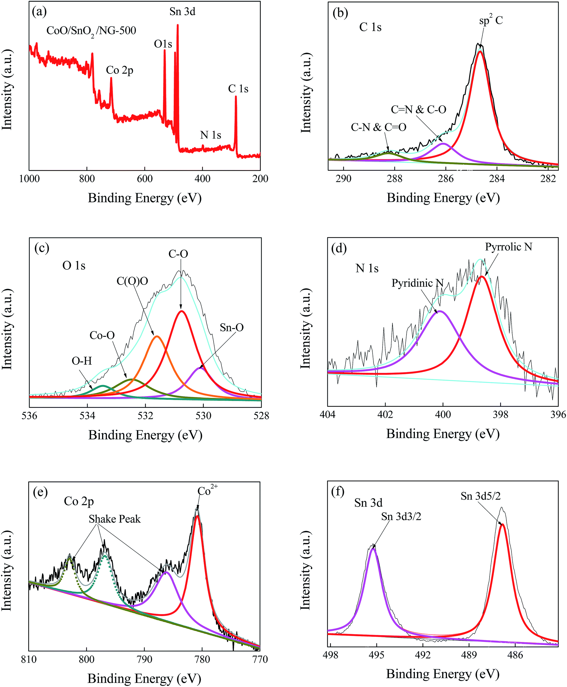 | ||
| Fig. 3 (a) XPS spectrum of CoO/SnO2/NG-500, and (b–f) high resolution XPS spectra of C 1s (b), O 1s (c), N 1s (d), Co 2p (e) and Sn 3d (f). | ||
| Material | C 1s (%) | O 1s (%) | N 1s (%) | Co 2p(%) | Sn 3d(%) |
|---|---|---|---|---|---|
| CoO/SnO2/NG-500 | 53.4 | 27.0 | 3.8 | 8.0 | 7.8 |
| CoO/SnO2/NG | 51.9 | 27.5 | 9.5 | 7.7 | 3.4 |
| CoO/NG-500 | 41.6 | 36.8 | 1.4 | 20.2 | — |
| SnO2/NG-500 | 60.5 | 24.3 | 4.1 | — | 11.1 |
| NG-500 | 85.9 | 3.3 | 10.8 | — | — |
| r-GO-500 | 90.2 | 9.8 | — | — | — |
3.2. Oxygen reduction reaction activity
The oxygen reduction reaction activity of the catalyst was first evaluated by cyclic voltammetry (CV) measurements. As presented in Fig. 4a, a reduction peak appeared in O2-saturated 0.1 M KOH solution, whereas a featureless plot was observed in O2-free electrolyte, suggesting catalytic activity for CoO/SnO2/NG-500 towards the ORR. To check the effect of calcining temperature on the ORR performance, we also prepared CoO/SnO2/NG by annealing at different temperatures (500, 600 and 700 °C). In Fig. S4a,† CoO/SnO2/NG-500 shows a larger peak current density than CoO/SnO2/NG-600 and CoO/SnO2/NG-700 in the CV measurements, and it achieved the largest limiting current density (JL) and the most positive onset potential (Eonset) in the linear sweep voltammetry (LSV) polarization curves (Fig. S4b†), demonstrating a pronounced ORR catalytic activity for CoO/SnO2/NG-500. Consequently, the following tests were taken on the CoO/SnO2/NG-500 catalyst. LSV measurements were conducted for the samples using a rotating disk electrode at 1600 rpm and 10 mV s−1 in 0.1 M KOH, as shown in Fig. 4b. It can be seen that the polarization curve of r-GO-500 exhibited an onset potential of −0.122 V vs. SCE, whereas NG-500 displayed the onset potential of −0.116 V vs. SCE, which was about 6 mV positive compared with that of r-GO-500, confirming the effect of nitrogen doping on the ORR. Additionally, CoO/SnO2/NG-500 displayed the largest JL (5.77 mA cm−2), the most positive half-wave potential (E1/2 ∼ −0.147 V vs. SCE, only 10 mV more negative than that of Pt/C; thus ΔE1/2 ∼ 10 mV) and the largest kinetic current density (JK: 22.11 mA cm−2) compared with CoO/NG-500 and SnO2/NG-500 (Fig. 4b and c and Table 2), implying the existence of synergistic effects between CoO/SnO2 nanocrystals and NG. The smaller Tafel slope of CoO/SnO2/NG-500 (33 mV dec−1) than of Pt/C (51 mV dec−1) (Fig. 4d and Table 1) indicated its intrinsically favorable kinetic process. The value of the Tafel slope of CoO/SnO2/NG-500 was comparable with those of recently reported state-of-the-art bifunctional catalysts, such as Co(OH)x–NCNT (54 mV dec−1),15 CoS2(400)/N,S-GO (75 mV dec−1),16 NCG–CoO (48 mV dec−1)58 and so on (see Table S3†). | ||
| Fig. 4 (a) Cyclic voltammograms of CoO/SnO2/NG-500 in O2/N2-saturated 0.1 M KOH solution at a scan rate of 10 mV s−1; (b and c) linear sweep voltammograms (b) and kinetic current density (c) of various catalysts; (d) Tafel plots of CoO/SnO2/NG-500 and Pt/C; (e) rotating ring disk electrode tests; (f and g) calculated electron transfer number per oxygen molecule (f) and the HO2− yield (g) of various catalysts; (h) current–time curves of CoO/SnO2/NG-500 and Pt/C at −0.27 V at 1600 rpm after 5 h. | ||
| Sample | Eonset (V vs. SCE) | E1/2 (V vs. SCE) | JL (mA cm−2) | Tafel slope (mV dec−1) | JK (mA cm−2) |
|---|---|---|---|---|---|
| CoO/SnO2/NG-500 | −0.045 | −0.147 | 5.77 | 33 | 22.11 |
| CoO/NG-500 | −0.118 | −0.237 | 4.68 | 78 | 12.90 |
| SnO2/NG-500 | −0.120 | −0.267 | 4.00 | 64 | 11.21 |
| NG-500 | −0.116 | −0.254 | 3.56 | 83 | 7.75 |
| r-GO-500 | −0.122 | −0.231 | 2.47 | 91 | 6.53 |
| 20 wt% Pt/C | 0.020 | −0.137 | 6.39 | 51 | 27.13 |
To gain insight into the ORR kinetics for CoO/SnO2/NG-500, rotating disk electrode (RDE) measurements were performed at rotation speeds ranging from 200 to 2500 rpm, and the corresponding LSV polarization curves obtained are shown in Fig. S4c.† Increasing limiting current densities were observed with the increasing rotation speeds due to the shortened diffusion distance at high rotating speeds.9,17,29 In Fig. S4d,† the Koutecky–Levich (K–L) plots at various potentials exhibited good linearity and the fitting lines were almost parallel, suggesting first-order reaction kinetics and similar electron-transfer numbers (n) per oxygen molecule at different potentials.9,17,29 The n value for CoO/SnO2/NG-500 varied from 3.89 to 3.98 according to the K–L plots in a potential range of −0.24 to −0.72 V vs. SCE (Fig. S4e†),9,17 implying that oxygen was directly reduced to water via a four-electron pathway with high efficiency,9,17,24,25 similar to that for Pt/C.
To further reveal the ORR catalytic mechanism, rotating ring disk electrode measurements were taken in O2-saturated 0.1 M KOH solution at 1600 rpm and 10 mV s−1 at a polarization potential of 0.2 V vs. SCE (Fig. 4e). The LSV polarization curve of CoO/SnO2/NG-500 resembled that of Pt/C, suggesting a similar mechanism for the two catalysts in the ORR.29 CoO/SnO2/NG-500 presented a larger disk JL and a more positive onset potential than those of CoO/NG-500, SnO2/NG-500, NG-500 and r-GO-500, in accordance with the LSV results (Fig. 4b). The electron transfer number per oxygen molecule and HO2− yield were calculated from the following equations according to the disk and ring polarization curves:17
 | (1) |
 | (2) |
The results are presented in Fig. 4f and g. r-GO-500 had a low n value (3.1) and a high HO2− yield (∼45%) (Fig. 4f and g), suggesting r-GO-500 facilitated a 2 + 4 electron-transfer route for the ORR.24,25 In contrast, the n value for CoO/SnO2/NG-500 was 4.0, indicating it had a four-electron-transfer mechanism in the ORR. The n values for CoO/NG-500, SnO2/NG-500 and NG-500 are also given in Fig. 4f. The HO2− yield (<5%) of CoO/SnO2/NG-500 was lower than that of Pt/C, suggesting the hybrid was of excellent stability under corrosive conditions.59
In order to determine the long-term durability of CoO/SnO2/NG-500, the current–time chronoamperometric response was measured at −0.27 V vs. SCE at 1600 rpm and 10 mV s−1 in O2-saturated 0.1 M KOH over 5 h. Fig. 4h shows that CoO/SnO2/NG-500 retained 97.2% of the initial current after continuous measurements, whereas the current for Pt/C decreased to 67.8%, revealing CoO/SnO2/NG-500 had better long-term stability. The better operational durability of the composite was attributed to the following. First, graphene, serving as the matrix in the catalyst, was stable enough in the corrosive alkaline medium,60 while the active carbon used as the support in the 20% Pt/C sample, by contrast, was not stable in the corrosive conditions. Second, SnO2 in the catalyst had abundant oxygen vacancies, which could adsorb oxygen molecules on the surface, accommodating the volume change during the electrocatalytic process.48 Third, the synergistic coupling effects between metal oxides and the NG substrate not only hindered the aggregation of the metal oxides, but also contributed a lot to the remarkable stability due to the metal–N bonding.42,46,60 The overall remarkable ORR performance for CoO/SnO2/NG-500 mainly arose from the porous structure and nitrogen doping in the composite, which provided a feasible pathway to transfer mass and electrons, the role of oxygen vacancy in SnO2, and the synergistic effects between metal oxides and NG.28,39
3.3. Oxygen evolution reaction evaluation
To further investigate the bifunctional properties of CoO/SnO2/NG-500 as an oxygen electrode catalyst, oxygen evolution reaction measurements were performed in 1 M KOH solution using a rotating disk electrode at 1600 rpm and 10 mV s−1. CoO/NG-500, SnO2/NG-500, NG-500, r-GO-500, Pt/C and RuO2 electrodes were also prepared for comparison. As shown in Fig. 5a, NG-500, r-GO-500 and Pt/C displayed poor OER activities. The OER onset potential of CoO/SnO2/NG-500 in Fig. 5a reached 0.42 V vs. SCE, which was more negative than RuO2 (0.47 V vs. SCE), Pt/C (0.61 V vs. SCE), CoO/NG-500 (0.54 V vs. SCE) and SnO2/NG-500 (0.65 V vs. SCE) (Fig. 5a). The overpotentials (η) at a current density of 10 mA cm−2, a value for solar water-splitting devices,10 were compared for CoO/SnO2/NG-500 and RuO2. CoO/SnO2/NG-500 generated a current density of 10 mA cm−2 at an overpotential of 285 mV, which was lower than RuO2 (331 mV) (Table 3), and comparable with previously reported state-of-the-art catalysts, including CoFe2O4/PANI–MWCNT (314 mV),19 CoSn(OH)6 (274 mV),21 NCG–CoO (334 mV),58 CNCNT (310 mV)61 and so on (see Table S4†). | ||
| Fig. 5 (a) OER linear sweep voltammogram curves of the investigated samples at 1600 rpm and 10 mV s−1; (b) OER Tafel plots of the samples; (c) current–time plot of CoO/SnO2/NG-500 (inset: cycle stability measurements by LSV polarization curves before and after 200 cycles); (d) polarization curve for CoO/SnO2/NG-500 in the whole region of ORR and OER. | ||
The kinetics for oxygen evolution with the composite were examined using Tafel plots (Fig. 5b). The Tafel slope of CoO/SnO2/NG-500 was 41 mV dec−1, lower than RuO2 (71 mV dec−1), CoO/NG-500 (58 mV dec−1), SnO2/NG-500 (68 mV dec−1) and NG-500 (92 mV dec−1). This value was comparable with those of other Co-based OER catalysts, including CoP/rGO (66 mV dec−1),2 NCNT/CoxMn1−xO (40 mV dec−1),3 Co(OH)x–NCNT (36 mV dec−1),15 Co3O4/N-CNT–GNR (44 mV dec−1),18 CoFe2O4/PANI–MWCNT (30.7 mV dec−1),19 CoSe (40 mV dec−1),55 and NCG–CoO (71 mV dec−1),58 suggesting this hybrid was favorable for OER kinetics. Furthermore, the stability of CoO/SnO2/NG-500 as an OER catalyst was evaluated by chronoamperometric response; 90.3% of the original current was retained after 5 h (Fig. 5c), and 83.3% of the initial catalytic current remained after 200 continuous cycles (see the inset in Fig. 5c), implying CoO/SnO2/NG-500 was of outstanding OER durability.
The overall oxygen electrode activity was then assessed by the potential difference of ORR and OER metrics (ΔE = Ej=10 − Ej=−3).12 The OER potential was often measured at a current density of 10 mA cm−2 (Ej=10), and the ORR potential was usually recorded at a current density of −3 mA cm−2 (Ej=−3).33 The smaller the ΔE, the more ideal is the catalyst as a reversible oxygen electrode. Remarkably, the ΔE of CoO/SnO2/NG-500 was 0.72 V (Fig. 5d), much lower than the values for recently reported state-of-the-art bifunctional catalysts, such as Co/N-CNT (ΔE = 0.78 V),12 Fe/C/N (ΔE = 0.76 V),62 and IrO2/C (ΔE = 0.87 V).62 Table 3 shows a detailed comparison of different bifunctional catalysts, further highlighting the superior bicatalytic activity of the CoO/SnO2/NG-500 catalyst. The outstanding and selective catalytic activity and long-term durability of CoO/SnO2/NG-500 in both ORR and OER makes it a promising candidate for the oxygen electrode catalyst in energy storage and conversion devices.
Based on the relationship properties to structure and composition, the superior bifunctional performance of CoO/SnO2/NG-500 should be attributed to the following. First, as shown by its nitrogen adsorption–desorption isotherm, the hybrid was of porous structure and high specific surface area, which facilitated quick mass and electron transfer.48,50 Second, the presence of SnO2 in the composite hindered the aggregation of CoO, and vice versa, supported by the higher specific surface area of CoO/SnO2/NG-500 than those of single metal oxide/NG-500. The larger specific surface area enabled the more exposure of the active sites for the oxygen catalysis reaction. Third, the presence of Sn in the sample offered more active sites for the interfacial adsorption of alkaline electrolyte.42 Owing to the formation of Sn in the composite, SnO2 nanoparticles could anchor closely to the surface of NG by means of N–Sn interaction,42,63 resulting in the outstanding operational stability of the catalyst. At the same time, the Sn nanoparticles prevented the shrinkage of SnO2, thus expanding the contact area between the hybrid and electrolyte, and providing extra active sites.48 In addition, Sn played a role in the highly active OER performance of the sample due to the interconversion of Sn and SnO2 during continuous cycling.46,48,64 Also, both the oxygen vacancies in the composite, confirmed by Raman spectra, and 1.7 at% pyridinic N doping, shown by XPS, afforded more active sites, and resulted in enhanced ORR and OER performance.1,24,44 Last but not least, the synergistic effects between CoO/SnO2 and heteroatom-doped graphene not only facilitated electron transfer, consequently enhancing electrocatalytic activities, but also provided a guarantee for the long-term working stability.
4. Conclusions
In summary, a novel and highly efficient catalyst for use in oxygen electrodes was prepared by introducing CoO and SnO2 into nitrogen-doped porous graphene nanosheets via a ‘green’ method. The fabricated hybrid achieved enhanced ORR and OER performances. The superior properties originated from the porous structure and high specific surface area of the hybrid, oxygen vacancies, heteroatom doping and the strong synergistic effects of the composites. Owing to the ease of the preparation method, inexpensive materials and highly effective oxygen catalytic activity, the catalyst is a promising candidate as oxygen electrode catalyst in energy storage and conversion devices.Acknowledgements
This work was supported by the Nature Science Foundation of China (NSFC-No. 21273024) and Nature Science Foundation of Jinlin Province, China (No. 20160101298 JC).Notes and references
- R. Gao, Z. Y. Li, X. L. Zhang, J. C. Zhang, Z. B. Hu and X. F. Liu, ACS Catal., 2016, 6, 400–406 CrossRef CAS.
- L. Jiao, Y. X. Zhou and H. L. Jiang, Chem. Sci., 2016, 7, 1690–1695 RSC.
- X. Liu, M. Park, M. G. Kim, S. Gupta, X. J. Wang, G. Wu and J. Cho, Nano Energy, 2016, 20, 315–325 CrossRef CAS.
- H. W. Park, D. U. Lee, M. G. Park, R. Ahmed, M. H. Seo, L. F. Nazar and Z. W. Chen, ChemSusChem, 2015, 8, 1058–1065 CrossRef CAS PubMed.
- L. J. Li, C. Liu, G. He, D. L. Fan and A. Manthiram, Energy Environ. Sci., 2015, 8, 3274–3282 CAS.
- N. Jung, H. Shinc, M. Kimd, I. Jang, H. J. Kim, J. H. Jang, H. Kim and S. J. Yoo, Nano Energy, 2015, 17, 152–159 CrossRef CAS.
- V. T. T. Ho, N. G. Nguyen, C. J. Pan, J. H. Cheng, J. Rick, W. N. Su, J. F. Lee, H. S. Sheu and B. J. Hwang, Nano Energy, 2012, 1, 687–695 CrossRef CAS.
- J. T. Zhang and L. M. Dai, ACS Catal., 2015, 5, 7244–7253 CrossRef CAS.
- R. Li, Z. D. Wei and X. L. Gou, ACS Catal., 2015, 5, 4133–4142 CrossRef CAS.
- K. G. Qu, Y. Zheng, S. Dai and S. Z. Qiao, Nano Energy, 2016, 19, 373–381 CrossRef CAS.
- S. Chen, J. J. Duan, Y. Zheng, X. M. Chen, X. W. Du, M. Jaroniec, and S. Z. Qiao, Energy Storage Materials, 2015, vol. 1, pp. 17–24 Search PubMed.
- Y. Y. Liu, H. L. Jiang, Y. H. Zhu, X. L. Yang and C. Z. Li, J. Mater. Chem. A, 2016, 4, 1694–1701 CAS.
- J. X. Xu, Q. M. Yu, C. X. Wu and L. H. Guan, J. Mater. Chem. A, 2015, 3, 21647–21654 CAS.
- Y. Y. Liang, H. L. Wang, P. Diao, W. Chang, G. S. Hong, Y. G. Li, M. Gong, L. M. Xie, J. G. Zhou, J. Wang, T. Z. Regier, F. Wei and H. J. Dai, J. Am. Chem. Soc., 2012, 134, 15849–15857 CrossRef CAS PubMed.
- J. E. Kim, J. Lim, G. Y. Lee, S. H. Choi, U. N. Maiti, W. J. Lee, H. J. Lee and S. O. Kim, ACS Appl. Mater. Interfaces, 2016, 8, 1571–1577 CAS.
- P. Ganesan, M. Prabu, J. Sanetuntikul and S. Shanmugam, ACS Catal., 2015, 5, 3625–3637 CrossRef CAS.
- L. Lin, M. Li, L. Q. Jiang, Y. F. Li, D. J. Liu, X. Q. He and L. L. Cui, J. Power Sources, 2014, 268, 269–278 CrossRef CAS.
- X. Y. Lu, H. M. Chan, C. L. Sun, C. M. Tseng and C. Zhao, J. Mater. Chem. A, 2015, 3, 13371–13376 CAS.
- Y. Liu, J. Li, F. Li, W. Z. Li, H. H. Yang, X. Y. Zhang, Y. S. Liu and J. T. Ma, J. Mater. Chem. A, 2016, 4, 4472–4478 CAS.
- P. X. Li, R. G. Ma, Y. Zhou, Y. F. Chen, Z. Z. Zhou, G. H. Liu, Q. Liu, G. H. Peng, Z. H. Liang and J. C. Wang, J. Mater. Chem. A, 2015, 3, 15598–15606 CAS.
- F. Song, K. Schenk and X. L. Hu, Energy Environ. Sci., 2016, 9, 473–477 CAS.
- K. Elumeeva, J. Masa, F. Tietz, F. K. Yang, W. Xia, M. Muhler and W. Schuhmann, ChemElectroChem, 2016, 3, 138–143 CrossRef CAS.
- H. W. Park, D. U. Lee, M. G. Park, R. H. Ahmed, M. H. Seo, L. F. Nazar and Z. W. Chen, ChemSusChem, 2015, 8, 1058–1065 CrossRef CAS PubMed.
- Y. Nie, L. Li and Z. D. Wei, Chem. Soc. Rev., 2015, 44, 2168–2201 RSC.
- L. M. Dai, Y. H. Xue, L. T. Qu, H. J. Choi and J. B. Baek, Chem. Rev., 2015, 115, 4823–4892 CrossRef CAS PubMed.
- C. Domínguez, Fr. J. P. Alonso, M. A. Salam, S. A. A. Thabaiti, A. Y. Obaid, A. A. Alshehri, J. L. G. D. L. Fuente, J. L. G. Fierro and S. Rojas, Appl. Catal., B, 2015, 162, 420–429 CrossRef.
- B. Merzougui, S. Bukola and R. Zaffou, Mater. Today, 2016, 3, 691–695 CrossRef.
- J. J. Duan, S. Chen, M. Jaroniec and S. Z. Qiao, ACS Catal., 2015, 5, 5207–5234 CrossRef CAS.
- B. L. Chen, R. Li, G. P. Ma, X. L. Gou, Y. Q. Zhu and Y. D. Xia, Nanoscale, 2015, 7, 20674–20684 RSC.
- Z. Wang, P. J. Zuo, L. Q. Fan, J. N. Han, Y. P. Xiong and G. P. Yin, J. Power Sources, 2016, 311, 68–80 CrossRef CAS.
- L. Yao, H. X. Zhong, C. W. Deng, X. F. Li and H. M. Zhang, J. Energy Chem., 2016, 25, 153–157 CrossRef.
- X. M. Zhou, Z. M. Xia, Z. M. Tian, Y. Y. Ma and Y. Q. Qu, J. Mater. Chem. A, 2015, 3, 8107–8114 CAS.
- Y. Zhan, G. J. Du, S. L. Yang, C. H. Xu, M. H. Lu, Z. L. Liu and J. Y. Lee, ACS Appl. Mater. Interfaces, 2015, 7, 12930–12936 CAS.
- Q. M. Su, J. Xie, J. Zhang, Y. J. Zhong, G. H. Du and B. S. Xu, ACS Appl. Mater. Interfaces, 2014, 6, 3016–3022 CAS.
- J. F. Chang, L. Liang, C. Y. Li, M. L. Wang, J. J. Ge, C. P. Liu and W. Xing, Green Chem., 2016, 18, 2287–2295 RSC.
- J. Liu, L. H. Jiang, B. S. Zhang, J. T. Jin, D. S. Su, S. L. Wang and G. Q. Sun, ACS Catal., 2014, 4, 2998–3001 CrossRef CAS.
- X. M. Ge, A. Sumboja, D. Wuu, T. An, B. Li, F. W. T. Goh, T. S. A. Hor, Y. Zong and Z. L. Liu, ACS Catal., 2015, 5, 4643–4667 CrossRef CAS.
- B. S. Wu, H. Z. Zhang, W. Zhou, M. R. Wang, X. F. Li and H. M. Zhang, ACS Appl. Mater. Interfaces, 2015, 7, 23182–23189 CAS.
- Y. F. Zhao, B. Sun, X. D. Huang, H. Liu, D. W. Su, K. N. Sun and G. X. Wang, J. Mater. Chem. A, 2015, 3, 5402–5408 CAS.
- T. Toupance, H. E. Hamzaoui, B. Jousseaume, H. Riague, I. Saadeddin, G. Campet and J. Brötz, Chem. Mater., 2006, 18, 6364–6372 CrossRef CAS.
- B. Mallesham, P. Sudarsanam, G. Raju and B. M. Reddy, Green Chem., 2013, 15, 478–489 RSC.
- H. P. Cong, S. Xin and S. H. Yu, Nano Energy., 2015, 13, 482–490 CrossRef CAS.
- Z. F. Li, Q. Liu, Y. D. Liu, F. Yang, L. Xin, Y. Zhou, H. Y. Zhang, L. Stanciu and J. Xie, ACS Appl. Mater. Interfaces, 2015, 7, 27087–27095 CAS.
- G. Pacchioni, ChemPhysChem, 2003, 4, 1041–1047 CrossRef CAS PubMed.
- D. C. Marcano, D. V. Kosynkin, J. M. Berlin, A. Sinitskii, Z. Z. Sun, A. Slesarev, L. B. Alemany, W. Lu and J. M. Tour, ACS Nano, 2010, 4, 4806–4814 CrossRef CAS PubMed.
- Z. Li, J. Ding, H. L. Wang, K. Cui, T. Stephenson, D. Karpuzov and D. Mitlin, Nano Energy, 2015, 15, 369–378 CrossRef CAS.
- Q. H. Tian, Z. X. Zhang, L. Yang and S. Hiranob, J. Mater. Chem. A, 2014, 2, 12881–12887 CAS.
- B. Luo, B. Wang, M. H. Liang, J. Ning, X. L. Li and L. J. Zhi, Adv. Mater., 2012, 24, 1405–1409 CrossRef CAS PubMed.
- H. Y. Zhu, J. C. Zhao, J. W. Liu, X. Z. Yang and Y. N. Shen, Chem. Mater., 2006, 18, 3993–4001 CrossRef CAS.
- F. H. Du, Y. S. Liu, J. Long, Q. C. Zhu, K. X. Wang, X. Wei and J. S. Chen, Chem. Commun., 2014, 50, 9961–9964 RSC.
- R. X. Shen, Y. Z. Hong, J. J. Stankovich, Z. Y. Wang, S. Dai and X. B. Jin, J. Mater. Chem. A, 2015, 3, 17635–17643 CAS.
- M. R. Gao, X. Cao, Q. Gao, Y. F. Xu, Y. R. Zheng, J. Jiang and S. L. Yu, ACS Nano, 2014, 8, 3970–3978 CrossRef CAS PubMed.
- R. H. Wang, C. H. Xu and J. M. Lee, Nano Energy, 2016, 19, 210–221 CrossRef CAS.
- C. H. Xu, J. Sun and L. Gao, Nanoscale, 2012, 4, 5425–5430 RSC.
- M. Liao, G. F. Zeng, T. T. Luo, Z. Y. Jin, Y. J. Wang, X. M. Kou and D. Xiao, Electrochim. Acta, 2016, 194, 59–66 CrossRef CAS.
- Q. H. Tian, Z. X. Zhang, L. Yang and S. I. Hirano, J. Mater. Chem. A, 2014, 2, 12881–12887 CAS.
- C. Peng, L. Gao and S. W. Yang, Chem. Commun., 2007, 4372–4374 RSC.
- S. Mao, Z. H. Wen, T. Z. Huang, Y. Hou and J. H. Chen, Energy Environ. Sci., 2014, 7, 609–616 CAS.
- N. Ramaswamy, U. Tylus, Q. Y. Jia, and S. Mukerjee, Science to Coordination Chemistry, 2013, vol. 135, pp. 15443–15449 Search PubMed.
- J. J. Duan, S. Chen, M. Jaroniec and S. Z. Qiao, ACS Catal., 2015, 5, 5207–5234 CrossRef CAS.
- Z. L. Wang, S. Xiao, Z. L. Zhu, X. Long, X. L. Zheng, X. H. Lu and S. H. Yang, ACS Appl. Mater. Interfaces, 2015, 7, 4048–4055 CAS.
- Y. Zhao, K. Kamiya, K. Hashimoto and S. Nakanishi, J. Phys. Chem. C, 2015, 119, 2583–2588 CAS.
- L. W. Ji, Z. K. Tan, T. Kuykendall, E. J. An, Y. B. Fu, V. Battaglia and Y. G. Zhang, Energy Environ. Sci., 2011, 4, 3611–3616 CAS.
- Q. H. Tian, Z. X. Zhang, L. Yang and S. Hirano, J. Mater. Chem. A, 2014, 2, 12881–12887 CAS.
Footnote |
| † Electronic supplementary information (ESI) available. See DOI: 10.1039/c6ra07489h |
| This journal is © The Royal Society of Chemistry 2016 |