
Shape-controlled synthesis of PtPd alloys as a low-cost and efficient counter electrode for dye-sensitized solar cells†
Woo-Yeol Lee‡
a,
Van-Duong Dao‡ b and
Ho-Suk Choi*ab
b and
Ho-Suk Choi*ab
aGraduate School of Advanced Circuit Substrate Engineering, Chungnam National University, 220 Gung-Dong, Yuseong-Gu, Daejeon 305-764, Republic of Korea. E-mail: hchoi@cnu.ac.kr
bDepartment of Chemical Engineering, Chungnam National University, 220 Gung-Dong, Yuseong-Gu, Daejeon 305-764, Republic of Korea
First published on 12th April 2016
Abstract
Dry plasma reduction is an excellent approach for easy synthesis of PtPd alloys with different sizes, shapes (nanoparticles, nanorods, microrods, etc.), and distributions on fluorine-doped tin oxide (FTO) substrates through simply controlling the volume ratio of the Pt and Pd precursor solution under atmospheric pressure near room temperature. Dye-sensitized solar cells (DSCs) utilizing a bimetallic Pt0.5Pd0.5 nanorod counter electrode exhibit better performance than those of DSCs fabricated with Pt and Pd electrodes. The obtained results establish a foundation for the use of PtPd alloy CEs as well as the economic utility of Pt in efficient and low-cost DSCs.
Dye-sensitized solar cells (DSCs) are considered to be a promising alternative to conventional solid-state photovoltaic (PV) solar cells due to their low-cost production, clean energy, and high power conversion efficiency.1 It is well known that Pt is the most widely used counter electrode (CE) due to its high electron conductivity, excellent catalytic activity for the generation of iodide ions from triiodide ions, high reflection properties, and controllable charge transfer to the liquid electrolyte through increasing the surface-to-volume ratio.2–4
CEs are critical for the reduction of triiodide ions in the photoelectrochemical conversion of DSCs. However, in order to increase the reduction of the triiodide ions, a high loading of Pt in the CE is required through three-dimensional (3D) nanostructures such as Pt hollow spheres, Pt nanocup arrays, Pt nanourchins, etc.,5–8 which results in high-cost DSCs. Thus, CEs have become a topic of interest for researchers in attempts to reduce the manufacturing cost of CEs through lowering both the processing cost and material cost.
Recently, Pt-based alloy materials have emerged as candidate materials for CEs due to their high electrical conductivity, superior electrochemical catalytic activity, and low cost.4,9 However, some disadvantages remain such as the processing cost, large amount of metal used, use of toxic chemical reducing agents, and so on. In order to solve these issues, AuPt alloy/reduced graphene oxide (RGO) and PtCo/RGO nanohybrids have been successfully synthesized using a dry plasma reduction (DPR) process.10–12 Note that the developed technology can overcome the disadvantages mentioned above.13
In this study, the synthesis of PtPd alloys with different morphologies including nanoparticles (NPs), nanorods, and microrods prepared via varying the volume ratio of the Pd and Pt precursors through DPR is presented. Furthermore, these alloys are optimized for use in highly efficient CEs of DSCs. It is expected that the optimized PtPd alloy CEs will combine both high conductivity and ultrahigh catalytic activity in the regeneration of iodide ions from triiodide ions. For this purpose, seven different CEs were prepared through the immobilization of Pt, Pd, and PtPd alloys from solutions with different volume ratios of Pt to Pd precursors (1![[thin space (1/6-em)]](https://www.rsc.org/images/entities/char_2009.gif) :0, 0.9:0.1, 0.7:0.3, 0.5:0.5, 0.3:0.7, 0.1:0.9, and 0:1) on the surface of fluorine-doped tin oxide (FTO) substrates via DPR (see ESI in the Experimental section†). The fabricated CEs are denoted as Pt1Pd0, Pt0.9Pd0.1, Pt0.7Pd0.3, Pt0.5Pd0.5, Pt0.3Pd0.7, Pt0.1Pd0.9, and Pt0Pd1. Note that the molar ratios of Pt to Pd in the precursor solutions can not match with real atomic ratios of Pt to Pd in corresponding bimetallic NPs, as revealed by the X-ray photoelectron spectroscopy (XPS) analysis. For example, the chemical compositions of the Pt0.5Pd0.5 and Pt0.9Pd0.1 alloys were determined to be Pt0.54Pd0.46 and Pt0.91Pd0.09, respectively.
:0, 0.9:0.1, 0.7:0.3, 0.5:0.5, 0.3:0.7, 0.1:0.9, and 0:1) on the surface of fluorine-doped tin oxide (FTO) substrates via DPR (see ESI in the Experimental section†). The fabricated CEs are denoted as Pt1Pd0, Pt0.9Pd0.1, Pt0.7Pd0.3, Pt0.5Pd0.5, Pt0.3Pd0.7, Pt0.1Pd0.9, and Pt0Pd1. Note that the molar ratios of Pt to Pd in the precursor solutions can not match with real atomic ratios of Pt to Pd in corresponding bimetallic NPs, as revealed by the X-ray photoelectron spectroscopy (XPS) analysis. For example, the chemical compositions of the Pt0.5Pd0.5 and Pt0.9Pd0.1 alloys were determined to be Pt0.54Pd0.46 and Pt0.91Pd0.09, respectively.
It is well known that the electronegativity and lattice constant of Pd are 2.20 and 3.89 Å, respectively, which are lower than the corresponding values of 2.28 and 3.92 Å for metallic Pt. Thus, Pd can interact with Pt through affecting its electronic structure (ESI, Fig. S1 and Table S1†) and forming different alloy structures, while changing the atomic ratios of Pt and Pd. The morphologies of all PtPd alloys synthesized using various volume ratios of Pt and Pd precursor solutions on the FTO substrates are presented in Fig. 1. As seen in Fig. 1(a), the Pd NPs (Pt0Pd1 alloy) are not only uniform, but also well distributed on the surface of the FTO glass without aggregation. The formation of Pd NPs was confirmed using XPS and transmission electron microscopy (TEM) (ESI, Fig. S2 and S3, and Table S2†). The results are in good agreement with other published data.14 The particle size of the NPs was small when using a small volume ratio of Pt precursor in the solution, as depicted in Fig. 1(b). However, there were many NPs immobilized in the valley of the FTO surface. The size of the PtPd alloy increased and the distribution of the PtPd alloy became better with increases in the Pt ratio in the solution. As seen in Fig. 1(c), the Pt0.3Pd0.7 NPs, which were well distributed on the FTO surface, had a particle size larger than that of the Pt0.1Pd0.9 NPs. Furthermore, the formation of PtPd nanorods and PtPd microrods was observed with further increases in the Pt ratio in the solution. As depicted in Fig. 1(d)–(f) and S4 (ESI†), the length of the PtPd nanorods increased from 200 nm for Pt0.5Pd0.5 to 250 nm for Pt0.7Pd0.3 and 1 μm for Pt0.9Pd0.1, while the diameter of the PtPd alloy increased from 20 nm for Pt0.5Pd0.5 to 150 nm for Pt0.7Pd0.3 and 300 nm for Pt0.9Pd0.1. The composition of the Pt0.9Pd0.1 rod was further confirmed using scanning electron microscopy-energy dispersive spectroscopy (SEM-EDS) (ESI, Fig. S5 to S10†). However, with 100% volume of Pt precursor, only Pt NPs formed on the FTO surface (Fig. 1(g)).
 | ||
| Fig. 1 SEM images of the PtPd alloy CEs prepared with different volume ratios of Pt and Pd precursor solution: (a) Pt0Pd1, (b) Pt0.1Pd0.9, (c) Pt0.3Pd0.7, (d) Pt0.5Pd0.5, (e) Pt0.7Pd0.3, (f) Pt0.9Pd0.1, and (g) Pt1Pd0. | ||
It is well known that the redox potential of Pd2+ + 2e− → Pd0 is +0.987 V, which is higher than that of +0.73 V for [PtCl4]2− + 2e− → Pt0 + 2Cl−. Therefore, the Pd NPs were first formed under plasma reduction. In the next step, the Pd NPs were used as seeds to grow the Pt nanorods after the reduction of the Pt ions15–17 via DPR. As seen in the SEM-EDS results, the Pd element was only found in a limited area in the PtPd rod (ESI, Fig. S5†). However, the Pt element was formed in all selected areas (ESI, Fig. S5 to S10†). Note that the nanorod length depended on the concentration of the Pt precursor. The bimetallic PtPd NPs were formed at a low volume fraction of Pt precursor in the solution as seen in Fig. 1(a)–(c). Furthermore, the PtPd nanorods were grown at a Pt:Pd ratio of 50:50 in the solution (Fig. 1(d)). The length and diameter of the PtPd nanorods were increased with further increases in the Pt to Pd ratio in the solution (Fig. 1(e)) and became PtPd rods at 90% volume of Pt precursor in the solution (Fig. 1(f)). These results agree with other reported data.16,17
It is known that the rate-limiting step of the I3−/I− redox process is the desorption step of the reduced I− ions.18 Note that the desorption rate depends on the desorption energy, surface morphology, roughness factor of the CE, and so on.19–23 Thus, the difference in the morphology of the PtPd alloy CEs, which were prepared at various volume ratios of Pt and Pd precursor solution, affects the catalytic activity and electrical conductivity of the CE, and finally the performance of the DSCs.
In the cyclic voltammograms (CVs; Fig. 2(a) and Table 1), the reduction current (Jred) increased when the volume ratio of the Pt to Pd precursor changed from 1:0 to 0.5:0.5, and it decreased when the volume ratio of Pt to Pd changed from 0.5:0.5 to 0:1. A higher Jred value indicates a higher charge transfer rate from the electrode to the liquid electrolyte. Furthermore, the total electric charges, which were transferred across the CEs during the reduction of the triiodide ions, were also calculated from the CVs, as described previously8 and listed in Table 1. As seen in Table 1, the trend in the variation of the values of the total electric charge was similar to that found in the Jred values. It should be noted that a higher total electric charge indicates a larger surface active area.7 As a result, among all electrodes, the highest catalytic activity was obtained for the Pt0.5Pd0.5 electrode. Fig. 2(a) also shows that the peak potential of reduction reaction does not change as the volume ratio of the Pt to Pd precursor changes from 1:0 to 0.5:0.5, while it decreases as the volume ratio of the Pt to Pd precursor changes from 0.5:0.5 to 0:1. The result indicates that the regeneration rate of iodide from triiodide ions is stable with changing the volume ratio of the Pt to Pd precursor from 1:0 to 0.5:0.5, and it decreases with further changing the volume ratio of the Pt to Pd precursor from 0.5:0.5 to 0:1.
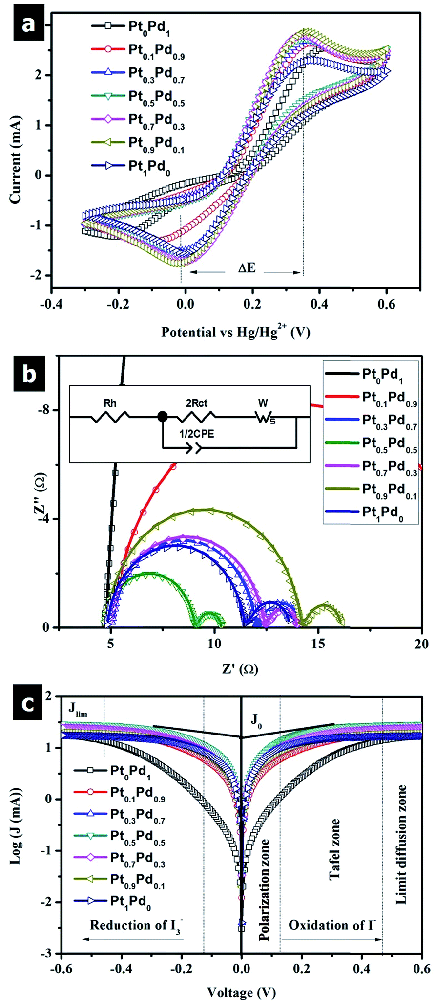 | ||
| Fig. 2 (a) Cyclic voltammograms of the electrodes; (b) Nyquist plots of symmetrical dummy cells with two identical CEs. The inset in (b) presents the equivalent circuit diagram used to fit the EIS spectra. (c) Tafel curves of different symmetrical dummy cells that are similar to those used for the EIS measurements. | ||
| Counter electrode | Pt1Pd0 | Pt0.9Pd0.1 | Pt0.7Pd0.3 | Pt0.5Pd0.5 | Pt0.3Pd0.7 | Pt0.1Pd0.9 | Pt0Pd1 | |
|---|---|---|---|---|---|---|---|---|
| a The data were calculated from the Tafel curve.b Jred: peak current density of reduction. ΔE: peak-to-peak separation. | ||||||||
| Jred | (mA) | −1.53 | −1.55 | −1.66 | −1.77 | −1.53 | −1.40 | −1.22 |
| ΔE | (mV) | 380 | 330 | 360 | 350 | 380 | 500 | 630 |
| Area | (×106) | 150 | 122 | 181 | 319 | 183 | 63 | 88 |
| Charge | (mC) | −7.53 | −7.11 | −7.59 | −9.64 | −7.63 | −3.14 | −0.9 |
| Rh | (Ω) | 4.88 | 4.74 | 4.64 | 4.64 | 5.13 | 5.2 | — |
| Rct | (Ω) | 4.17 | 4.7 | 4.28 | 2.19 | 3.8 | 9.43 | — |
| Zw | (Ω) | 2.26 | 1.98 | 1.64 | 1.29 | 2.36 | 2.23 | — |
| J0 | (mA) | 30.78 | 27.34 | 29.99 | 58.62 | 33.83 | 13.61 | — |
| J0a | (mA) | 3.4 | 23.4 | 43.0 | 58.8 | 41.4 | 37.2 | 43.4 |
| CPE-T | 8.93 | 6.72 | 8.42 | 9.97 | 6.82 | 6.8 | — | |
| Jsc | (mA cm−2) | 14.85 | 14.97 | 15.07 | 15.41 | 14.64 | 14.12 | 8.96 |
| Voc | (mV) | 755 | 750 | 735 | 735 | 750 | 740 | 695 |
| FF | (%) | 70.77 | 70.49 | 71.19 | 70.90 | 72.21 | 67.06 | 11.84 |
| η | (%) | 7.93 | 7.91 | 7.97 | 8.03 | 7.93 | 7.01 | 0.74 |
The peak-to-peak separation (ΔE) values, which were estimated from the CV curves, of all electrodes are also presented in Table 1. It should be noted that a decrease in ΔE indicates an increase in the redox reaction rate of I3−/I−.24 Thus, there is a correlation of the ΔE values from the CV curves with the Rct values estimated from the electrochemical impedance spectroscopy (EIS) measurements, and finally with the open-circuit voltage (Voc) levels in the DSCs.6,24
Fig. 2(b) presents the Nyquist plots of the symmetrical dummy cells fabricated with two identical electrodes. The parameters of the EIS spectra according to the equivalent circuits are fitted and summarized in Table 1. It was found that the trends of the internal resistance (Rh), Rct, and diffusion impedance (Zw) were similar to those of the Jred and total electric charge in the CV curves. The lowest values of Rh, Rct, and Zw were 4.64, 2.19, and 1.29 Ω, respectively, for the Pt0.5Pd0.5 electrode. These results are in good agreement with the CV analyses. It should be noted that a low Rh value indicates a low sheet resistance in the electrode, which indicates a high short-circuit current density (Jsc) in the DSCs.25 A low Rct value indicates the high catalytic activity of electrode toward the regeneration of the iodide ions from the triiodide ions. The obtained Rct results are consistent with those of the exchange current density (J0) through the expression J0 = RT/nFRct, where R is the gas constant, T is the temperature, n is the number of electrons involved in the reduction of the iodide electrolyte, and F is Faraday's constant, as well as the Tafel measurements in Fig. 2(c) and Table 1. It should be noted that a high J0 value indicates a high fill factor (FF) and a high Jsc in the DSC.23 Finally, a low Zw value indicates that the triiodide ions can be rapidly reduced to iodide ions under catalysis of the alloys in order to accelerate the diffusion of the triiodide ions.26 The obtained Zw values in the EIS agree with the limiting diffusion current density (Jlim) values, which were obtained from the Tafel measurements (Fig. 2(c)).
It is well known that the effect of the CEs on the efficiency of the DSCs is related to their electrical conductivity and electrochemical catalytic activity for the iodide/triiodide redox couple. Therefore, in order to correlate the properties of the developed CEs with the PV parameters of the devices used in these CEs, PV and IPCE (ESI, Fig. S11†) measurements of complete cells were conducted. Fig. 3(a) presents the J–V characteristics of the DSCs with different alloy CEs. The PV parameters are summarized in Table 1. It was found that the power conversion efficiency increased as the volume ratio of the Pt to Pd precursor decreased from 1:0 to 0.5:0.5, and it decreased as the volume ratio of Pt to Pd decreased from 0.5:0.5 to 0:1. The highest efficiency of 8.03% was achieved for the DSC fabricated with the Pt0.5Pd0.5 CE. The Jsc, Voc, and FF values were estimated to be 15.41 mA cm−2, 735 mV, and 70.90%, respectively. The highest electrochemical catalysis for the triiodide reduction is also depicted for the Pt0.5Pd0.5 CE. As noted before, the difference in the Voc values was supported by ΔE.6,24 It was found that the FF and Jsc values ranged from 11.84% to 72.21% and 8.96 to 15.41 mA cm−2, respectively. The low series resistance of a DSC, which primarily depends on the Rct value, can be used to explain the change in the FF.27 Furthermore, the high electrical conductivity of the electrodes, which depends on the Rh value, resulted in achieving high Jsc values. The results are in good agreement with the data reported elsewhere.25 The stability test of the cell using Pt0.5Pd0.5 CE shows no noticeable change in the Rh, but the Rct becomes better after aging during 14 days (ESI, Fig. S12†).
 | ||
| Fig. 3 (a) Characteristic J–V curves of DSCs with different CEs measured under standard conditions. (b) The relationship between the Pt volume percentage in the alloy CEs with the absolute efficiency increase Δη and the ratio of Δη to Pt volume precursor. | ||
In order to evaluate the effectiveness of the PtPd alloy CEs, the increase in the absolute efficiency (Δη) and the ratio of Δη to Pt volume percentage (Δη/v) were calculated for all CEs. The detailed calculations are provided in Table S3 (ESI†). The obtained results are plotted in Fig. 3(b). Note that the η of the device with the Pd(Pt0Pd1) CE was used as a reference point (0.74%). As seen in Fig. 3(b), the Δη increased rapidly with increases in the Pt volume percentage in the range of 10% to 50% and decreased slightly with further increases in the Pt volume percentage. The maximum Δη was found at a Pt volume percentage of 50%. Therefore, the observed dependence must result from the difference in the stoichiometry and structure of the alloy systems. This trend is also in good agreement with the trends of efficiency and electrochemical catalytic activity for various CEs. However, as seen in Fig. 3(b) and Table S2,† the difference in Δη for samples with a Pt volume percentage in the range of 30% to 90% was not prominent. Moreover, the Δη/v value decreased with increases in the Pt volume percentage. It was found that the highest Δη/v was achieved with a very small volume of Pt precursor (10%) used to synthesize the PtPd alloy. The result indicates the possibility of optimizing the Pt loading in the developed PtPd alloy CEs. Therefore, this study can be regarded as an effective strategy to minimize the use of Pt in PtPd alloy CEs, which indicates a decrease in the production cost of DSCs along with improvements in efficiency.
In summary, various PtPd alloys were successfully synthesized on FTO substrates using different volume ratios of Pd and Pt precursors via DPR under atmospheric pressure near room temperature. The size, shape, and distribution of the PtPd alloys on the FTO glass surface was controlled through changing the volume percentage of the Pd precursor in the mixed solution. The developed PtPd alloys were characterized using SEM and XPS, and finally tested as alternative CEs for DSCs. The electrochemical catalytic activity of the CEs was investigated with CV, EIS, and Tafel analyses. Furthermore, the electrochemical catalytic performance of the Pt0.5Pd0.5 alloy CE was found to be superior among the developed CEs. The DSC using the Pt0.5Pd0.5 alloy CE exhibited the highest performance of 8.03% compared with 7.93% for the DSC with a Pt CE and 0.74% for the device based on a Pd CE. The high electrochemical catalytic activity of the hybrid material along with the low Rct of 2.19 Ω contributed to the device efficiency. The optimum alloying of Pt and Pd using a very simple and scalable fabrication method such as DPR can be a very useful technology for the potential fabrication of PtPd alloy CEs in efficient DSCs.
Acknowledgements
This research was supported by a National Research Foundation (NRF) grant (2014R1A2A2A01006994), the Korea Research Fellowship Program (2015H1D3A1061830), and a Korea CCS R&D Center (KCRC) grant (2014M1A8A1049345). These are grants are funded by the Ministry of Science, ICT and Future Planning through the National Research Foundation of Korea.References
- B. O'Regan and M. Grätzel, Nature, 1991, 395, 583 Search PubMed.
- A. Hagfeldt, G. Boschloo, L. C. Sun, L. Kloo and H. Pettersson, Chem. Rev., 2010, 110, 6595 CrossRef CAS PubMed.
- N. Papageorgiou, W. F. Maier and M. Grätzel, J. Electrochem. Soc., 1997, 144, 876 CrossRef CAS.
- Q. Tang, H. Zhang, Y. Meng, B. He and L. Yu, Angew. Chem., Int. Ed., 2015, 54, 11448 CrossRef CAS PubMed.
- S. Thomas, T. G. Deepak, G. S. Anjusree, T. A. Arun, S. V. Nair and S. Nair, J. Mater. Chem. A, 2014, 2, 4474 CAS.
- V. D. Dao, S. H. Kim, H. S. Choi, J. H. Kim, H. O. Park and J. K. Lee, J. Phys. Chem. C, 2011, 115, 25529 CAS.
- H. Jeong, Y. Pak, Y. Hwang, H. Song, K. H. Lee, H. C. Ko and G. Y. Jung, Small, 2012, 8, 3757 CrossRef CAS PubMed.
- V. D. Dao and H. S. Choi, ACS Appl. Mater. Interfaces, 2016, 8, 1004 CAS.
- Q. Tang, J. Duan, Y. Duan, B. He and L. Yu, Electrochim. Acta, 2015, 178, 886 CrossRef CAS.
- V. D. Dao, Y. Choi, K. Yong, L. Larina, O. Shevaleevskiy and H. S. Choi, J. Power Sources, 2015, 274, 831 CrossRef CAS.
- V. D. Dao, Y. Choi, K. Yong, L. Larina and H. S. Choi, Carbon, 2015, 84, 383 CrossRef CAS.
- S. W. Yoon, V. D. Dao, L. Larina, J. K. Lee and H. S. Choi, Carbon, 2016, 96, 229 CrossRef CAS.
- V. D. Dao, Q. C. Tran, S. H. Ko and H. S. Choi, J. Mater. Chem. A, 2013, 1, 4436 CAS.
- B. Qi, L. Di, W. Xu and X. Zhang, J. Mater. Chem. A, 2014, 2, 11885 CAS.
- B. Lim, M. J. Jiang, P. H. C. Camargo, E. C. Cho, J. Tao, X. M. Lu, Y. Zhu and Y. Xia, Science, 2009, 324, 1302 CrossRef CAS PubMed.
- S. J. Guo, S. J. Dong and E. K. Wang, ACS Nano, 2010, 4, 547 CrossRef CAS PubMed.
- S. Du, Y. Lu and R. Steinberger-Wilckens, Carbon, 2014, 79, 346 CrossRef CAS.
- Y. Tang, X. Pan, C. Zhang, S. Dai, F. Kong, L. Hu and Y. Sui, J. Phys. Chem. C, 2010, 114, 4160 CAS.
- S. Mukherjee, B. Ramalingam, L. Griggs, S. Hamm, G. A. Baker, P. Fraundorf, S. Sengupta and S. Gangopadhyay, Nanotechnology, 2012, 23, 485405 CrossRef PubMed.
- Y. Hou, D. Wang, X. H. Yang, W. Q. Wang, B. Zhang, H. F. Wang, G. Z. Lu, P. Hu, H. J. Zhao and H. G. Yang, Nat. Commun., 2013, 4, 1583 CrossRef PubMed.
- T. L. Hsieh, H. W. Chen, C. W. Kung, C. C. Wang, R. Vittal and K. C. Ho, J. Mater. Chem., 2012, 22, 5550 RSC.
- L. I. Daikhin, A. A. Kornyshev and M. Urbakh, Electrochim. Acta, 1997, 42, 2853 CrossRef CAS.
- S. S. Jeon, C. Kim, J. Ko and S. S. Im, J. Phys. Chem. C, 2011, 115, 22035 CAS.
- S. Y. Jang, Y. G. Kim, D. Y. Kim, H. G. Kim and S. M. Jo, ACS Appl. Mater. Interfaces, 2012, 4, 3500 CAS.
- V. D. Dao, H. S. Choi and K. D. Jung, Mater. Lett., 2013, 92, 11 CrossRef CAS.
- G. R. Li, F. Wang, Q. W. Jiang, X. P. Gao and P. W. Shen, Angew. Chem., 2010, 122, 3735 CrossRef.
- L. Han, N. Koide, Y. Chiba, A. Islam, R. Komiya, N. Fuke, A. Fukui and R. Yamanaka, Appl. Phys. Lett., 2005, 86, 213501 CrossRef.
Footnotes |
| † Electronic supplementary information (ESI) available. See DOI: 10.1039/c6ra06940a |
| ‡ Woo-Yeol Lee and Van-Duong Dao contributed equally to this work. |
| This journal is © The Royal Society of Chemistry 2016 |