DOI:
10.1039/C6RA06546E
(Paper)
RSC Adv., 2016,
6, 56571-56579
Copper-based dye-sensitized solar cells with quasi-solid nano cellulose composite electrolytes†
Received
11th March 2016
, Accepted 7th June 2016
First published on 13th June 2016
Abstract
The study presented describes the preparation of solvent-free nano composite gel electrolytes in combination with copper(I)-based dye-sensitized solar cells (DSSCs). The electrolytes comprise poly(ethylene oxide) (PEO) and cellulose nano crystals (CNCs) and an I3−/I− redox shuttle. The quasi-solid-state DSSCs show increased photoconversion performance with increased amount of CNC in the electrolyte. DSSC performances measured on the day that the devices are fabricated show that when the electrolyte is composed of 80% CNC, a cell efficiency of 1.09% is reached compared to 1.16% using a standard liquid I3−/I− electrolyte. DSSCs containing the nano composites and the copper(I)-based dye show robust stability over time, and after 60 days, DSSCs with the PEO/CNC/I3−/I− electrolyte outperform those containing the liquid electrolyte.
Introduction
In order to meet future global energy demands in a sustainable manner, it is crucial to optimize methods of solar energy harvesting and conversion to electrical energy.1 The total energy reaching the Earth from the Sun in one hour is sufficient to fulfil the energy needs of mankind for one year.2 Since O'Regan and Grätzel first described the dye-sensitized solar cell (DSSC) with its revolutionary use of nanoparticulate TiO2 semiconductor to increase the active surface area of the photoanode,3 there has been an exponential growth in reports of DSSC research and in ever increasing device enhancements.4 Photoconversion efficiencies now reach 14.3%,5 demonstrating the feasibility of DSSCs as a competitive player in the solar energy conversion field. One important benefit of DSSCs is the advantageous cost of fabrication compared to conventional silicon-based solar cells.6,7
In an n-type DSSC, the most commonly employed semiconductor is TiO2 which absorbs UV light. Extension of the light-harvesting capacity of the device is achieved by adsorbing a coloured sensitizer onto the TiO2 surface, and this is usually a metal complex or a metal-free organic dye. Ruthenium(II) complexes continue to dominate among metal-based dyes, but with sustainability being a prevalent issue, copper(I)-containing sensitizers are now being intensively investigated.8–10 One of the advantages of utilizing copper is its abundance on Earth and its low cost (USD 4.6 per kg compared to the price of ruthenium, USD 1350.3 per kg as of February 2016 (ref. 11 and 12)). Copper(I) complexes used as sensitizers typically contain an {Cu(bpy)2} or {Cu(phen)2} core (bpy = 2,2′-bipyridine, phen = 1,10-phenanthroline) and exhibit metal-to-ligand charge transfer (MLCT) bands between 400 and 550 nm, an absorption range similar to that of the MLCT bands of ruthenium(II) sensitizers. However, the extinction coefficients for the first are about one-third of the second.8
A vulnerable part of a DSSC is the electrolyte, which typically contains an organic solvent. Due to evaporation or leakage, the volume of electrolyte in the device may reduce over time, ultimately resulting in a drop of the cell performance.7,13–15 This problem can, in part, be addressed by using organic solvents of low volatility (e.g. 3-methoxypropionitrile in place of MeCN), and there is also active interest in replacing the organic solvent by water.16 Another approach that has significant appeal is to substitute the liquid electrolyte by a solid or quasi-solid polymer electrolyte.17–20 The ion conducting properties of poly(ethylene oxide), (PEO), make it suitable for this purpose and it is already applied in a range of batteries, fuel cells and solar cells.21–23 To maintain the ion conductivity of PEO, regions of crystallinity must be suppressed in favour of amorphous elastomer segments. It is here that ion transport occurs due to enhanced segmental motion of the polymer chains.24,25 Reducing the crystalline fractions can be achieved through, for example, lightly crosslinking the polymer or adding nanofillers.26–28 The amount of crosslinking has a large impact on the segmental chain motion and, consequently, on the ion conducting properties of the material; too high a crosslinking density results in restricted ion transport. Therefore, a combination of moderate crosslinking and addition of nanoparticles is an interesting route to pursue. One class of nanoparticles of interest as a renewable additive is cellulose nanocrystals (CNC). These are derived from cellulose, the most abundant biopolymer on Earth. Cellulose is a linear polysaccharide (Scheme 1) mostly found in wood and plants cell walls. Its polymer chains are arranged in cellulose nanofibrills (CNF), which further assemble into cellulose fibres.29 CNFs contain both crystalline and amorphous regions. Treatment of cellulose fibres with a strong mineral acid hydrolyzes the amorphous regions while the crystalline parts remain more or less intact. The cellulose nanocrystals (CNC) are thereby liberated and may be isolated.29,30 The size of these nanoparticles depends on the cellulose source and the hydrolysis conditions (i.e. time, acid concentration and temperature). CNCs obtained from wood and cotton are typically 3–70 nm in width and 100–300 nm long.29
 |
| | Scheme 1 The structural repeat unit in cellulose. | |
CNCs have attracted a great deal of attention in recent decades as a result of their unique mechanical and thermal properties, and their wide-ranging applicability. They exhibit a low thermal expansion, low density, high aspect ratio, chiral nematic behaviour, large specific surface area, and high elastic modulus up to 140 GPa.29 CNCs are mainly exploited in nanocomposites in order to improve the mechanical performance of the host polymer matrix. However, CNCs have also been investigated for other applications including biomedical devices, membranes, optical nanomaterials and bio-based batteries.29,30 Earlier work by Chiappone et al. has shown that nanoscale microfibrillated cellulose exhibits a number of advantageous features when used as a filler in quasi-solid electrolytes for ruthenium-sensitized quasi-solid-state DSSCs.31 In addition, Bein et al. have employed CNCs as a template for the preparation of mesoporous titania for DSSCs.32 However, to the best of our knowledge, DSSCs employing CNC-based electrolytes have not previously been investigated. Its compatibility with PEO makes CNC an ideal candidate as a nanofiller in PEO polymer electrolytes.
In contrast to thermally induced polymerization, polymerization initiated by UV irradiation is rapid and facilitates polymerization at moderate temperatures. Hence, we have selected UV-initiated polymerization for the present work, it being the most convenient technique for use on a large scale.33 However, there are limitations on the quantity of nanofiller that can be included in a system designed to be polymerized through irradiation. Our current investigation also addresses this problem and the consequences regarding the DSSC performance when the CNC loading exceeds the maximum amounts appropriate for photo-polymerization.
Experimental
Materials
All reagents and solvents were purchased and used as received from Sigma-Aldrich without further purification unless otherwise specified. The homoleptic complex [Cu(Lancillary)2][PF6] and the anchoring ligand were prepared as described elsewhere34,35 and the dye (Scheme 2) was assembled in situ (see below). Tetraethylene glycol dimethacrylate (PEODMA, M = 330 g mol−1, Scheme 3a) and methoxy polyethylene glycol monomethacrylate (PEOMA, M = 494 g mol−1, Scheme 3b) were kindly supplied by Sartomer Company, Europe. The photoinitiator 2,2-dimethoxy-2-phenylacetophenone (DMPA) was purchased from Acros organics. Working TiO2 (∼12 μm TiO2 thickness) and counter Pt coated electrodes, cell sealing gaskets, and sealing foil were all purchased as test cell kits from Solaronix, Switzerland. The electrolyte solution for swelling of the nano composites was NaI (1.35 g, 9 mmol), I2 (0.28 g, 1.12 mmol) and 4-tert-butylpyridine, (TBP) 96%, (1.49 g, 11 mmol), diluted up to 20 mL with MeCN 99.8% (VWR). Solvents used for washing electrodes were MeCN (as above), ethanol (EtOH) ≥99.8%, dimethyl sulfoxide (DMSO) 99.8% (Acros organics). The CNCs used were prepared according to the procedure described by Weder et al.36 then dialyzed against deionized water for seven days. Subsequently, the CNCs were dispersed by ultrasonication employing the amplitude of 28% using pulse function (5 s pulse on and 2 s pulse off) for 30 minutes, and filtered on glass filter pore 1 to remove any large particles. The resulting water suspension had a CNC concentration of 1.4 wt%.
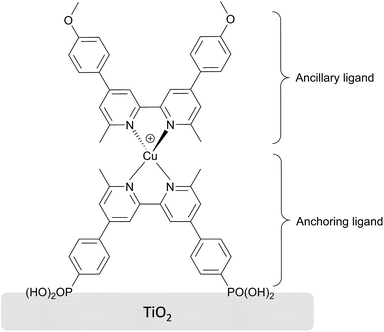 |
| | Scheme 2 Structure of the copper based dye sensitizer used in the study. | |
 |
| | Scheme 3 Structures of the PEO oligomers used in the study; (a) PEODMA and (b) PEOMA. | |
Techniques and procedures
Preparation of the nano composite electrolytes. Oligomer solution was prepared with a 6![[thin space (1/6-em)]](https://www.rsc.org/images/entities/char_2009.gif) :94 (PEODMA:PEOMA, wt%) ratio, followed by DMPA (2 wt% of oligomers), which was shaken until it completely dissolved. The CNC water suspension was added to a set of vials, followed with oligomer solution in appropriate amounts to obtain the CNC concentrations desired in each vial. The samples were then placed in an oven at 70 °C overnight, followed by UV irradiation for 30 minutes. After polymerization, liquid I3−/I− electrolyte solution was added to each sample, which was allowed to swell for 1 hour. Finally, each sample was dried under high vacuum to remove all acetonitrile.
:94 (PEODMA:PEOMA, wt%) ratio, followed by DMPA (2 wt% of oligomers), which was shaken until it completely dissolved. The CNC water suspension was added to a set of vials, followed with oligomer solution in appropriate amounts to obtain the CNC concentrations desired in each vial. The samples were then placed in an oven at 70 °C overnight, followed by UV irradiation for 30 minutes. After polymerization, liquid I3−/I− electrolyte solution was added to each sample, which was allowed to swell for 1 hour. Finally, each sample was dried under high vacuum to remove all acetonitrile.
Immobilization of ligands on TiO2 electrodes and preparation of DSSCs. TiO2 electrodes were carefully washed with EtOH and subsequently heated up to 455 °C for 20 minutes. After cooling to ca. 80 °C, the electrodes were immersed in the phosphonic acid anchoring ligand (Scheme 2 bottom) solution (0.1 mM in DMSO) for 24 hours. The anchoring ligand-immobilized electrodes were then carefully washed with DMSO, followed by MeCN and submerged in an MeCN solution (0.1 mM) of [Cu(Lancillary)2][PF6] (see top of Scheme 2 for Lancillary) where it was left for three days. After this time, the dye-sensitized electrodes were taken out of the solution, rinsed thoroughly with MeCN and dried under an N2 stream. Then, 5 mg of the electrolyte paste was smeared onto the electrodes. Pt coated cathode electrodes which had been cleaned the same way as the anodes, were sealed together with the anode using a hot melt sealing foil with an initial thickness of 60 μm.
Thermogravimetric analysis, (TGA). TGA measurements were carried out on a Mettler Toledo TGA/SDTA851e under nitrogen. The temperature was increased from room temperature to 600 °C with a heating rate of 10 °C min−1, and the data were recorded from 35 °C.
Fourier-transform infrared spectroscopy, (FT-IR). FT-IR measurements were carried out on the samples after polymerization and electrolyte swelling/vacuum drying in the range 4000 to 400 cm−1 on a Perkin-Elmer Spectrum TWO LiTa instrument, equipped with a UATR diamond crystal. Each spectrum was based on 12 scans. The penetration depth was around 1–5 μm depending on the wavenumber. All the IR measurements were carried out in reflection mode, with a resolution of 4 cm−1.
J–V measurements. J–V measurements were made by irradiating the DSSC using a light source LOT Quantum Design LS0811 (100 mW cm−2 = 1 sun). A reference Si cell was used to calibrate the power of the simulated light. All DSCs were masked37,38 before measurements were made.
Electrochemical impedance spectroscopy (EIS). EIS measurements were carried out on a ModuLab® XM PhotoEchem photoelectrochemical measurement system setup from Solartron Analytical. The impedance was measured at steady state close to the open-circuit potential of the cell at different light intensities (LED, 650 nm) in the frequency range 0.05 Hz to 400 kHz using an amplitude of 10 mV. The impedance data was fitted to an equivalent circuit model and analyzed using ZView® software from Scribner Associates Inc.
Results and discussion
Polymerization of nano composites
General properties. The present study includes PEO/CNC nano composites with a wide distribution of CNC content, ranging from 0 to 100%. In Table 1, the CNC amount for each sample together with some material properties are shown. After the polymerization step, the samples CNC0 through CNC80 show some varying physical properties; samples CNC0 to CNC40 are smooth and non-sticky. As the CNC content reaches 60%, stickiness occurs and when more CNC is added (i.e. 80%) the sample is pasty.
Table 1 Some key values of the nano compositesa
| Sample name |
Wt% CNC |
α |
T2% [°C] |
T5% [°C] |
| T2% and T5% are the values on the temperature at which the weight loss of the samples are 2 and 5% respectively. |
| Ref. (L) |
n/a (liquid) |
n/a |
n/a |
n/a |
| CNC0 |
0% |
100 |
236 |
265 |
| CNC5 |
5% |
100 |
242 |
272 |
| CNC10 |
10% |
100 |
243 |
272 |
| CNC20 |
20% |
99 |
246 |
266 |
| CNC40 |
40% |
98 |
240 |
263 |
| CNC60 |
60% |
89 |
218 |
239 |
| CNC80 |
80% |
84 |
221 |
241 |
| CNC100 |
100% |
n/a |
285 |
309 |
| Oligomers |
n/a |
n/a |
177 |
199 |
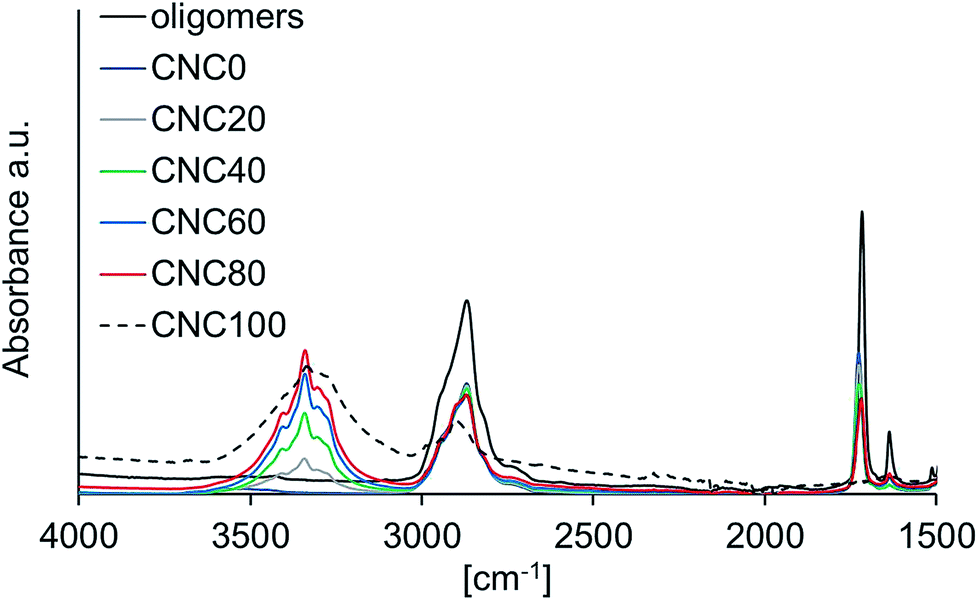
FT-IR characterization. From the FT-IR spectra (Fig. 1), it can be seen that as the amount of CNC is increased, (especially from 20 to 40%) the broad absorption at ∼3300 cm−1 increases in intensity, indicating a significant increase in the number of hydroxyl groups.
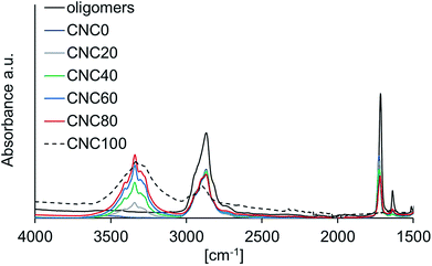 |
| | Fig. 1 FT-IR spectra of all nano composite samples after UV irradiation as well as the unpolymerized oligomer solution. Spectra of samples CNC5 and CNC10 are omitted for clarity. | |
FT-IR spectroscopy was also used to investigate the degree of polymerization of the nano composites. The variance of the amount of unreacted methacrylate groups as more CNC is added can be seen in Fig. 2 which shows the FT-IR spectra for the samples with different content of CNC, focusing on the carbonyl- and acrylate absorptions at ∼1727 cm−1 and 1637 cm−1, respectively. The more CNC present, the less the conversion of methacrylate groups occurs due to UV irradiation shielding effects as more filler is added to the system. The intensity of the peak corresponding to the methacrylate vinyl bond stretch (1637 cm−1) can be used to approximatively determine the degree of polymerization, α, (Table 1, Fig. 2) with the size of the carbonyl peak used as an internal reference, and the methacrylate group peak for CNC0 used as standard for the fully polymerized sample. It is observed that as the amount of CNC is increased, the degree of polymerization drops. As the CNC content exceeds 40%, the oligomer methacrylate group conversion decreases under 90%. This will result in an overall lower segmental molecular weight, and in turn increases the ability for the electrolyte to penetrate the porous dye-sensitized TiO2 layer. A better polymer electrolyte penetration of the sensitized semiconductor enhances the contact between electrolyte and dye, thus increasing the electron transport abilities. However, this might very well be affected over time, as more oligomer might react or molecular rearrangement may occur.
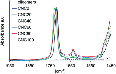 |
| | Fig. 2 Expansion of the carbonyl region of the FT-IR spectra of the samples after polymerization, where the influence on the degree of polymerization as a function of CNC content can be seen from the magnitude of the methacrylate vinyl bond stretch peak at 1637 cm−1. All spectra are normalized with respect to the carbonyl peak of sample CNC0. Spectra of samples CNC5 and CNC10 are omitted for clarity. | |
Electrolyte swelling and post-drying. As the samples are soaked in electrolyte solution and dried through vacuum evaporation of the solvent, an increased amount of CNC enhances the ability of the composite to withstand the swelling of the material. Sample CNC0 shows a very small tolerance towards electrolyte swelling. It is, after drying, a grainy, crumbly gel with very low acceptance to physical stress. As discussed earlier, it is crucial to remove all acetonitrile in order to achieve long-time stability of the cell. Fig. 3 shows an FT-IR spectrum of MeCN and sample CNC40 after evaporation of the MeCN. It is clear that the characteristic peak at 2200–2400 cm−1 arising from the C![[triple bond, length as m-dash]](https://www.rsc.org/images/entities/char_e002.gif) N stretching mode of the acetonitrile disappears after drying.
N stretching mode of the acetonitrile disappears after drying.
 |
| | Fig. 3 FT-IR spectrum of acetonitrile (![[thick line, graph caption]](https://www.rsc.org/images/entities/char_e117.gif) ) and sample CNC40 after vacuum drying ( ) and sample CNC40 after vacuum drying (![[dash dash, graph caption]](https://www.rsc.org/images/entities/char_e091.gif) ). ). | |
Thermal stability and water content. TGA was used to assess the thermal stability of the composites and confirm the absence of water since this can be difficult to deduce from FT-IR spectra. The TGA thermograms in Fig. 4a confirms that very limited amounts of water are present in the nano composites, and that they are all thermally stable up to 210 °C. Fig. 4b shows that on going from 0 to 10% CNC content, a slight increase in T2% and T5% occurs (Table 1). However, a more pronounced temperature drop is seen when further increasing the CNC content from 10 up to 80%, and is especially noticeable between CNC40 and CNC60. This is not an effect of increased water content due to increased amount of CNC, since CNC100 has the highest weight-loss temperatures. Rather, it is a consequence of a lower degree of polymerization, where a lower average molecular weight should lower the weight-loss temperature. This assumption also agrees with the slight increase of weight-loss temperature of the samples CNC0–CNC10, where CNC with a higher degradation temperature than PEO is pushing this value upwards as the amount of CNC is increased.
 |
| | Fig. 4 Results from TGA measurements on the samples after polymerization as well as of the unpolymerized oligomer solution (a) and T2% and T5% as function of CNC content (b). The black coloured data points in (b) represent T2% and T5% for the unpolymerized oligomer solution. | |
When the CNC exceeds 10%, the lower degree of polymerization starts to play a role. It is effectively illustrated in Fig. 4b, if studying T2% and T5% for the unpolymerized sample.
DSSC performances. The I3−/I− electrolyte/nano composite paste (see Experimental section) was combined in DSSCs with the copper(I) dye shown in Scheme 2. The most fundamental DSSC characterization is by J–V measurements to determine the photoconversion efficiency (η), the fill factor (FF), the open circuit potential (Voc) and the short circuit current density (Jsc) of the DSSCs. The results are given in Table 2, and Fig. 5 shows η as function of CNC content and aging time. The amount of CNC added has a dramatic effect on η. The efficiency increases ∼19-fold when going from the neat PEO sample to the sample containing 80% CNC, and this is the best performing nano composite device in the study.
Table 2 Some key values of the performance of the DSSCsa,b
| Sample name |
η [%] |
Jsc [mA cm−2] |
Voc [mV] |
FF [%] |
| Values presented are average results from duplicate cells; the individual values are given in ESI Table S1. Values presented in this table is from measurements carried out on the same day as the DSSCs were made. For trends over longer time periods, please refer to results presented in Fig. 5. |
| Ref. (L) |
1.16 |
3.1 |
540 |
70 |
| CNC0 |
0.08 |
0.3 |
625 |
48 |
| CNC5 |
0.26 |
1.9 |
485 |
27 |
| CNC10 |
0.39 |
2.5 |
509 |
30 |
| CNC20 |
0.54 |
2.6 |
526 |
39 |
| CNC40 |
0.89 |
2.3 |
571 |
67 |
| CNC60 |
0.96 |
2.8 |
569 |
60 |
| CNC80 |
1.09 |
2.8 |
583 |
66 |
| CNC100 |
0.61 |
2.0 |
602 |
50 |
 |
| | Fig. 5 DSSC efficiency, η, as a function of CNC content and aging time. The results depicted are average values of duplicate cells. | |
One of the most central parameters of this study is the stability of the DSSC over time, where the nano composite samples show outstanding durability with respect to a reference DSSC containing liquid electrolyte, as well as compatibility with copper-based dyes. After 60 days, the DSSC with liquid electrolyte operates at only 48% of its initial efficiency (Fig. 5, left, Ref. (L)). In contrast, the DSSC containing 80% CNC is significantly more stable with a photoconversion efficiency after 60 days that is 79% of the initial value (Fig. 5, right). The cell containing 60% CNC shows the best stability over time, maintaining ∼85% of its initial η after 60 days.
Although the samples CNC60–CNC80 appear from Fig. 5 to be the most promising, as stated above, if the CNC content in the nano composites exceeds 40%, the degree of polymerization is no longer adequate. Therefore, it is more appropriate to compare the efficiency data of CNC40, which has a degree of polymerization ≥ 90%, with that of the liquid reference cell. This comparison reveals a 27% difference between the values of η with absolute cell efficiency for the composite DSSC 0.1% higher than the liquid cell after 60 days of aging. When the cells were first assembled, the absolute efficiency of the liquid reference cell exceeded that of CNC40 by 0.27%. These results, as well as an assessment of previous studies,7,13–15,31 emphasize the detrimental effects of solvent evaporation and leakage occurring in liquid electrolyte DSSCs. The samples having no PEO at all (i.e. CNC100) malfunction even after one week, and this is rationalized by poor interfacial contact and the lack of an appropriate ion transport phase. The interfacial contact issues will be discussed further on in the electrochemical impedance spectroscopic part of this paper.
Fig. 6 and 7 show the values of Voc and Jsc, respectively, of the devices on the day the DSSCs were assembled, and after the cells have been aged for 14 and 60 days. Across the series of DSSCs containing CNC5 to CNC100, Voc and Jsc generally increase as the CNC content increases. It has been shown by Chiappone et al.31 that light scattering properties of the crystalline segments in cellulose nanofibres will direct some of the lost photons back into the active layer and this would explain the trends observed here. The largest change in Voc over the 2 week period is found for the liquid reference cell and that containing composite CNC0; the latter DSSC possesses the highest Voc and also the lowest Jsc. The high Voc can be explained by the fact that the anode is in insufficient contact with the electrolyte, thus restricting recombination reactions. As the CNC content is increased, the contact is enhanced and the value of Voc becomes closer to the ones of the reference DSC with liquid-electrolyte, Ref. (L). Voc eventually increases again as the CNC content reaches 80% as the interfacial contact is again restricted. A consequence of inadequate electrolyte/cathode contact is that less I3− will be available for reduction to I− at the counter electrode which in turn will lead to lower current density which is described by the Butler–Volmer's eqn (1).
| |
 | (1) |
where
cred and
cox represent I
− and I
3− concentrations,
k0 is the electron transfer constant at no overpotential,
α is a symmetry factor normally close to 0.5 and
η is the activation overpotential.
 |
| | Fig. 6 Values of Voc as a function of CNC composition at different aging times. | |
 |
| | Fig. 7 Values of Jsc as a function of CNC composition at different aging times. | |
Jsc is essentially dependent on the ability of the DSSC to convert photons into electric current. An important parameter in this respect is the ionic conductivity of the electrolyte and, hence, the contact at the electrode/electrolyte interface. Therefore, it is not surprising that Jsc of the DSSC containing CNC0 is as low as <0.2 mA cm−2.
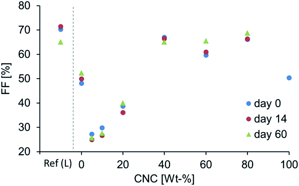
A comparison of the J–V curves in Fig. 8 reveals that the DSSC containing CNC40 is the first DSSC (i.e. as the proportion of CNC is increased) that exhibits a curve profile consistent with that of a liquid cell with a significant increase in the FF (Table 2). The device with composite CNC40 has a relatively high Voc but a slightly lower Jsc than expected from the general trend (Fig. 6 and 7). However, the FF is rather high due to its higher Pmax, which follows from an increased electrolyte/electrode contact as the CNC composition increases (Fig. 9).
 |
| | Fig. 8 J–V curves from one of the duplicate series of DSSCs at 0 days of aging. | |
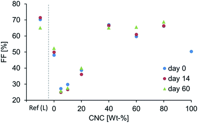 |
| | Fig. 9 Values of FF as function of CNC composition at different aging times. | |
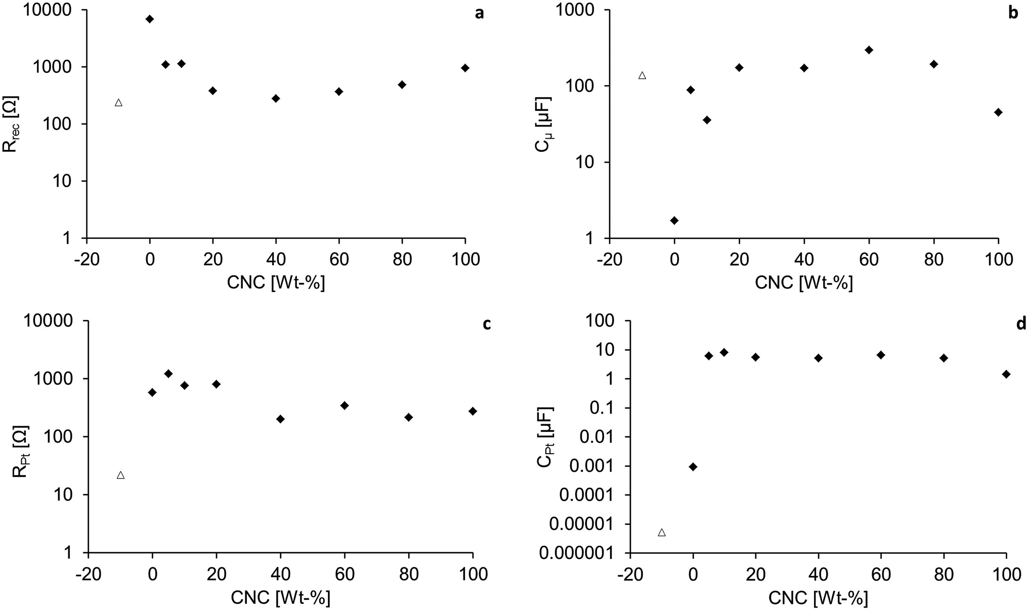
Impedance characteristics. In order to assess the internal impedances of the cells, electrochemical impedance spectroscopy (EIS) was performed. EIS is a powerful diagnostic tool to determine parameters including the recombination resistance (Rrec), active layer capacitance (Cμ), charge transfer resistance and capacitance at the cathode (RPt and CPt respectively).39–42 The DSSC is subjected to an AC current frequency sweep at steady state close to Voc, and the impedance at any given frequency is recorded. In a Nyquist plot, the impedances are presented as semi-circles. As a consequence of the frequency used to generate each impedance response, the semi-circles will be distributed in the plot at various positions, corresponding to different processes in the cell. In the Nyquist plot, the actual value of the frequency at each measuring point is not displayed. However, the high frequency (HF) region is to the left and the medium- to low frequency (MF, LF) regions are in the middle and to the right respectively. For EIS measurements designed for DSSCs, the cell is normally under bias light of different intensities to reveal more information about the behaviour of the internal processes of the cell. Fig. 10 shows a Nyquist plot for the DSSC containing CNC40 at different bias light intensities. It is crucial to correctly assign each semi-circle to a certain process within the cell and varying the light intensities is an appropriate way to do this. In Fig. 10 it can be seen that as the light intensity is lowered, the LF semi-circle increases in size, while the HF semi-circle is less affected. Since the recombination should decrease at lower voltages, it is reasonable to assume that this circle describes the recombination resistance. The cathode, which is not photo active, should remain fairly constant at any bias light intensity, which is the case of the circle to the left.
 |
| | Fig. 10 The Nyquist plot of sample CNC40 at a few different bias light intensities. The enlarged marker in each series is the data point measured at 2.5 Hz. | |
The recombination resistance with respect to the dye should be similar in all samples. However, from Fig. 11a it is clear that this is not the case. The reference liquid electrolyte cell has an Rrec of around 200 Ω. When the DSSC contains electrolyte CNC0, Rrec dramatically increases. As the CNC content is further increased, Rrec becomes smaller until a 40% CNC composition is reached, after which more CNC gives rise to an increase in Rrec. It is interesting to note that CNC40 has Rrec and Cμ values close to the ones of the liquid reference cell. However, this is not the case with RPt and CPt of the back electrode, indicating that the cathode/electrolyte contact is the main factor preventing CNC40 from performing as well as the liquid DSSC, at least before the device has aged. For DSSCs containing CNC60, Cμ is higher (Fig. 11b), as are Jsc, Voc and η, but this is also expected due to the decreased degree of polymerization, which gives rise to better interfacial contact. At zero or a low amount of CNC, the nano composites are very brittle and flaky after electrolyte swelling. This would explain the rather high Rrec; as mentioned above, the low Jsc is due to poor electrolyte/electrode contact. It also explains the high Voc of CNC0 (see Discussion above). As the CNC content is increased, the composite can withstand the impact of the electrolyte swelling, and is more compliant when placed in the cell. As a result, Rrec decreases and the capacitance of the active layer, Cμ, increases. As a consequence, the back reactions escalate as well and the value of Voc decreases and attains values close to the ones of the reference liquid cell. When a large amount of CNC is present as in CNC80–CNC100, Rrec increases again and Cμ drops, accompanied by increasing Voc.
 |
| | Fig. 11 Results from EIS measurements; (a) Rrec, (b) Cμ, (c) RPt and (d) CPt. The triangular shaped (Δ) marker represents the values for Ref. (L). The fitted curves are given in the ESI Table S2.† | |
The fact that the capacitance drops although the Rrec increases shows that a reduced quantity of charge resides on the TiO2 upon irradiation, thus emphasizing the contact difficulties when a large amount of CNC is added. This also is consistent with the slightly higher Voc, lower Jsc and FF shown in Fig. 6, 7 and 9.
As discussed above, the DSSC containing CNC40 has a slightly lower Jsc than expected in the series, but a higher Pmax and subsequently, a higher FF. In Fig. 11c, the cathode/electrolyte charge transfer resistance, RPt, dramatically decreases as a consequence of improved charge transfer contact which is, in turn, related to the lower degree of polymerization. Indeed, from an interface contact point of view (Fig. 11), DSSCs containing CNC20–CNC60 should have around the same efficiency. However, Fig. 5 shows that this is not the case, and we suggest that the increased scattering effects is the factor leading to improved η values. Fig. 11d depicts the counter electrode capacitance, CPt. The liquid reference cell shows a moderate accumulation of charge in the interfacial layer, meaning that the charge transfer here is instant. CNC0 has, due to its physical properties mentioned above, a very poor contact with the Pt electrode which results in scarcity of I3− available for reduction to I−. A lower capacitance is, in accordance with the discussion in device performance section, a consequence. At higher amounts of CNC, CPt is rather constant, but falls when 100% CNC is present. This implies that for DSSCs with CNC5–CNC80, it is the general charge transfer impedance of having a polymer instead of a liquid that gives rise to the higher capacitance. Compared to the DSSC with CNC0, the counter electrode/electrolyte contact is improved which is also reflected in the η values of the series.
Conclusions
A series of DSSCs sensitized with the bis(diimine)copper(I) dye shown in Scheme 2 and with a nano cellulose composite incorporated into the I3−/I−-based electrolyte has successfully been fabricated. The amount of CNC added has a large impact on the performances of the cells, with a larger amount leading to a significant improvement in photoconversion efficiency. However, when the CNC content exceeds 40%, the degree of polymerization is, as seen in FT-IR measurements, not sufficient. The risk of cell performance drop over time as a consequence of cell leakage is highest when the composite electrolyte is not adequately polymerized. Hence, it is important to monitor the success of polymerization to maintain a high performance of the DSSC over time. We have shown that the nano composite electrolytes are compatible with copper(I)-based DSSCs, and the stability of all nano composite DSSCs has proven to be superior to the liquid reference cell when the cells are aged. The results highlight the importance of good interfacial contact between the quasi-solid electrolyte and the electrodes. It was shown through EIS characterization that the addition of CNC to the PEO matrix decreases the charge transfer resistance of these interfaces, especially at the photoanode. The sample with as much as 40% CNC content (sample CNC40) is polymerized to a sufficient degree. This DSSC shows Rrec and Cμ values similar to those of the liquid reference DSSC, but has a higher stability. The photoconversion efficiency of this cell exceeds the value of the liquid cell after 60 days. Overall, these results show that PEO/CNC nano composites can be swiftly manufactured and used with bis(diimine)copper(I) sensitized electrodes to form DSSCs having electrolytes of cheap, stable and, largely, renewable resources.
Acknowledgements
We acknowledge the Swiss National Science Foundation (Grant number 200020_162631), the European Research Council (Advanced Grant 267816 LiLo), the Swiss Nano Institute (for the purchase of the EIS instrument) and the University of Basel for financial support. Dr Sebastian Fürer is acknowledged for helpful discussions. Cedric Wobill and Annika Büttner are acknowledged for providing the ancillary and anchoring ligands, respectively.
Notes and references
- P. V. Kamat, J. Phys. Chem. C, 2007, 111, 2834–2860 CAS.
- O. Morton, Nature, 2006, 443, 19–22 CrossRef CAS PubMed.
- B. O'Regan and M. Grätzel, Nature, 1991, 353, 737–740 CrossRef.
- A. Hagfeldt, G. Boschloo, L. Sun, L. Kloo and H. Pettersson, Chem. Rev., 2010, 110, 6595–6663 CrossRef CAS PubMed.
- K. Kakiage, Y. Aoyama, T. Yano, K. Oya, J.-I. Fujisawa and M. Hanaya, Chem. Commun., 2015, 51, 15894–15897 RSC.
- M. Grätzel, J. Photochem. Photobiol., C, 2003, 4, 145–153 CrossRef.
- P. Wang, S. M. Zakeeruddin, J. E. Moser, M. K. Nazeeruddin, T. Sekiguchi and M. Grätzel, Nat. Mater., 2003, 2, 402–407 CrossRef CAS PubMed.
- C. E. Housecroft and E. C. Constable, Chem. Soc. Rev., 2015, 44, 8386–8398 RSC.
- Y. M. Klein, M. Willgert, A. Prescimone, E. C. Constable and C. E. Housecroft, Dalton Trans., 2016, 45, 4659–4672 RSC.
- A. Büttner, S. Y. Brauchli, R. Vogt, E. C. Constable and C. E. Housecroft, RSC Adv., 2016, 6, 5205–5213 RSC.
- http://www.lme.com/metals/non-ferrous/copper/, accessed February 22 2016.
- https://www.quandl.com/collections/markets/rare-metals, accessed February 22 2016.
- Y. Jiang, Y. L. Cao, P. Liu, J. F. Qian and H. X. Yang, Electrochim. Acta, 2010, 55, 6415–6419 CrossRef CAS.
- J. Kim, J. K. Koh, B. Kim, S. H. Ahn, H. Ahn, D. Y. Ryu, J. H. Kim and E. Kim, Adv. Funct. Mater., 2011, 21, 4633–4639 CrossRef CAS.
- A. Konno and E. V. A. Premalal, J. Photopolym. Sci. Technol., 2010, 23, 279–282 CrossRef CAS.
- F. Bella, C. Gerbaldi, C. Barolo and M. Gratzel, Chem. Soc. Rev., 2015, 44, 3431–3473 RSC.
- C.-L. Chen, T.-W. Chang, S.-C. Su, H. Teng and Y.-L. Lee, J. Power Sources, 2014, 247, 406–411 CrossRef CAS.
- R.-K. Zhang, Z. Sun, H.-H. Xie, X. Wu, M. Liang and S. Xue, Sol. Energy, 2012, 86, 2346–2353 CrossRef CAS.
- R.-X. Dong, S.-Y. Shen, H.-W. Chen, C.-C. Wang, P.-T. Shih, C.-T. Liu, R. Vittal, J.-J. Lin and K.-C. Ho, J. Mater. Chem. A, 2013, 1, 8471–8478 CAS.
- D. Song, W. Cho, J. H. Lee and Y. S. Kang, J. Phys. Chem. Lett., 2014, 5, 1249–1258 CrossRef CAS PubMed.
- J. M. Tarascon and M. Armand, Nature, 2001, 414, 359–367 CrossRef CAS PubMed.
- H. Y. Chang and C. W. Lin, J. Membr. Sci., 2003, 218, 295–306 CrossRef CAS.
- I. C. Flores, J. Nei de Freitas, C. Longo, M.-A. De Paoli, H. Winnischofer and A. F. Nogueira, J. Photochem. Photobiol., A, 2007, 189, 153–160 CrossRef CAS.
- C. Berthier, W. Gorecki, M. Minier, M. B. Armand, J. M. Chabagno and P. Rigaud, Solid State Ionics, 1983, 11, 91–95 CrossRef CAS.
- B. L. Papke, M. A. Ratner and D. F. Shriver, J. Electrochem. Soc., 1982, 129, 1694–1701 CrossRef CAS.
- J. R. MacCallum, M. J. Smith and C. A. Vincent, Solid State Ionics, 1984, 11, 307–312 CrossRef CAS.
- P. Meneghetti, S. Qutubuddin and A. Webber, Electrochim. Acta, 2004, 49, 4923–4931 CrossRef CAS.
- F. Croce, G. B. Appetecchi, L. Persi and B. Scrosati, Nature, 1998, 394, 456–458 CrossRef CAS.
- Y. Habibi, L. A. Lucia and O. J. Rojas, Chem. Rev., 2010, 110, 3479–3500 CrossRef CAS PubMed.
- N. Lin, J. Huang and A. Dufresne, Nanoscale, 2012, 4, 3274–3294 RSC.
- A. Chiappone, F. Bella, J. R. Nair, G. Meligrana, R. Bongiovanni and C. Gerbaldi, ChemElectroChem, 2014, 1, 1350–1358 CrossRef CAS.
- A. Ivanova, D. Fattakhova-Rohlfing, B. E. Kayaalp, J. Rathousky and T. Bein, J. Am. Chem. Soc., 2014, 136, 5930–5937 CrossRef CAS PubMed.
- C. Decker, Prog. Polym. Sci., 1996, 21, 593–650 CrossRef CAS.
- E. C. Constable, C. E. Housecroft, M. Neuburger, I. Poleschak and M. Zehnder, Polyhedron, 2003, 22, 93–108 CrossRef CAS.
- B. Bozic-Weber, S. Y. Brauchli, E. C. Constable, S. O. Fürer, C. E. Housecroft, F. J. Malzner, I. A. Wright and J. A. Zampese, Dalton Trans., 2013, 42, 12293–12308 RSC.
- O. van den Berg, M. Schroeter, J. R. Capadona and C. Weder, J. Mater. Chem., 2007, 17, 2746–2753 RSC.
- H. J. Snaith, Nat. Photonics, 2012, 6, 337–340 CrossRef CAS.
- H. J. Snaith, Energy Environ. Sci., 2012, 5, 6513–6520 Search PubMed.
- Q. Wang, S. Ito, M. Grätzel, F. Fabregat-Santiago, I. Mora-Sero, J. Bisquert, T. Bessho and H. Imai, J. Phys. Chem. B, 2006, 110, 25210–25221 CrossRef CAS PubMed.
- J. Bisquert, J. Phys. Chem. B, 2002, 106, 325–333 CrossRef CAS.
- Q. Wang, J.-E. Moser and M. Grätzel, J. Phys. Chem. B, 2005, 109, 14945–14953 CrossRef CAS PubMed.
- P. R. F. Barnes and B. C. O'Regan, J. Phys. Chem. C, 2010, 114, 19134–19140 CAS.
Footnote |
| † Electronic supplementary information (ESI) available: Table S1: DSC parameters; Table S2: Nyquist and Bode plots. See DOI: 10.1039/c6ra06546e |
|
| This journal is © The Royal Society of Chemistry 2016 |
Click here to see how this site uses Cookies. View our privacy policy here. 
 Open Access Article
 This Open Access Article is licensed under a