
Electrochemical behaviour of chromium–graphene composite coating
Rekha M. Y.,
M. K. Punith Kumar and
Chandan Srivastava*
Department of Materials Engineering, Indian Institute of Science, Bangalore, India. E-mail: csrivastava@materials.iisc.ernet.in; Tel: +91-80-22932834
First published on 22nd June 2016
Abstract
This work illustrates the role of graphene in enhancing the corrosion resistant properties of chromium–graphene composite coating when compared to the corrosion resistant properties of pure chromium coating containing ZnO nanoparticles. Chromium based coatings have been used extensively due to their various useful attributes such as corrosion and wear resistance and enhanced surface finish. In this work, Cr and Cr–graphene composite coatings were electrodeposited over mild steel substrate using Cr(III) plating bath. To deposit the coatings, an electrodeposition method was also adopted due to its attributes such as low cost, less equipment intensive methodology, accuracy of reproduction and suitability for large scale surface modification. Three different coatings were produced: (a) Cr coating containing ZnO nanoparticles (C), (b) Cr coating containing ZnO nanoparticles deposited using formic acid (CF) and (c) Cr coating containing ZnO nanoparticles and graphene deposited using formic acid (CFG). Graphene used in the deposition process was produced from the electrochemical exfoliation of graphite in sodium lauryl sulphate (SLS) electroactive media. ZnO nanoparticles were synthesized using the precipitation method followed by calcination. Microstructural characterization of the coatings revealed that the coating ‘C’ contained large cracks. Addition of formic acid (in the coating CF) noticeably reduced the cracks in the coating which now also contained hillock structures. Addition of graphene (in coating CFG) further enhanced the coating morphology which now contained negligible cracks and increased hillock structures completely covering its surface. Diffraction analysis revealed that the addition of graphene also altered the texture of the chromium coatings. Potentiodynamic polarization and electrochemical impedance spectroscopic analysis revealed that the change in the morphology and microstructure of the deposit due to the addition of graphene substantially enhanced the corrosion resistance of the CFG coating when compared to both C and CF coatings.
Introduction
Hard chromium coatings are extensively applied due to attributes such as mechanical strength,1 wear and corrosion resistance,2 and ability to provide decorative appearance to tools and machineries etc.3 Generally, a chromium plating bath containing Cr(VI)/hexavalent chromium ions is used to deposit chromium.4 Carcinogenicity and serious environmental problems posed by the hexavalent chromium ions has encouraged development of eco-friendly trivalent chromium/Cr(III) plating baths5 for depositing chromium coatings. It was however observed that the chromium coatings produced from trivalent chromium bath contained cracks which deteriorated the ability of the coating towards protecting the degradation of the underlying substrate.2,6 Cracks can be reduced by modifying the morphology of the deposit by altering the deposition parameters or using additives.7 Danilov et al.8 and Surviliene et al.9 produced crack free chromium coating using trivalent chromium plating bath with formic acid (HCOOH) as an additive.8,9 Addition of formic acid changes the morphology of the deposit making it crack free and enhancing its properties.8,9 In an another approach, incorporation of Al2O3 (ref. 10) and SiC11 nanoparticles into the chromium metal matrix also made the chromium deposit free from pores and micro-cracks. Juneghani et al.11 electrodeposited Cr–SiC composite coating and studied the effect of the SiC nanoparticles on wear and corrosion resistance property of the coatings.11 The incorporation of SiC nanoparticles into the chromium metal matrix improved the wear and corrosion resistance of the coating by making the deposit pore and crack free. Also, WC,12 Al2O3/SiC,13 TiO2 (ref. 14) nanoparticles have been co-deposited with Cr for enhancing the mechanical and electrochemical properties of the chromium coatings.Graphene exhibits remarkable mechanical,15 optical,16 electronic17 and thermal18 properties. Because of these properties graphene has found wide range of applications in energy storage devices,19 sensors,20 composite materials,21 diffusion barrier layer22 etc. Also it has been demonstrated that impermeable and chemically stable coating of multilayer graphene on metallic substrates protects the substrates against degradation in highly corrosive environments.23 In addition, it has also been illustrated that the incorporation of graphene into the growing metal matrix enhances the corrosion resistant property of the metal-graphene coating when compared to the pure metal coating. Praveen et al.,24 observed improvement in the corrosion resistance of nickel deposit after the incorporation of graphene into the nickel metal matrix.24 They reported that the change in morphology and microstructure of the coating due to the graphene incorporation is responsible for the enhancement of the electrochemical behavior of the nickel deposit.24 Also, our previous reports have confirmed that the incorporation of graphene improves the anti-corrosion behavior of the Zn and Sn deposits.25,26
In the present work graphene incorporated chromium coatings were electrodeposited and the effect of graphene on the microstructure, morphology and electrochemical properties of the coating was investigated. Chemically synthesized ZnO nanoparticles were also embedded in the as-deposited chromium and chromium–graphene coatings by dispersing ZnO nanoparticles in the electrolyte bath. ZnO nanoparticles were added to enhance the adhesion of the coating, to improve the surface finish and to enhance the corrosion resistance property of the coatings.27,28
Experiment
Chemicals purchased from SD fine chemicals, India, were used in the as-received form. The graphite rods used to synthesize graphene were purchased from Alfa Aesar.Synthesis of graphene
Graphene was synthesized by electrochemical exfoliation technique29 using two graphite rods acting as cathode and anode. Platinum foil was used as the reference electrode. The chronoamperometric technique using CHI 604E electrochemical workstation was used for the exfoliation process. Exfoliation of graphite was performed in 0.1 M sodium lauryl sulphate (SLS) solution at 5 V for 3 h. The exfoliated sample was sonicated and washed for several times to remove the SLS. Thoroughly washed sample was then used to produce chromium–graphene (Cr–G) composite coatings.Synthesis of ZnO nanoparticles
ZnO nanoparticles were synthesized by the precipitation method. To synthesize the nanoparticles, NaOH solution was prepared by dissolving 0.8 g of NaOH in 100 mL of DI water. Another solution was made by dissolving 0.01 g of CTAB and 2.9 g of ZnSO4 in 100 mL of DI water. This solution was magnetically stirred. The NaOH solution was then added dropwise into the CTAB + ZnSO4 solution. After the addition of all of the 100 mL NaOH solution, solid product got precipitated which was then collected by filtration. The filtered product was then calcinated for 2 h at 600 °C. Calcinations produced ZnO nanoparticles.Electrodeposition of chromium and chromium–graphene coating
Chromium was electrodeposited on mild steel substrate. The electrodeposition was carried out in a conventional two electrode cell using a simple DC source. Mild steel plate of 2 × 2 cm2 area and platinum foil were used as cathode and anode respectively for the electrodeposition. Prior to electrodeposition, the steel plate was polished using different grit emery papers and then cleaned by dipping in 10% HCl, 10% NaOH solution followed by water wash. The aqueous trivalent chromium electroplating bath solution was prepared by using the bath composition given in Table 1. pH of the electrolyte was maintained to 1.2 using dil. H2SO4 and NaHCO3 solution. The current density of 0.25 A cm−2 was applied for 15 min at room temperature. Three different coatings were prepared: (a) C: chromium–ZnO nanoparticle coating, (b) CF: chromium–ZnO nanoparticle coating produced using formic acid and (c) CFG: chromium–ZnO nanoparticle coating produced using formic acid and containing graphene. The plating bath solution for Cr–graphene composite coating was prepared by dispersing 10 mg graphene into the plating bath. The Cr–graphene plating bath solution was then mechanically stirred for 5 h at 600 rpm and sonicated for 2 h to ensure uniform dispersion of graphene into the plating bath.| Sample name | Bath composition | Concentration | Operating conditions for electrodeposition of C, CF and CFG |
|---|---|---|---|
| C | CrCl3·6H2O | 250 g l−1 | |
| NH2CH2COOH | 18.75 g l−1 | Anode: platinum plate | |
| H3BO3 | 30.0 g l−1 | Cathode: mild steel plate | |
| NaCl | 60.0 g l−1 | Current density: 0.25 A cm−2 | |
| NaNO3 | 3.0 g l−1 | Plating time: 15 min | |
| CTAB | 0.03 g l−1 | Stirring speed: 200 rpm | |
| ZnO | 20.0 g l−1 | pH: 1.2 | |
| CF | C + formic acid | 10 mL l−1 | Room temperature |
| CFG | CF + graphene | 100 mg l−1 |
Characterization
JOEL – JEM – 1200 – EX II scanning electron microscope (SEM) coupled with energy dispersive X-ray spectroscopy (EDS) operating at 20 kV was used to analyze the surface morphology and elemental composition of the coatings. X-ray diffraction (XRD) profiles were obtained by using X-pert pro X-ray diffractometer employing a Cu Kα radiation (λ = 0.1540 nm) source. UV-visible absorption spectroscopic experiments were carried out in 700 to 200 nm wavelength range using Perkin Elmer (Lambda 35) UV-Vis Spectrometer. Raman spectrums were obtained using microscope setup (HORIBA JOBIN YVON, Lab RAM HR) consisting of diode-pumped solid-state laser operating at 532 nm with a charge coupled detector. A 300 keV field emission FEI Tecnai F-30 transmission electron microscope (TEM) was used for analyzing ZnO nanoparticles. Electrochemical corrosion analysis was performed using a CHI 604E electrochemical work station with conventional three electrode cell. Coated mild steel of 1 cm2 area was working electrode and Ag/AgCl electrode and Pt wire served as reference and counter electrode respectively. 3.5% NaCl solution was used as electroactive media for corrosion studies. Electrochemical impedance data was curve fitted using ZSimp Win 3.21 software.Results and discussion
Two representative TEM bright field images obtained from the nanoparticles after the calcination is provided in Fig. 1(a) and (b). TEM micrograph in Fig. 1(a) clearly indicates towards the formation of nearly spherical nanoparticles after the synthesis process and the micrograph in Fig. 1(b) reveals the subsequent sintering of nanoparticles to form sintered agglomerates after the calcinations treatment at 600 °C. Electron diffraction pattern obtained from the sintered mass of nanoparticles (shown in Fig. 1(b)) is provided in Fig. 1(c). The electron diffraction pattern shows several diffraction spots which indicate towards the rotation of nanoparticles and their subsequent sintering along matching atomic planes during the calcination of the nanoparticles. If there was no sintering along preferred crystallographic planes then the particles would be arranged completely randomly and the diffraction pattern would contain rings and not discrete spots. The boundary (indicated by arrow) formed due to sintering of similarly oriented nanoparticles is shown in Fig. 1(d). The XRD profile obtained from the ZnO nanoparticles after calcinations is shown in Fig. 1(e). All the diffraction peaks in the XRD profile in Fig. 1(e) matched perfectly with the diffraction peaks of pure ZnO phase. Average size of the nanoparticles obtained from the FWHM of the (101) peak and the Scherrer formula30 was 23 nm. A difference in the Scherrer average size and the nanoparticle size as observed in the TEM micrograph is due to the increase in the size of the nanoparticles due to sintering during the calcination treatment. | ||
| Fig. 1 (a and b) TEM bright field micrographs of ZnO nanoparticles after calcination, (c) electron diffraction pattern obtained from an agglomerate of nanoparticles, (d) HRTEM image of sintered nanoparticles, and (e) XRD diffraction pattern obtained from as-synthesized ZnO nanoparticles. | ||
Graphene was produced by the electrochemical exfoliation of graphite in 0.1 M Sodium Lauryl Sulphate (SLS) electroactive media. The head group of the SLS moiety i.e., SO42− ion size (0.46 nm) is larger than the interlayer spacing (0.335 nm) between the graphitic layers.27 Hence, the intercalation of SO42− ion within the graphitic layers destabilizes and weaken the attractive force between the layers which eventually leads to the separation of graphene layers.31 The recorded XRD and UV-visible absorption profile for the exfoliated sample are given in Fig. 2(a) and (b) respectively. The broad peak centered at 25° 2θ value in the XRD profile is the characteristic peak for few layered graphene and it illustrates disordering of the initial graphitic structure leading to the separation of graphene layers.31,32 The maximum optical absorption (λ max) around 270 nm wavelength in the UV-visible absorption spectrum corresponds to the π → π* transition of aromatic C–C bonds in graphene.31,33 These observations from XRD and UV-visible absorption studies confirmed the presence of graphene in the exfoliated sample. Furthermore, the absence of XRD peak around 16° 2θ value and the non-appearance of absorption peak around 230 nm wavelength in absorption study confirmed that the as-synthesized graphene is free from graphene oxide.31–33
 | ||
| Fig. 2 (a) XRD profile, (b) UV-visible absorption spectrum, (c) Raman spectrum, (d) AFM topographical image obtained from exfoliated graphene sample, and (e) representative TEM bright field image of graphene. | ||
Raman spectra obtained for graphite and the exfoliated sample are given in Fig. 2(c). The D band at 1361 cm−1 corresponds to the presence of sp3 defects, G band around 1580 cm−1 corresponds to the phonon mode in-plane vibration of sp2 carbon atoms and 2D band at 2700 cm−1 corresponds to two phonon lattice vibration.25,31 The considerably intense 2D peak observed for the exfoliated sample confirmed the presence of few layered graphene in the sample. The ID/IG (ID and IG – intensity of D and G band) ratio determines the defect density of the graphitic structures.25,31 The defect density of graphite and exfoliated sample were determined as 0.9727 and 1.1260.
A representative AFM topographical image of the exfoliated sample is shown in Fig. 2(d). Thickness of the graphene sheet shown in Fig. 2(d) is ∼2.1 nm. Analysis of the Z-height profile from the several AFM images of the graphene samples revealed the average thickness of the produced graphene as 4.1 ± 1.5 nm. The Z-height profile analysis and the observed intense 2D peak in the Raman spectrum confirmed presence of few layered graphene in the exfoliated sample. Representative TEM bright field image of graphene is shown in Fig. 2(e).
The Cr and Cr–graphene coatings were prepared using the bath composition and operating parameters mentioned in the experimental section and Table 1. In the present work, formic acid was used as an organic additive/complexing agent. Representative SEM micrographs of Cr coating without formic acid (C), with formic acid (CF) and Cr–graphene coatings (CFG) are provided in Fig. 3(a)–(c). Extensive cracks can be observed in the chromium coating obtained from the Cr(III) bath without formic acid (Fig. 3(a)). The addition of formic acid produced uniform and crack free deposit along with hillock structures (Fig. 3(b)). Addition of graphene to the chromium bath further enhanced the uniformity of the deposit with hillock structure now uniformly covering the deposit surface (Fig. 3(c)). Compositional analysis of the deposits revealed that the deposit ‘C’ was dominated by Zn. The Zn content however was comparatively low in the case of CF and CFG deposits.
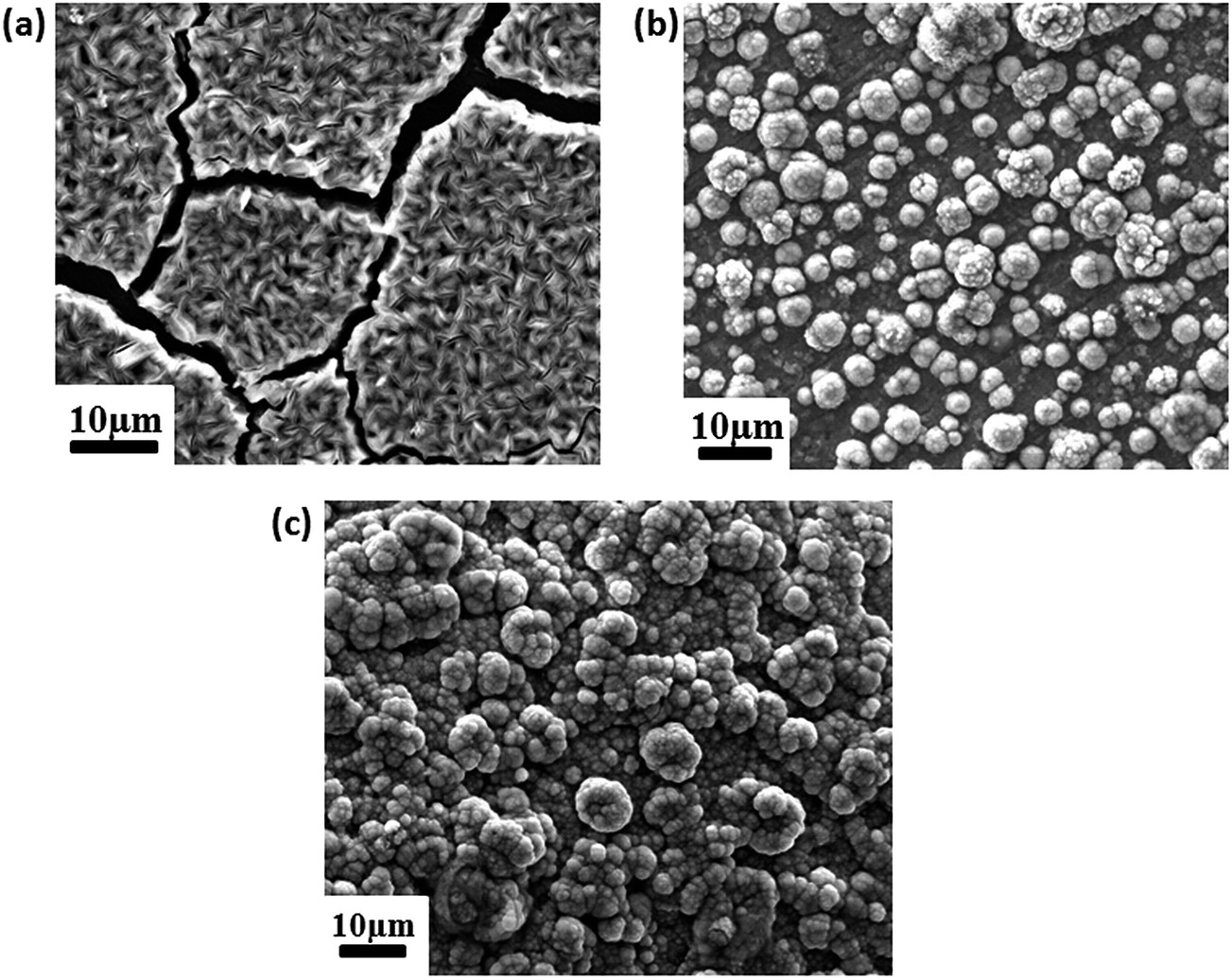 | ||
| Fig. 3 Representative SEM micrographs of (a) C (b) CF and (c) CFG coatings. | ||
The X-ray diffraction profiles of coatings are given in Fig. 4. Average crystallite size of the coatings was calculated using the FWHM of the highest intensity XRD peak and the Scherrer equation.29 The average crystallite size of the Cr coating obtained without formic acid (‘C’) was 30.37 nm. The average crystallite sizes for the Cr and Cr–graphene coatings (CF and CFG) obtained using the formic acid were 14.6 nm and 13.4 nm respectively. Addition of formic acid and graphene to the plating bath influenced the deposition kinetics and reduced the average crystallite size of the deposit. Addition of organic additives (formic acid) or second phase particles (graphene) provided more surface area for nucleation and also increased the deposition potential by blocking the active surface area of the cathode which enhanced nucleation rate and suppressed crystal growth.5,9,34,35 Increase in the nucleation rate and impeded crystal growth reduced the average crystallite size and enhanced the uniformity and compactness of the CF and CFG deposits. In Fig. 4 intense diffraction peaks (002), (100), (101), (102), (103) and (110) corresponding to Zn can be observed for the coating ‘C’. However, only (002) peak of Zn appears in the XRD profile obtained from CF and CFG coatings. CF and CFG coatings contain (110), (002) and (211) diffraction peaks of chromium. Addition of formic acid and graphene enhanced the Cr content in the deposits CF and CFG. Increased intensity of the (200) and (211) peaks for the CFG deposit when compared to the intensity of these peaks for the CF deposit revealed that the incorporation of graphene into the growing Cr metal matrix influenced the preferred orientation of the deposit.
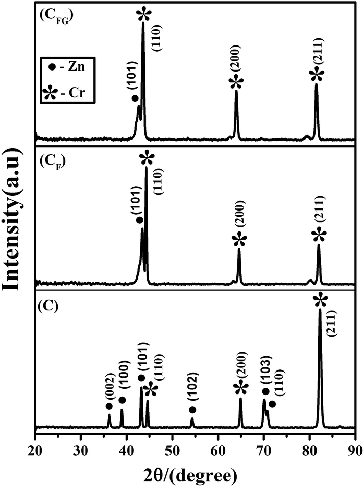 | ||
| Fig. 4 X-ray diffraction profile obtained from C, CF and CFG coatings. | ||
The potentiodynamic polarization curves recorded for Cr and Cr–graphene coatings are given in Fig. 5. The polarization curves were measured in 3.5% NaCl solution at room temperature. The working electrode was polarized to ±200 mV from their corresponding open circuit potential (OCP) value at the scan rate of 10 mV s−1. The corrosion parameters corrosion potential (Ecorr), corrosion current (Icorr) and corrosion rate (CR) were calculated from the obtained polarization curves/Tafel curves. Fig. 5 shows that the Tafel curve for Cr–graphene coating (CFG) is shifted towards more positive potential when compare to that of Cr coating (C and CF) or the Ecorr of the Cr–graphene coating is significantly higher than the Ecorr of graphene free Cr coating. The Ecorr of the coatings CFG, CF and C are −0.682 V, −0.762 and −0.983 V respectively. The corrosion potential analysis clearly shows that more potential is required to withdraw the electron from CFG composite coating compared to CF and C coating. The Icorr value for C, CF and CFG coatings are 51.67 μA cm−2, 29.57 μA cm−2 and 8.906 μA cm−2 respectively. The CR value of C, CF and CFG coatings are 33.42 μg h−1, 19.12 μg h−1 and 5.759 μg h−1 respectively. The decreased Icorr and CR values illustrates that the graphene incorporated Cr coating is more stable towards external aggressive media when compared to the pure Cr coating.
 | ||
| Fig. 5 Tafel polarization curves of C, CF and CFG composite coating in 3.5 wt% NaCl media. | ||
EIS analysis of the Cr and Cr–graphene coatings was carried at OCP of the corresponding deposit in the frequency range of 100 kHz to 10 mHz with the sinusoidal signal amplitude of 5 mV. The recorded EIS data is presented as Nyquist plot in Fig. 6. Two capacitive loops as shown in Nyquist plot reveals that the corrosion process consisted of two relaxation process/two time constants. However, the EIS data was curve fitted with 2RC electrical equivalent circuit (EEC) (Fig. 7) using ZSimp Win 3.21 software to collect the corrosion parameters. The capacitive elements in the EEC were replaced by constant phase element (CPE) to get better fitting. Contribution of each element in EEC in Fig. 7 is as follows:25,26
 | ||
| Fig. 6 Impedance Nyquist plot of C, CF and CFG composite coating (line representing measured data and symbols representing simulated data) and inset showing the enlarged impedance Nyquist plot. | ||
 | ||
| Fig. 7 Electrical equivalent circuit used for simulation of electrochemical impedance spectroscopy data. | ||
Re is the electrolyte resistance between the reference electrode and the surface of the working electrode.
The high frequency contribution (Qcoat–Rcoat) is ascribed to the dielectric character (Qcoat) of the coating that is reinforced by ionic conduction through its pores (Rcoat).
The low frequency contribution is attributed to the double layer capacitance (Qdl) at the electrolyte/coated surface interface at the bottom of the pores coupled with the charge transfer resistance (Rct).
The extent of anticorrosive behavior of the coating in aggressive media can be examined by considering the polarization resistance (Rp) i.e., the polarization resistance (Rp) which is the sum of Rcoat and Rct (i.e., Rp = Rcoat + Rct). The polarization resistance of CFG, CF and C coatings was 230 Ω cm2, 846 Ω cm2 and 1070 Ω cm2 respectively. The double layer capacitance of CFG, CF and C coatings were 25.7 μF cm−2, 28.5 μF cm−2 and 183.4 μF cm−2 respectively. The increase in polarization resistance of CFG composite coating compared to the Rp value of CF and C coating indicates that the graphene incorporated Cr coating is nobler towards the aggressive environment. The increased Qdl value of C coating indicates that the coating surface is more active towards corrosion hence the more charge is accumulated on the deposit C compared to CF and CFG which reduced the corrosion resistance property of the Cr coating. Electrochemical analysis of the Cr coatings reveals that the CF and CFG coatings are nobler than the deposit C. The galvanic coupling formed because of the high amount of Zn and the micro-cracks present reduces the anticorrosive property of the formic acid and graphene free Cr coating ‘C’. The addition of formic acid to the Cr(III) plating bath and the incorporation of graphene into growing Cr metal matrix improved the morphology, microstructure of the deposit in terms of reducing the micro-cracks by altering the kinetics of the electrodeposition process. Also, best corrosion resistance property is noticed for Cr coating obtained from Cr(III) plating bath containing formic acid and graph.
The organic additives are extensively used to obtain smooth and crack free Cr(III) deposits.7–9,36,37 In the present work, the morphology of the coating CFG is significantly enhanced compare to CF. The enhanced surface morphology of the Cr coating after the incorporation of graphene in to the growing Cr metal matrix suggests that the further optimization of bath composition with respect to graphene concentration may lead to the exclusion of organic additives from the plating composition and makes the process more eco-friendly. Chromium coating is also widely used to enhance the photothermal energy absorption.38–40 On the other hand; graphene has expansive application in solar cell technology because of its photo-absorption capacity.41–44 Hence, the incorporation of graphene in chromium metal matrix may significantly enhance the efficiency of solar cells by enhanced photothermal energy absorption. The present work describes the generation of crack free and anti corrosive chromium–graphene coatings and this opens the window to study the photothermal thermal conversion property of the Cr–G composite coatings.
Conclusion
The effect of graphene on the morphology, microstructure and consequently the electrochemical properties of metallic coatings is illustrated in this work. It is shown that the addition of graphene to electrodeposited metallic coatings significantly improves the corrosion resistance of the coating. This work also provides the electrodeposition parameter that can be used to produce graphene–Cr–ZnO nanoparticle composite coating. Cr(III) plating bath was used to deposit Cr coating on mild steel substrate. ZnO nanoparticles and graphene were also added into the Cr coating. ZnO nanoparticles were synthesized by the precipitation method followed by calcination. As synthesized and calcinated ZnO nanoparticles had an average Scherrer size of 23 nm. Graphene was synthesized by the electrochemical exfoliation method using SLS. The production of graphene from the electrochemical exfoliation process was confirmed from XRD, XPS and Raman based analysis. Average thickness of as-synthesized graphene was 4.1 ± 1.5 nm. The Cr coating produced without formic acid showed extensive cracking. Addition of formic acid substantially reduced the cracks in the Cr coating. The addition of graphene along with formic acid further enhanced the quality of the Cr coating with respect to the minimization of crack and coating compactness. Hillock structures were observed in the coating produced using formic acid these hillock structures increased considerably with the addition of graphene in the coating. Addition of graphene also altered the texture of the Cr-deposit. The addition of formic acid and graphene reduced the grain size of the Cr deposit when compared to the grain size of the Cr deposit synthesized without formic acid and graphene. Electrochemical studies revealed that corrosion resistance of Cr coating without additives is reduced because of the formation of micro-cracks. The coating containing graphene exhibited the highest corrosion resistance property when compared to pure Cr coating and coating produced using only formic acid. The corrosion potential analysis revealed that more potential is required to withdraw electron from CFG composite coating compared to CF and C coatings. Additionally, the increase in polarization resistance of CFG composite coating compared to the polarization resistance value of CF and C coating also indicated that the graphene incorporated Cr coating is nobler towards the aggressive environment.Acknowledgements
Authors acknowledge research funding received from Joint Advanced Technology Program (JATP), Indian Institute of Science, Bangalore, India and SERB government of India.References
- E. G. Vinokurov, A. M. Arsenkin, K. V. Grigorovich and V. V. Bondar, Prot. Met., 2006, 42, 290–294 CrossRef CAS.
- Z. Zeng, A. Liang and J. Zhang, Electrochim. Acta, 2008, 53, 7344–7349 CrossRef CAS.
- A. Liang and J. Zhang, Surf. Coat. Technol., 2012, 206, 3614–3618 CrossRef CAS.
- L. Fedrizzi, S. Rossi, F. Bellei and F. Deflorian, Wear, 2002, 253, 1173–1181 CrossRef CAS.
- X. He, Q. Zhu, B. Hou, C. Li, Y. Jiang, C. Zhang and L. Wu, Surf. Coat. Technol., 2015, 262, 148–153 CrossRef CAS.
- C. W. Chien, C. L. Liu, F. J. Chen, K. H. Lin and C. S. Lin, Electrochim. Acta, 2012, 72, 74–80 CrossRef CAS.
- I. Drela, J. Szynkarczuk and J. Kubicki, J. Appl. Electrochem., 1989, 19, 933–936 CrossRef CAS.
- F. I. Danilov, V. S. Protsenko, V. O. Gordiienko, S. C. Kwon, J. Y. Lee and M. Kim, Appl. Surf. Sci., 2011, 257, 8048–8053 CrossRef CAS.
- S. Surviliene, L. Orlovskaja and S. Biallozor, Surf. Coat. Technol., 1999, 122, 235–241 CrossRef CAS.
- S. Ke-Ning, H. X. Ning, Z. J. Hai and W. J. Ren, Wear, 1996, 196, 295–297 CrossRef CAS.
- M. A. Juneghani, M. Farzam and H. Zohdirad, Trans. Nonferrous Met. Soc. China, 2013, 23, 1993–2001 CrossRef CAS.
- S. Surviliene, V. Jasulaitiene, A. L. Oleksiak and V. A. Safonov, J. Appl. Electrochem., 2005, 35, 9–15 CrossRef CAS.
- J. Gao and J. Suo, Appl. Surf. Sci., 2011, 257, 9643–9648 CrossRef CAS.
- M. Noroozifar, M. K. Motlagh and Z. Yavari, International Journal of NanoScience and Nanotechnology, 2013, 9, 85–94 Search PubMed.
- I. A. Ovid'ko, Rev. Adv. Mater. Sci., 2013, 34, 1–11 Search PubMed.
- F. Bonaccorso, Z. Sun, T. Hasan and A. C. Ferrari, Nat. Photonics, 2010, 4, 611–622 CrossRef CAS.
- A. H. Castro Neto, F. Guinea, N. M. R. Peres, K. S. Novoselov and A. K. Geim, Rev. Mod. Phys., 2009, 81, 109–162 CrossRef CAS.
- E. Pop, V. Varshney and A. K. Roy, MRS Bull., 2012, 37, 1273–1281 CrossRef CAS.
- C. Y. Su, A. Y. Lu, Y. Xu, F. R. Chen, A. N. Khlobystov and L. J. Li, ACS Nano, 2011, 5, 2332–2339 CrossRef CAS PubMed.
- L. Yang, G. Wang, Y. Liu and M. Wang, Talanta, 2013, 113, 135–141 CrossRef CAS PubMed.
- W. Shen, Y. Yu, J. Shu and H. Cui, Chem. Commun., 2012, 48, 2894–2896 RSC.
- A. Roy, M. K. Punith Kumar and C. Srivastava, Chem. Phys. Lett., 2016, 646, 158–161 CrossRef CAS.
- D. Prasai, J. C. Tuberquia, R. R. Harl, G. K. Jennings and K. I. Bolotin, ACS Nano, 2012, 6(2), 1102–1108 CrossRef CAS PubMed.
- C. M. Praveen Kumar, T. V. Venkatesha and R. Shabadi, Mater. Res. Bull., 2013, 48(4), 1477–1483 CrossRef.
- M. K. Punith Kumar, M. P. Singh and C. Srivastava, RSC Adv., 2015, 5, 25603–25608 RSC.
- R. Berlia, M. K. Punith Kumar and C. Srivastava, RSC Adv., 2015, 5, 71413–71418 RSC.
- S. Surviliene, A. Cesuniene, R. Juskenas, A. Selskiene, D. Bucinskiene, P. Kalinauskas, K. Juskevicius and I. Jureviciute, Appl. Surf. Sci., 2014, 305, 492–497 CrossRef CAS.
- S. Surviliene, A. Cesuniene, V. Jasulaitiene and I. Jureviciute, Appl. Surf. Sci., 2014, 324, 837–841 CrossRef.
- A. J. Cooper, N. R. Wilson, I. A. Kinloch and R. A. W. Dryfe, Carbon, 2014, 66, 340–350 CrossRef CAS.
- A. L. Patterson, Phys. Rev., 1939, 56, 978–982 CrossRef CAS.
- M. Alanyalioglu, J. J. Segura, J. Oro-Sole and N. Casan-Pastor, Carbon, 2012, 50, 142–152 CrossRef CAS.
- L. Niu, M. Li, X. Tao, Z. Xie, X. Zhou, A. P. A. Raju, R. J. Young and Z. Zheng, Nanoscale, 2013, 5, 7202–7208 RSC.
- J. I. Paredes, S. Villar-Rodil, P. Solis-Fernandez, A. Martinez-Alonso and J. M. D. Tascon, Langmuir, 2009, 25(10), 5957–5968 CrossRef CAS PubMed.
- S. Zhang, B. Peng, S. Yang, Y. Fang and F. Peng, Int. J. Hydrogen Energy, 2013, 38, 13866–13871 CrossRef CAS.
- C. E. Lu, N. W. Pu, K. H. Houc, C. Chieh Tseng and M.-D. Ger, Appl. Surf. Sci., 2013, 282, 544–551 CrossRef CAS.
- N. V. Phuong, S. C. Kwon, J. Y. Lee, J. H. Lee and K. H. Lee, Surf. Coat. Technol., 2012, 206, 4349–4355 CrossRef CAS.
- V. S. Protsenko, F. I. Danilov, V. O. Gordiienko, S. C. Kwon, M. Kim and J. Y. Lee, Thin Solid Films, 2011, 520, 380–383 CrossRef CAS.
- T. K. Lee, D. H. Kim and P. C. Auh, Sol. Energy Mater. Sol. Cells, 1993, 29, 149–161 CrossRef CAS.
- J. Spitz, T. V. Danh and A. Aubert, Sol. Energy Mater., 1979, 1, 189–200 CrossRef CAS.
- J. M. Behaghel, S. Berthier, J. Lafait and J. Rivory, Sol. Energy Mater., 1979, 1, 201–213 CrossRef CAS.
- M. Vakili, S. M. Hosseinalipour, S. Delfani, S. Khosrojerdi and M. Karami, Sol. Energ., 2016, 131, 119–130 CrossRef CAS.
- M. Upadhyay Kahaly and U. Schwingenschlogl, Carbon, 2014, 77, 76–79 CrossRef CAS.
- X. Jia, X. Wang, Q. Meng, C. Yuan and Z. Zhou, Opt. Commun., 2016, 372, 172–179 CrossRef CAS.
- M. Vakili, S. M. Hosseinalipour, S. Delfani and S. Khosrojerdi, Sol. Energy Mater. Sol. Cells, 2016, 152, 187–191 CrossRef CAS.
| This journal is © The Royal Society of Chemistry 2016 |