
 Open Access Article
 This Open Access Article is licensed under a
 Creative Commons Attribution 3.0 Unported Licence
50–100 μm-thick pseudocapacitive electrodes of MnO2 nanoparticles uniformly electrodeposited in carbon nanotube papers†
Misato Narubayashi,
Zhongming Chen,
Kei Hasegawa and
Suguru Noda*
Department of Applied Chemistry, Waseda University, 3-4-1 Okubo, Shinjuku-ku, Tokyo 169-8555, Japan. E-mail: noda@waseda.jp
First published on 21st April 2016
Abstract
To overcome the tradeoff between the gravimetric capacitance and loading density of pseudocapacitive MnO2, we electrodeposited MnO2 nanoparticles on the carbon nanotube (CNT) surfaces in 18–37 μm-thick self-supporting CNT papers. We examined the electrodeposition conditions including constant potential, constant current, and potential pulses, and obtained MnO2–CNT hybrid electrodes containing MnO2 nanoparticles uniformly deposited at 60–90 wt% with an expanded CNT matrix. The MnO2–CNT hybrid electrode with a thickness of 62 μm, density of 1.09 g cm−3, areal mass of 6.75 mg cm−2, and 82 wt% MnO2 load showed a total gravimetric capacitance of 120 and 51 Ftotal gelectrode−1, volumetric capacitance of 131 and 56 Ftotal cm−3 and areal capacitance of 0.81 and 0.34 Ftotal cm−2 at scan rates of 2 and 200 mV s−1, respectively. The large thickness, moderately high mass density, and fairly conductive CNT matrix realized such high values of gravimetric, areal and volumetric capacitances that are important for practical devices.
Introduction
In recent years, owing to the growing demand for normalizing power fluctuations of solar and wind power generation and energy recovery in automobiles, electrochemical capacitors have attracted increasing attention as high power electrochemical energy storage devices. Activated carbon (AC), which has a huge specific surface area, is generally used as an active material for electric double layer capacitors, but there is limited room to enhance the capacitance by controlling the pore size distribution. To enhance the energy densities, pseudocapacitors using redox reactions of active materials such as metal oxides and conductive polymers, have been extensively studied. Ru compounds have been studied most extensively as active materials because they have high conductivity, proton mobility, and high capacitance in a wide potential window.1–3 It was reported that amorphous ruthenium oxide material calcined at 150 °C showed a maximum capacitance of 720 F g−1 in sulfuric acid electrolyte,1 and crystalline ruthenium oxide calcined at 200 °C showed a maximum capacitance of 710 F g−1 in KOH electrolyte.4 However, because ruthenium is a rare metal with a high cost and toxicity, less expensive materials have been studied.5 MnO2, with a high theoretical capacity of 1100 C g−1, is a promising candidate as an active material for commercial use because it is abundant, inexpensive, and environmentally friendly.6 However, it is necessary to use fine MnO2 particles with a high specific surface area because the conductivity of MnO2 is low and the redox reaction occurs preferentially on or near the surface during charge and discharge (eqn (1)).7| MnOOA ⇄ MnO2 + A+ + e− | (1) |
A very high gravimetric capacitance of 1200 F gMnO2−1 at 3 mV s−1 was confirmed,8 but for a very thin layer on indium tin oxide-coated glass substrate, resulting in a very small areal capacitance of 6.8 × 10⁻⁴ F cm−2.
Conventional capacitor electrodes are built on current collectors of metal foils on which active materials are attached by binders with conductive fillers (Fig. 1a). Although high gravimetric capacitance values have been reported for thin MnO2 electrodes (Fig. 1b), the capacitance per device is small because of the much larger mass of the current collector and separator compared with the active materials. In contrast, the gravimetric capacitance values of thick MnO2 electrodes are small (Fig. 1c). To utilize fine MnO2 particles at higher loads, their composites with carbon materials including carbon nanotubes (CNTs) or conductive polymers have also been studied.9–14
 | ||
| Fig. 1 Schematic illustrations of (a) conventional electric double layer capacitor electrode, (b) thin MnO2 electrode, (c) thick MnO2 electrode, and (d) the proposed MnO2–CNT hybrid electrode. (e) Gravimetric and areal capacitances of MnO2-based electrodes of previous works (blue open squares; the numbers represent the references)10–14 with scan rates of 1.25–20 mV s−1 and the present work (red closed circles) with a scan rate of 2 mV s−1. The capacitance values shown are for the total capacitance of the electrodes. | ||
CNTs are a conductive material with high aspect ratios and specific surface areas, high tensile strength with flexibility, and high thermal and chemical stability, and are expected to be applied in various electric and electronic devices. We have developed a fluidized bed chemical vapour deposition method that enables semi-continuous production of 200–400 μm-long few-wall CNTs with an average diameter of 6.5–8 nm, carbon purity of over 99 wt%, and a specific surface area of 400–440 m2 g−1.15,16 Such CNTs can form self-supporting papers with arbitrary thicknesses through a simple dispersion–filtration process without any binding additives. The CNT papers have a much larger surface area (2000–6000 cm2 for 20–60 μm-thick, 1 cm2 CNT paper) than metal foils (2 cm2 surface area for 1 cm2 foil) and can capture various active materials inside their nanometre-sized pores at loads much larger than their own mass. Positive electrodes of oxidized CNT papers for lithium batteries,17 positive electrodes of polymerized pyrene derivatives held in CNT papers for pseudocapacitors,18 and biomass-derived carbonaceous positive electrodes for lithium cells19 have been realized. We have also realized a self-supporting paper of AC (90 wt%) held by CNTs (10 wt%), which showed a three-times higher specific capacitance than the pure single-wall CNT electrodes20 and worked as a capacitor electrode not only in full contact but also in line contact to a metal mesh.21
The practical use of MnO2 as an active material in electrochemical capacitors requires: (1) deposition of fine MnO2 particles at a high density, (2) building of conductive paths to all MnO2 particles, and (3) electrodes that are sufficiently thick (several tens of micrometres). In this study, we aimed to fabricate electrodes using MnO2–CNT hybrids that have a high capacitance per mass and area of the electrode (Fig. 1d). Various methods such as hydrothermal synthesis,22 sol–gel method,23 electrostatic spray deposition,24 electrophoretic deposition,25 anodic oxidation,26 and cathodic reduction27 have been reported for making MnO2. Among them, electrodeposition26,27 is attractive because it forms conductive paths to every MnO2 particle. Uniform deposition of nickel oxide particles in vertically aligned CNT forests have been reported although the volumetric capacitance was small (1.26 F cm−3).28 Therefore, we electrodeposited MnO2 directly on CNT papers by anodically oxidizing Mn2+ ions using the CNT papers as a working electrode in a MnSO4 aqueous solution. A high potential is needed to deposit small MnO2 particles at a high density by enhancing their nucleation. But at the same time, high potential leads to a high deposition rate and diffusion-limited deposition, resulting in the preferential deposition of MnO2 on the outer surface of thick CNT papers. We examined electrodeposition at a constant potential (CP), at a constant current (CC), or by applying high potential pulses (hereafter “Pulse”), and analysed micro- and macroscopic structural changes and charge–discharge characteristics. The thick MnO2–CNT hybrids reported here have a higher areal capacitance than any previous report on MnO2 (Fig. 1e), expect for the very high value of 2.8 F cm−2 recorded at a very small scan rate of 0.05 mV s−1 for MnO2–CNT-textile with a high MnO2 load of 8.3 mg cm−2.14
Experimental
Preparation of the MnO2–CNT hybrid papers
Sub-millimetre-long few-wall CNTs (3–10 mg) synthesized by fluidized bed chemical vapour deposition16 were mixed with a 0.5 wt% sodium dodecylbenzene sulfonate aqueous solution (30–100 mL) and dispersed by ultrasonication (bath-type, 100 W, 30–100 min). The dispersed CNT solution was vacuum-filtrated on a membrane filter (polytetrafluoroethylene, pore size of 0.5 μm), and the CNT film on the membrane filter was washed by hot distilled water (80 °C), dried at 90 °C for 2 h under air, and then separated from the membrane filter using tweezers. The areal mass of the CNTs was controlled at 0.6–1.4 mg cm−2, yielding self-supporting CNT papers with a mass density of 0.25–0.48 g cm−3 and a thickness of 18–37 μm. MnO2–CNT hybrids were then prepared by electrodeposition using the condition reported by Jin et al.29 MnO2 were deposited on/in the CNT paper immersed in 0.6 M MnSO4/0.8 M H2SO4 aqueous electrolyte using the CNT paper as a working electrode, a graphite sheet as a counter electrode, and Ag/AgCl electrode (in 3 M NaCl aqueous solution) as a reference electrode. The electrodeposition was conducted either at CP, CC, or Pulse. The obtained electrodes were dried at 90 °C for 2 h under air.Characterization of the MnO2–CNT hybrids
The microstructure of the MnO2–CNT hybrids was characterized using a scanning electron microscope (SEM, Hitachi S-4800, Tokyo, Japan). The composition of the MnO2–CNT hybrids was evaluated using energy-dispersive X-ray spectroscopy (EDAX Genesis, AMETEK, Elancourt, France) equipped to SEM and mass change of the CNT papers. Their crystal structure was analysed using X-ray diffraction (Ultima III system, Rigaku, Akishima, Japan). Three-electrode cells were used to run cyclic voltammetry (CV), electrochemical impedance spectroscopy, and galvanostatic charge–discharge tests with a VMP3 potentiostat (Bio-Logic, Grenoble, France). The three-electrode cell consisted of a hybrid electrode as the working electrode, an AC–CNT hybrid film (90 wt% AC with 10 wt% CNTs, ∼200 μm in thickness)21 as the counter electrode and an Ag/AgCl electrode (in 3 M NaCl aqueous solution) as the reference electrode with 1 M Na2SO4 aqueous solution as the electrolyte. Structure and electrochemical performance are summarized for all and representative samples in ESI Tables S1 and S2, respectively.†Results and discussion
Rate process of electrodeposition and microstructure of the resulting MnO2 in CNT papers
Fig. S1† shows the typical current behaviour during electrodeposition of MnO2 at a potential range of 0.0–2.0 V. All potential values are shown vs. Ag/AgCl throughout this report. The equilibrium electrode potential of the CNT paper in the 0.6 M MnSO4/0.8 M H2SO4 aqueous electrolyte is 1.05 V. A rise in the current was observed twice at approximately 1.15 and 1.7 V, which possibly corresponds to the oxidation of Mn2+ ions (deposition of MnO2 onto the CNT paper) and further oxidation of MnO2 to MnO4− ions (resulting in the dissolution of deposited MnO2), respectively. The deposition rate of MnO2 is controlled by the potential of the CNT paper. We will discuss each aspect separately in detail below.Fig. 2a and b shows the current density profiles during electrodeposition at CP of 1.15, 1.20, and 1.30 V against the time of electrodeposition and the integrated electric charge, respectively. At all three potentials, a large current density was initially observed just after applying the electric potential, which quickly decayed in the first several seconds (Fig. 2a). The current density at 1.15 V became very small. Conversely, the current density increased for ∼5 and ∼2 min, became saturated, and decreased after ∼16 and ∼5 min at 1.20 and 1.30 V, respectively. Fig. 2c–i shows the plan-view SEM images of the surfaces of the CNT papers before (Fig. 2c) and after (Fig. 2d–i) electrodeposition. Flower-shaped particles formed inside the CNT papers (Fig. 2d, e and g) with increasing size and number density with time (Fig. 2d vs. 2e), and dense layers formed on the surface of the CNT papers after the decrease in the current density (Fig. 2f, h and i). These results suggest that the initial large current density after several seconds corresponds to the charge accumulation by the electric double layer on the CNT surface. The subsequent increase in current density corresponds to the increasing surface area of MnO2 by nucleation and growth of MnO2 particles and the final decrease in current density corresponds to the decreasing surface area and increasing electric resistance of the dense MnO2 layer. The increase in current density with the nucleation and growth of MnO2 particles indicates that the MnO2 deposition is preferred on the MnO2 surface rather than on the CNT surface. The interior of the CNT paper was filled with MnO2 particles uniformly from top to the bottom of the paper (Fig. 2j–m and S2a†), indicating that the Mn2+ diffuses into the CNT paper until the surface of the CNT paper is covered with a dense MnO2 layer. The MnO2 deposition accompanied the expansion of the CNT paper matrix, from 30 to 61–63 μm in thickness with the areal mass increase from 1.23 to 6.75 mg cm−2 and density increase from 0.41 to 1.09 g cm−3 during 10 min deposition at 1.20 V (Fig. 2j). As the deposition proceeds, the tortuosity of the CNT paper increases whereas the porosity decreases, thereby inhibiting the diffusion of Mn2+ and making the deposition of MnO2 preferential at the exterior of the paper and resulting in a dense MnO2 layer. Fig. 2b shows the change of current density with the integrated electric charge (corresponding to the amount of deposited MnO2). The current density decreased at a smaller integrated electric charge of ∼10 C cm−2 at 1.30 V than at ∼17 C cm−2 at 1.20 V, showing that less MnO2 nanoparticles can be deposited inside the CNT paper at higher potential owing to the accelerated formation of a dense layer. Comparison of Fig. 2e and g shows that smaller MnO2 particles were deposited at a higher number density at potentials of 1.30 V than at 1.20 V, indicating that a higher potential enhances the nucleation more than the growth of MnO2 particles. To realize high areal capacitance of the hybrid electrode, fine particles must be deposited at a high number density. Here arises a difficult tradeoff; a higher potential is needed to enhance the nucleation density of MnO2 particles, which at the same time causes concentration distribution of Mn2+ ions within the CNT papers, resulting in a dense MnO2 layer on the exterior of the CNT papers.
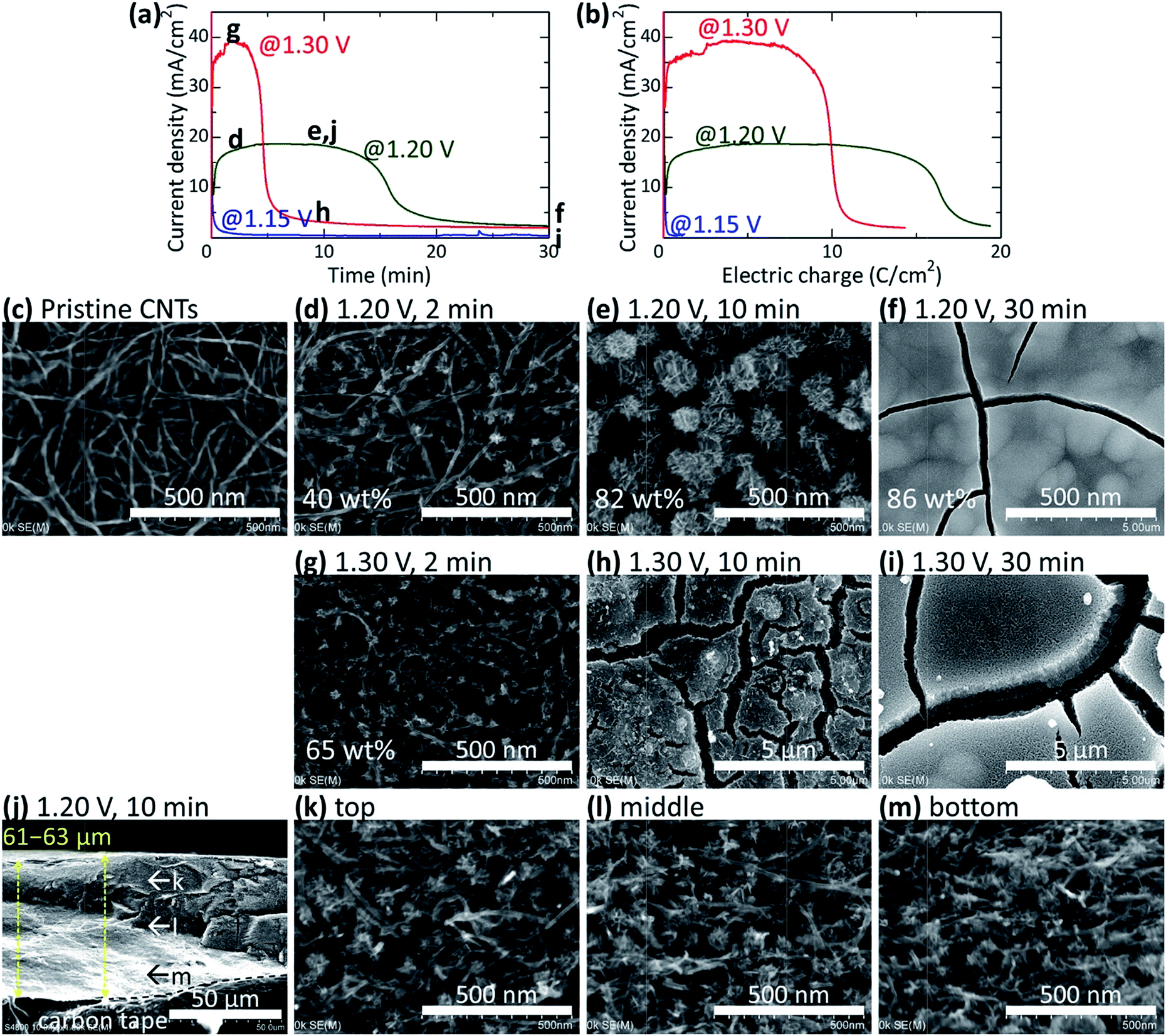 | ||
| Fig. 2 Electrodeposition of MnO2 in CNT papers (18–32 μm in thickness) at CP of 1.15, 1.20, and 1.30 V. Current change with (a) electrodeposition time and (b) integrated electric charge. SEM images of the surfaces of the CNT paper before (c) and after (d–i) electrodeposition. Cross-sectional SEM images of (e) is shown in (j–m). SEM-EDS elemental mapping images are shown for the cross-section in Fig. S2a.† | ||
To electrodeposit MnO2 particles in CNT papers uniformly at a high density, we investigated the control of the reaction rate by electrodeposition with CC. Fig. 3a and b shows potential profiles during electrodeposition at CC of 2 and 20 mA cm−2, respectively. At 2 mA cm−2, the potential changed slightly between 1.15 and 1.19 V for 180 min; it initially increased and then decreased and remained at a constant value. At 20 mA cm−2, the potential showed a similar change at ∼1.2 V for 10 min (less than 1/10 of that for 2 mA cm−2) and then increased abruptly to ∼1.5 V at ∼12 min. Fig. 3c shows the change in current density with integrated electric charge. It clearly shows that the MnO2 deposition proceeded at a higher potential with an abrupt potential increase with the larger current density of 20 mA cm−2. Fig. 3d–g shows plan-view SEM images of the surface of the MnO2–CNT hybrids after electrodeposition with CC of 2 mA cm−2. Particles grew continuously without forming a layer on the CNT paper surface even after a long electrodeposition time at 2 mA cm−2. Conversely, at 20 mA cm−2, small MnO2 particles formed at a higher density (Fig. 3h) and a dense layer formed on the surface of the CNT paper after deposition for 18 min (Fig. 3i). The initial increase, decrease, plateau, and abrupt increase (only with 20 mA cm−2) in the potential correspond to the charge accumulation by double-layer capacitance, the increased reaction area as a result of the formation of the MnO2 particles, the sufficient surface area for reaction and interspace for diffusion of the growing MnO2 particles, and the inhibited diffusion owing to the dense layer formation, respectively. It can be said that Mn2+ ions can diffuse uniformly even with a large amount of deposited MnO2 (22 C cm−2 and 87 wt%) when MnO2 is deposited slowly at 2 mA cm−2.
 | ||
| Fig. 3 Electrodeposition of MnO2 in CNT papers (28–34 μm) by CC of 2 and 20 mA cm−2. The potential change with (a and b) electrodeposition time and (c) integrated electric charge. The potential change is shown for different runs in (b). SEM images of the surfaces of the CNT paper with MnO2 electrodeposited at (d–g) 2 and (h and i) 20 mA cm−2. A cross-sectional SEM image of (h) is shown in (j–m). SEM-EDS elemental mapping images are shown for the cross-section in Fig. S2b.† | ||
Fig. 3j–m shows the cross-section of the film after electrodeposition at 20 mA cm−2 for 9 min (the same film as Fig. 3h). It indicates that MnO2 particles were uniformly electrodeposited inside the CNT paper. Increased current density (20 mA cm−2) and, thus, the overpotential (∼1.2 V) enhances the nucleation of MnO2 particles, initially making small MnO2 particles at high density (Fig. 3h and j). However, the potential increases at ∼12 min owing to the formation of a surface layer (Fig. 3i); the accessible surface area of MnO2 for Mn2+ ions decreases and the overpotential increases to balance the constant current.
To electrodeposit fine MnO2 particles at a high density, next we investigated intermittently applying high potential pulses. We expected the nucleation of MnO2 particles to be accelerated by the high potential, and a uniform deposition of fine MnO2 particles to be achieved by allowing the Mn2+ ions to diffuse into the CNT paper uniformly during the rests between the pulses. Fig. 4a and b shows typical time profiles of the applied potential and resulting current density. Fig. 4c–f shows the SEM images of the electrode surface after pulse-deposition by repeatedly applying potential pulses of 2.0 V for 0.5 s at 10 s intervals (15–60 times). Small MnO2 particles covered the CNT bundles after 15 pulses, and CNT–MnO2 core–shell wires became thicker after more pulses. SEM images and EDS elemental mapping of the cross-section (Fig. 4g–j and S2c†) show that MnO2 was uniformly electrodeposited inside the CNT paper. In the case of CC, the small current and thus the low potential nucleated MnO2 particles at a low density resulting in large particles (Fig. 3). Conversely, the high potential pulse-deposition enhanced the nucleation of MnO2 particles owing to a high overpotential, resulting in small MnO2 particles at a very high density covering the CNT surfaces.
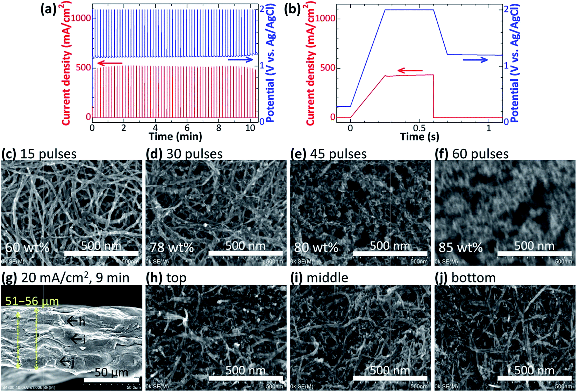 | ||
| Fig. 4 Electrodeposition of MnO2 in CNT papers (32–37 μm) by applying potential pulses of 2.0 V. Time profiles of the applied potential and resulting current density for (a) the whole deposition and (b) a single pulse. (c–f) SEM images of the surface of the CNT papers with MnO2 electrodeposited with 15–60 pulses. (g–j) A cross-sectional SEM image of the MnO2–CNT hybrid shown in (e). SEM-EDS elemental mapping images for the cross-section are shown in Fig. S2c.† | ||
Fig. S3† shows the XRD spectra of the CNT paper and the composite electrodes after electrodeposition by CP, CC, and Pulse. Peaks corresponding to (100), (101), (102), and (110) of akhtenskite-type MnO2 are present in all the spectra. The peaks are sharp for MnO2 electrodeposited by CC, and the full width at half maximum (FWHM) increases in the order of CC, CP, and Pulse, showing that MnO2 electrodeposited at higher potential results in poorer crystallinity. The peaks of the sample prepared by applying Pulse shifted to lower angles, showing increased lattice spacings and suggesting inferior crystallinity because of the rapid MnO2 deposition at a high overpotential.
Electrochemical performances of MnO2–CNT hybrid electrodes
The electrochemical performance of the MnO2–CNT hybrid electrodes was examined using a three-electrode cell with 1 M Na2SO4 aqueous solution at a potential range of 0–0.8 V. Fig. S4† shows typical CV curves of the MnO2–CNT electrode electrodeposited by CP at 1.20 V for 10 min. The CV curves show rectangular shapes at low scan rates, which are typical of capacitor electrodes and suggest that sufficient electric conduction pathways are provided by the CNT matrix. At higher scan rates ≥100 mV s−1, their shapes change to parallelogram, resulting in decreasing capacitances with scan rates.Fig. 5 shows the rate performances of the MnO2–CNT hybrid electrodes electrodeposited by CP (Fig. 5a–c), CC (Fig. 5d–f), and Pulse (Fig. 5g–i). The MnO2-based capacitances (Fig. 5c, f and i) were estimated by subtracting the capacitance of the CNT paper from the total capacitance of the electrodes (Fig. 5b, e and h). Because the CNT papers lose their exposed surface as MnO2 is deposited, the contribution of the CNTs is overestimated and the actual MnO2-based capacitance should be higher.
 | ||
| Fig. 5 Rate performances of the hybrids with MnO2 electrodeposited by CP (a–c), CC (d–f), and Pulse (g–i) on CNT papers of ∼30 μm in thickness (0.57–1.28 mg cm−2). (a, d and g) Areal capacitances for the total films (total capacitance divided by electrode area). (b, e and h) Gravimetric capacitances for the total film (total capacitance divided by electrode mass). (c, f and i) Gravimetric capacitances for MnO2 (the capacitance of pristine CNTs was subtracted from the total capacitance, and then divided by the mass of MnO2). | ||
The total areal capacitance at 1 mV s−1 of the MnO2–CNT hybrids prepared by CP at 1.20 V increased significantly with deposition time, from 0.02 F cm−2 for pristine CNTs to 1.08 F cm−2 after 30 min deposition (Fig. 5a). The total gravimetric capacitance at 1 mV s−1 increased from 22 Ftotal gelectrode−1 for pristine CNTs to 124 Ftotal gelectrode−1 after 10 min deposition, but it changed little at a low scan rate and decreased at a high scan rate after a 30 min deposition (Fig. 5b). The MnO2-based capacitance was largest after a 2 min deposition (170 and 131 FMnO2 gMnO2−1 at 1 and 200 mV s−1, respectively) and decreased monotonically after deposition for 2 to 30 min (Fig. 5c) owing to the increased particle size of MnO2 (Fig. 2). Previous reports mainly discuss the gravimetric capacitance of MnO2, for which the largest value can be obtained for a small MnO2 load. However, the total capacitance of an electrode is more important for practical applications, and the largest gravimetric and areal capacitances can be obtained for a moderate (10 min) and large (30 min) load of MnO2, respectively. The MnO2–CNT hybrid deposited at 1.20 V for 10 min had a large thickness of 62 μm, high areal mass of 6.75 mg cm−2 and high mass density of 1.09 g cm−3, yielding a moderate total gravimetric capacitance of 120 and 51 Ftotal gelectrode−1, high volumetric capacitance of 131 and 56 Ftotal cm−3 and high areal capacitance of 0.81 and 0.34 Ftotal cm−2 at scan rates of 2 and 200 mV s−1, respectively.
The changes in the capacitance values for the hybrids prepared by CP at 1.30 V were different from those prepared by CP at 1.20 V. The total areal capacitances were largest (0.48 F cm−2 at 1 mV s−1) after a 2 min deposition and decreased after further deposition for 10 and 30 min (Fig. 5a). Additional deposition of over 10 min resulted in continuous film formation on the electrode surface (Fig. 2h and i), which inhibited the use of MnO2 particles inside the CNT papers. A similar change was observed for the total and MnO2-based gravimetric capacitances (Fig. 5b and c).
For the MnO2–CNT hybrids prepared by CC at 2 mA cm−2, the total areal capacitance increased with the deposition time (and thus MnO2 load) (Fig. 5d). The total gravimetric capacitance increased with deposition time, showing a maximum at 90 min and decreasing at 180 min (Fig. 5e). The MnO2-based gravimetric capacitance decreased monotonically with increasing deposition time owing to the monotonic increase in the particle size of MnO2 (Fig. 3d–g). The capacitances of the materials obtained by CC at 20 mA cm−2 were significantly larger than those obtained by CC at 2 mA cm−2 (Fig. 5d–f). The total electric charge for electrodeposition was the same between 2 mA cm−2 for 90 min and 20 mA cm−2 for 9 min and between 2 mA cm−2 for 180 min and 20 mA cm−2 for 18 min, yielding similar content of MnO2 in the hybrid films (75 and 81 wt% for the former and 87 and 87 wt% for the latter). The significantly high capacitance of the hybrids obtained by CC at 20 mA cm−2 was attributed to the smaller MnO2 particles at higher density (Fig. 3h) although a continuous film covers the electrode surface after deposition for 18 min (Fig. 3i). When we carefully compare the two hybrids at 20 mA cm−2, both the total and MnO2-based capacitances were higher for the hybrid deposited for 9 min than that for 18 min at high scan rates (≥50 mV s−1). The capacitance tends to be limited by the ionic diffusion in electrolyte because more ions need to diffuse through the pores of smaller volume and/or larger tortuosity in the hybrids with higher MnO2 content. The best conditions change for the targeted capacitances (i.e., areal or gravimetric), and in view of gravimetric capacitance, the best hybrid obtained by CC at 20 mA cm−2 for 9 min (Fig. 5e) showed a similar performance with the best hybrid obtained by CP at 1.20 V for 10 min (Fig. 5b). This result is reasonable if we consider the similar electrodeposition conditions between the former (81 wt% MnO2 at 20 mA cm−2 and ∼1.2 V for 9 min, Fig. 3b and h) and the latter (82 wt% MnO2 at 18–19 mA cm−2 and 1.20 V for 10 min, Fig. 2a and e).
For the MnO2–CNT hybrids prepared by applying Pulse (Fig. 5g), the total areal capacitance also increased with the number of pulses and thus the MnO2 load, but did not increase as much compared with the hybrids prepared by CP and CC. Their total gravimetric capacitances were fairly high for all of the conditions between 15 and 60 pulses (Fig. 5h); 96–105 and 44–65 Ftotal gelectrode−1 at 1 and 200 mV s−1, respectively. Their MnO2-based gravimetric capacitance showed some decrease with increasing number of pulses; from 154 to 109 and from 100 to 49 FMnO2 gMnO2−1 at scan rates of 1 and 200 mV s−1 for 15 and 60 pulses, respectively. Because of the smaller MnO2 particles electrodeposited by Pulse, the MnO2-based gravimetric capacitance did not change much (Fig. 5i), resulting in almost constant total gravimetric capacitances (Fig. 5h) and increasing total areal capacitances (Fig. 5g) with increasing number of pulses and thus MnO2 load. But the inferior crystallinity of the MnO2 particles prepared by Pulse compared with those prepared by CP and CC (Fig. S3†) may have cancelled the advantage of small particle size, resulting in moderate MnO2-based gravimetric capacitance values. Further enhancement of the capacitances could be expected by improving the crystallinity of MnO2 by adjusting the potential more carefully.
Fig. 6 summarizes the capacitance of our MnO2–CNT hybrid electrodes electrodeposited under various conditions. Fig. 6a clearly shows that the total areal capacitance increased with MnO2 load under most conditions, and largest values were achieved for the films by CP at 1.20 V and CC at 20 mA cm−2. Fig. 6b shows that the total gravimetric capacitance increased with MnO2 load of ≤3 mg cm−2 but became saturated or even decreased for higher MnO2 load. The capacitance enhancement is more significant than the mass increase for small MnO2 load but the mass increase becomes more significant than capacitance enhancement for large MnO2 load. Fig. 6c shows that the MnO2-based gravimetric capacitance was very high for very small MnO2 load (346 FMnO2 gMnO2−1 at 2 mV s−1 for a hybrid with MnO2 load of 0.12 mg cm−2 and 8.5 wt%), which decreased monotonically to 30–150 FMnO2 gMnO2−1 with increasing MnO2 load. The utility ratio of MnO2 decreased with increasing MnO2 load owing to the increasing particle size, increasing tortuosity, decreasing porosity, and/or continuous film formation (Fig. 2–4). Fig. 6d shows the film performance plotted against the capacitance values that are important for practical application; total areal capacitance vs. total gravimetric capacitance. The hybrids deposited by CP at 1.20 V for 10 and 30 min and those deposited by CC at 20 mA cm−2 for 9 and 18 min showed high gravimetric and areal capacitances at low scan rates of 2–20 mV s−1 owing to the high load. In contrast, they showed a decreased capacitance at a high scan rate of 200 mV s−1 owing to the large particle size and/or continuous surface layer of MnO2 (Fig. 3 and 4). The hybrids deposited by applying Pulse with 45 and 60 pulses showed moderately high gravimetric and areal capacitances. Fig. 6e shows the film performance plotted against the total areal capacitance and MnO2-based gravimetric capacitance. It is clear that the MnO2-based gravimetric capacitance, which is often called “specific capacitance” and reported as a primary property, is in a tradeoff relationship with the areal capacitance that is important for practical applications. Fig. 1e shows a similar plot comparing the present work with previous reports in a logarithmic scale with a different definition of the gravimetric capacitance (i.e., MnO2-based capacitance divided by MnO2 mass for Fig. 6e and total capacitance divided by MnO2 mass for Fig. 1e). Encouraging values that were reported for MnO2-based gravimetric capacitance were realized by very small MnO2 loads, resulting in very small total areal capacitance values. Our electrodes with fine MnO2 particles uniformly electrodeposited in 18–37 μm thick CNT paper realized areal capacitance of ∼1 F cm−2, which is much higher than most of previously reported values.
 | ||
| Fig. 6 Summary of the capacitance of MnO2–CNT hybrid electrodes deposited under various conditions. (a) Total areal capacitance, (b) total gravimetric capacitance, and (c) MnO2-based gravimetric capacitance were plotted against MnO2 load. Plots show the capacitance values at a scan rate of 20 mV s−1, and error bars show the values at scan rates of 2 and 200 mV s−1. Total areal capacitance was plotted against (d) total gravimetric capacitance and (e) MnO2-based gravimetric capacitance. Capacitances at scan rates of 2, 20, 200 mV s−1 of the same film were plotted with the same symbol and connected with a line. | ||
Stability and performance changes of the MnO2–CNT hybrid electrodeposited by CP at 1.20 V for 10 min were tested by galvanostatic charge–discharge cycling between 0.0 and 0.8 V. The symmetric shape of the charge–discharge profiles is very close to that expected for an ideal capacitor, with small IR (current–resistance) drops (Fig. S5a†). As for the cycle stability, the electrode showed some decay in capacitance to ∼90% after 5000 cycles (Fig. S5b†).
Conclusions
MnO2–CNT hybrid electrodes were fabricated by electrodepositing MnO2 on self-supporting CNT paper as a three dimensional current collector. For uniform electrodeposition of MnO2 particles inside the 18–37 μm-thick CNT papers, we considered diffusion and reaction processes of Mn2+ ions. A high potential enhanced the reaction, especially nucleation of MnO2 particles, yielding small particles at high density. But the process was diffusion-controlled, yielding a dense MnO2 layer on the exterior surface of the electrodes. Such electrodes were not suitable for capacitor electrodes because of the inhibited ionic diffusion by the dense layer during capacitor operation. In contrast, a low potential made the reaction slow, making the process reaction controlled and realizing uniform MnO2 deposition within the CNT matrix owing to the sufficient Mn2+ diffusion. But the low potential made the nucleation of MnO2 particles slow, yielding large particles at a low density. Such electrodes did not show high capacitance owing to the low electric conductivity of MnO2 and slow ionic diffusion in MnO2. To overcome the tradeoff between the uniformity and particle size/density, we examined pulse electrodeposition, in which high potential pulses were intermittently applied to deposit fine MnO2 particles at high density and allow the Mn2+ ions to diffuse during the intervals. MnO2 was deposited uniformly with amounts increasing roughly proportional to the charge, and we obtained electrodes with MnO2 content of ≥80 wt% (and thus CNT ≤ 20 wt%) without the formation of a dense MnO2 layer on the electrode surface.For the electrodes using 18–37 μm-thick CNT paper, the best performance was achieved when MnO2 was deposited by CP of 1.20 V for 10 min. The resulting MnO2–CNT hybrid had a large thickness of 62 μm, high areal mass of 6.75 mg cm−2 and high mass density of 1.09 g cm−3, yielding a moderate total gravimetric capacitance of 120 and 51 Ftotal gelectrode−1, high volumetric capacitance of 131 and 56 Ftotal cm−3 and high areal capacitance of 0.81 and 0.34 Ftotal cm−2 at scan rates of 2 and 200 mV s−1, respectively. The MnO2–CNT hybrid prepared by Pulse had small particles at high density uniformly dispersed within the CNT matrix, but showed moderate capacitance possibly owing to the inferior crystallinity resulting at the high applied potential of 2.0 V. We are trying to improve the crystallinity of the small MnO2 particles deposited uniformly at high density by adjusting the potential used for the pulse deposition.
Acknowledgements
The authors gratefully acknowledge Prof. Tetsuya Osaka and Prof. Toshiyuki Momma at Waseda University for their support in initiating this work. This work was financially supported by Grant-in-Aid for Scientific Research (A) (no. 25249111) from the Japan Society for the Promotion of Science and by the Advanced Low Carbon Technology Research and Development Program from Japan Science and Technology Agency, Japan.Notes and references
- J. P. Zheng, P. J. Cygan and T. R. Jow, J. Electrochem. Soc., 1995, 142, 2699 CrossRef CAS.
- D. B. Rogers, R. D. Shannon, A. W. Sleight and J. L. Gillson, Inorg. Chem., 1969, 8, 841 CrossRef CAS.
- S. Hadi-Jordanov, H. Angerstein-Kozlowska, M. Vuković and B. E. Conway, J. Electrochem. Soc., 1978, 125, 1471 CrossRef.
- N.-L. Wu, S.-L. Kuo and M.-H. Lee, J. Power Sources, 2002, 104, 62 CrossRef CAS.
- G. Wang, L. Zhang and J. Zhang, Chem. Soc. Rev., 2012, 41, 797 RSC.
- G. Yu, L. Hu, N. Liu, H. Wang, M. Vosgueritchian, Y. Yang, Y. Cui and Z. Bao, Nano Lett., 2011, 11, 4438 CrossRef CAS PubMed.
- M. Toupin, T. Brousse and D. Belanger, Chem. Mater., 2004, 16, 3184 CrossRef CAS.
- M. Yano, S. Suzuki, M. Miyayama and M. Ohgaki, Solid State Ionics, 2013, 233, 32 CrossRef CAS.
- G. Wang, L. Zhang and J. Zhang, Chem. Soc. Rev., 2012, 41, 797 RSC.
- S. R. Sivakkumar, J. M. Ko, D. Y. Kim and G. C. Wallace, Electrochim. Acta, 2007, 52, 7377 CrossRef CAS.
- K.-W. Nam, C. Lee, X. Yang, B. W. Cho, W. Yoon and K. Kim, J. Power Sources, 2009, 188, 323 CrossRef CAS.
- Y. Hou, T. Cheng, T. Hobson and J. Liu, Nano Lett., 2010, 10, 2727 CrossRef CAS PubMed.
- J.-H. Kim, K. H. Lee, L. J Overzet and G. S. Lee, Nano Lett., 2011, 11, 2611 CrossRef CAS PubMed.
- L. Hu, W. Chen, X. Xie, N. Liu, Y. Yang, H. Wu, Y. Yao, M. Pasta, H. N. Alshareef and Y. Cui, ACS Nano, 2011, 5, 8904 CrossRef CAS PubMed.
- D. Y. Kim, H. Sugime, K. Hasegawa, T. Osawa and S. Noda, Carbon, 2011, 49, 1972 CrossRef CAS.
- Z. Chen, D. Y. Kim, K. Hasegawa, T. Osawa and S. Noda, Carbon, 2014, 80, 339 CrossRef CAS.
- S. W. Lee, B. M. Gallant, Y. Lee, N. Yoshida, D. Y. Kim, Y. Yamada, S. Noda, A. Yamada and Y. Shao-Horn, Energy Environ. Sci., 2012, 5, 5437 CAS.
- J. C. Bachman, R. Kavian, D. J. Graham, D. Y. Kim, S. Noda, D. G. Nocera, Y. Shao-Horn and S. W. Lee, Nat. Commun., 2015, 6, 7040 CrossRef PubMed.
- T. Liu, R. Kavian, Z. Chen, S. S. Cruz, S. Noda and S. W. Lee, Nanoscale, 2016, 8, 3671 RSC.
- R. Quintero, D. Y. Kim, K. Hasegawa, Y. Yamada, A. Yamada and S. Noda, RSC Adv., 2015, 5, 16101 RSC.
- R. Quintero, D. Y. Kim, K. Hasegawa, Y. Yamada, A. Yamada and S. Noda, RSC Adv., 2014, 4, 8230 RSC.
- W. Xiao, H. Xia, J. Y. H. Fuh and L. Lu, J. Power Sources, 2009, 193, 935 CrossRef CAS.
- A. Burke, J. Power Sources, 2000, 91, 37 CrossRef CAS.
- M. Min, K. Machida, J. H. Jang and K. Naoi, J. Electrochem. Soc., 2006, 153, A334 CrossRef CAS.
- I. Zhitomirsky, M. Cheong and J. Wei, JOM, 2007, 59, 66 CrossRef CAS.
- S.-L. Kuo and N.-L. Wu, J. Electrochem. Soc., 2006, 153, A1317 CrossRef CAS.
- N. Nagarajan, H. Humadi and I. Zhitomirsky, Electrochim. Acta, 2006, 51, 3039 CrossRef CAS.
- Y. Jiang, P. Wang, X. Zang, Y. Yang, A. Kozinda and L. Lin, Nano Lett., 2013, 13, 3524 CrossRef CAS PubMed.
- Y. Jin, H. Chen, M. Chen, N. Liu and Q. Li, ACS Appl. Mater. Interfaces, 2013, 5, 3408 CAS.
Footnote |
| † Electronic supplementary information (ESI) available. See DOI: 10.1039/c6ra06433g |
| This journal is © The Royal Society of Chemistry 2016 |