 Open Access Article
High purity pressurised hydrogen production from syngas by the steam-iron process
Gernot Voitic*a,
Stephan Nestla,
Karin Mallia,
Julian Wagnerbc,
Brigitte Bitschnaud,
Franz-Andreas Mautnerd and
Viktor Hackera
aGraz University of Technology, Institute of Chemical Engineering and Environmental Technology, NAWI Graz, Inffeldgasse 25/C/II, 8010 Graz, Austria. E-mail: gernot.voitic@tugraz.at
bGraz Centre for Electron Microscopy, Graz, Austria
cInstitute for Electron Microscopy and Nanoanalysis, Graz University of Technology, Graz, Austria
dInstitute of Physical and Theoretical Chemistry, Graz University of Technology, Graz, Austria
First published on 23rd May 2016
Abstract
The production of hydrogen in a fixed bed reactor at a maximum pressure of 50 bar by oxidising an oxygen carrier (Fe2O3/Al2O3/CeO2) with 0.06 g min−1 of steam at 1023 K is discussed. Reductions were performed with synthesis gas at ambient pressure and 1023 K for 90 minutes. The influences of the elevated system pressure on the carbon contamination, the quantification of the contaminations in the produced hydrogen and the oxygen carrier conversion are analysed. The results show that small amounts of carbon depositions are formed during the reduction, which are re-oxidised with steam leading to the contamination of the hydrogen. The hydrogen purity obtained in the experiments is within the range of 99.958% to 99.999% with CO as the main impurity. The amount of contaminations as a result of the oxidation of the solid carbon is not influenced by the elevated system pressure, which confirms the suitability of the reformer steam-iron process in a fixed bed to produce pressurised hydrogen directly from a hydrocarbon feed. The oxygen carrier conversion displays an initial drop followed by a slightly linear decrease. Air-oxidations revealed a regeneration effect on the oxygen carrier conversion, which reversed a part of the conversion losses.
1. Introduction
The recent scientific reports on global warming and on the possible impacts on nature and humanity urge us to react decisively. Anthropogenic CO2 emissions were specified as one of the main sources for climate changes.1,2 Hydrogen, used as fuel, can be a big contribution to the reduction of greenhouse gas emissions. However, hydrogen is a secondary energy carrier, which means it has to be produced out of other primary energy sources. Thus, hydrogen can only be considered environment-friendly if its energy resource and the whole conversion process do not inherit an undesirable carbon dioxide balance. Today more than 96% of the hydrogen is produced out of fossil fuels.3 The steam reforming of hydrocarbons is currently the most common application because of its reliable technology, its low production costs and the low cost resources.4,5 The steam reforming is usually followed by a 2-step water-gas-shift process and final CO clean-up.6 The whole reforming and purification process is very efficient in large scale plants under stable operation conditions.7 Thus, hydrogen is nowadays produced in centralised plants transported over long distances by trucks and stored on-site in huge quantities.8 This distribution and storage logistic significantly contributes to the production costs of hydrogen.9As an alternative, decentralised small-scale chemical looping water splitting (CLWS), a modification of chemical looping combustion (CLC), is a very promising technology to produce pure hydrogen by cyclic operation. The technology separates the reduction reactions with carbonaceous components from the oxidation with steam, which yields very pure hydrogen.
At Graz University of Technology the reformer sponge iron cycle (RESC) was introduced,10,11 followed by an extensive evaluation of the thermodynamic potential of the process and test series for component development.12,13 Finally, this led to the development of the reformer steam-iron process, which offers the perspective of a decentralised on-demand hydrogen production out of emission-free hydrocarbon feedstocks (e.g. biogas). This technology addresses both described issues by:
- The production of environment-friendly hydrogen utilising renewable hydrocarbons to reduce the global CO2 emissions.
- Decentralised production logistics to reduce hydrogen transport and storage demand.
The reformer steam-iron process combines the conventional steam reforming (eqn (1)) with the steam-iron process (eqn (2)–(5)). Both processes are performed in fixed beds, which are mutually placed inside one tubular reactor (Fig. 1). A hydrocarbon feedstock is converted by heterogeneous catalysis in the reforming bed to a hydrogen-rich synthesis gas (eqn (1)). The syngas is directly used to reduce the iron-based oxygen carrier (eqn (2)–(4)). The reduction reaction reduces iron oxide (hematite Fe2O3 or magnetite Fe3O4) to a more reduced state (wustite FeO or iron Fe). In the subsequent process step steam re-oxidises the oxygen carrier by releasing hydrogen (eqn (5)). The oxidation with steam can only oxidise iron to magnetite (Fe3O4), which means that all reaction cycles after the first are performed between magnetite and iron/wustite (eqn (3) and (4)). The oxidation with air or oxygen leads to the formation of the initial state (hematite) of the oxygen carrier (eqn (6)).
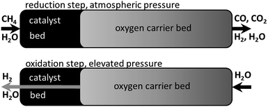 | ||
| Fig. 1 The reformer steam-iron process schematic with a reduction at atmospheric pressure and methane as fuel and a subsequent oxidation at elevated pressure in a fixed bed reactor. | ||
In previous publications our group discussed the optimisation of the reformer steam-iron process by performing the oxidation at elevated pressure to produce pressurised hydrogen directly without additional gas compression, which significantly raises the efficiency of decentralised hydrogen production logistics.14,15 Thermodynamic simulations showed that the steam reforming and reduction on the other hand must be performed at ambient pressure to achieve a high conversion of the reducing agents.16
The effects of an increased system pressure in a CLC system have been investigated by several other work groups.17–21 However their work primarily focused on the reduction behaviour or the whole cycle under pressure and the oxidation was performed with air/oxygen. Regarding the pressure behaviour of oxygen carrier in cyclic redox systems two conflicting insights can be found in the literature. Several publications report a negative influence of an elevated pressure during redox reactions of different types of oxygen carrier.18,22–24 Reduced reaction rates were measured, which resulted in extended kinetically controlled regimes. Hence the reaction time is increased. The impact of pressure on the internal structure of the oxygen carrier is a probable explanation. A higher risk of solid carbon formation by a pressure elevation was also reported.23 On the other hand some work19–21 suggests positive effects off higher system pressures by increasing the carbon conversion indicated by a higher outlet-CO2 concentration. Thus a lower reduction degree of the oxygen carrier is achieved. The improved reduction was observed from 0.1 to 0.5 MPa, while at higher pressure levels a worsening became apparent. The usual operation procedure in chemical looping systems maintains the pressurised condition during the complete cycle (reduction and oxidation), whereas the reformer-steam iron process benefits from the reduction under atmospheric conditions and the oxidation under elevated system pressure. Thus the literature survey shows an incomplete knowledge of the pressure influences on chemical looping hydrogen systems.
In our most recent work we explained the feasibility of the pressurised oxidation at 22 bar without any negative impact on the conversion efficiency of the reduction and oxidation reactions and on the mechanical stability of the oxygen carrier, with hydrogen as the only reducing component.25
The present work focuses on the reduction of an iron based oxygen carrier with a synthesis gas at ambient pressure, followed by an oxidation at different elevated pressures of up to 50 bar. The aim of this work is to study (i) influences of an increased system pressure on the hydrogen purity regarding carbon contamination, (ii) the characterisation and quantification of the contaminations, (iii) the analysis of the oxygen carrier conversion regarding efficiency and stability and (iv) the verification of the feasibility of the process at elevated oxidation up to 50 bar. To the best of our knowledge this was not investigated by other groups before and is expected to further enhance the applicability of the reformer-steam iron process for commercialised decentralised hydrogen production.
| CmHn + mH2O → mCO + (m + (½)n)H2 | (1) |
| Fe2O3 + 3(H2/CO) → 2Fe + 3(H2O/CO2) | (2) |
| Fe3O4 + H2/CO → 3FeO + H2O/CO2 | (3) |
| FeO + H2/CO → Fe + H2O/CO2 | (4) |
| 3Fe + 4H2O → Fe3O4 + 4H2 | (5) |
| 2Fe3O4 + ½O2 → 3Fe2O3 | (6) |
2. Experimental
a. Pressure test equipment and operation procedures
The cyclic experiments were performed in a modified test rig for catalytic analysis (Fig. 2). The main component is a fixed bed tubular reactor (alloy 617, OD 25 mm, ID 15.26 mm, length 350 mm), which can withstand a maximum pressure of 100 bar at temperatures of up to 1123 K. The reactor is filled with the pelletised oxygen carrier. A thermocouple is placed inside the oxygen carrier bed. Both reactor ends were filled with inert materials to preheat the reaction gases and to prevent movement inside the reactor. The steam-carrying parts of the system were heated with heating-cords to 573 K to prevent steam condensation at higher system pressure. At the system outlet, steam is removed with a peltier-cooler by condensation. The reaction gases leave the system through 2 MFCs (mass flow controller) in serial connection. In the oxidation pressure experiments the first MFC was used as a throttle valve to close the system or to limit the outlet gas flow. The produced hydrogen leaves the first MFC at an atmospheric pressure and the gas flow is analysed in the second MFC, which is fully opened. This guaranteed stable and reproducible pressure conditions independently of the actual system pressure, which was a critical requirement to analyse the hydrogen flow with a MFC. The hydrogen purity is subsequently analysed with a gas-chromatograph (MicroGC 3000 Inficon) at the system outlet. During the reduction experiments both MFCs were fully opened. The changing gas composition during the reduction was analysed by the MicroGC at the system outlet. The MicroGC is equipped with a molecular Sieve 5A and a PoraPLOT U and 2 thermal conductivity detectors. During the reduction and air-oxidation an analysis method to identify components (H2, CO, CO2 and O2) in the % range was used. The hydrogen impurities CO and CO2 during the oxidation experiments were analysed with a high sensitive detection method in the ppm concentration range, while H2 was analysed separately using the MFC2.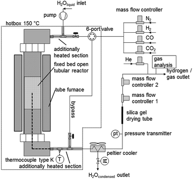 | ||
| Fig. 2 Schematic process diagram of the experimental test rig for high pressure hydrogen production out of a synthesis gas mixture. | ||
Reduction reactions were performed at 1023 K using a gas mixture of H2, CO, CO2 (He was added as an external standard). The reductions were performed for 90 respectively 210 minutes. Each reduction was concluded by a nitrogen purge step with 150 ml min−1 for 30 minutes respectively several hours including a cooling down phase. Each reduction was followed by an oxidation at elevated pressure (or at ambient pressure as reference) by introducing 0.06 g min−1 of water for approximately 60 minutes with a HPLC pump. The water was evaporated in the heated tubes before entering the reactor. Each cyclic experiment with a reduction length of 210 minutes was concluded by an air oxidation to completely remove solid carbon from the oxygen carrier.
b. Oxygen carrier samples
An oxygen carrier sample with a composition of 90 wt% Fe2O3, 5 wt% Al2O3 and 5 wt% CeO2 was prepared by a continuous co-precipitation based on the method of Kidambi et al.26 Particles with a grain diameter of 90–125 μm were calcinated at 1173 K for 3 hours. 7.00 g were used in the cyclic experiments. CeO2 was added to the oxygen carrier unlike to samples used in our previous work16,25 because of its positive effects on the activity and stability in a synthesis gas atmosphere.27Elemental analysis was performed after a microwave-assisted pressurised acid digestion by inductively coupled plasma atomic emission spectroscopy ICP-OES (Spectro Arcos SOP).
The surface of the oxygen carrier was analysed by scanning electron microscopy SEM (Zeiss Ultra 55, acceleration voltage 15 kV). Images of the fresh oxygen carrier and after the experimental test series were taken.
X-ray powder diffraction data were obtained on a Bruker AXS D8 Advance powder diffractometer in Bragg-Brentano geometry with LynxEye Detector, operated at 40 kV and 40 mA, using Cu Kα radiation (λ = 1.54178 Å). Diffraction angles were measured from 15–105° 2θ, having a step size of 0.025° 2θ, 5 s per step.
3. Results and discussion
a. Composition analysis of the fresh oxygen carrier sample
The elemental analysis results of the used sample and the calculated share of the metal oxides (under the assumption of completely oxidised state) are presented in Table 1.| Al wt% | Ce wt% | Fe wt% |
|---|---|---|
| 2.59 | 3.79 | 61.29 |
| Al2O3 wt% | CeO2 wt% | Fe2O3 wt% |
|---|---|---|
| 5.04 | 4.79 | 90.17 |
b. Reduction reactions with synthesis gas
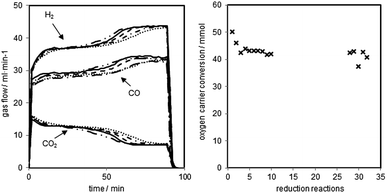
The reductions of the oxygen carrier were performed at 1023 K with a dry synthesis gas mixture of H2 54.5 vol%, CO 34.0 vol% and CO2 11.5 vol% and a total gas flow of 90 ml min−1. The reduction was executed for 90 minutes followed by a 30 minutes sweeping phase with nitrogen (150 ml min−1) and a steam-oxidation (0.06 g min−1 of water) at elevated pressure.The changes of gas flow characteristics with increasing cycle numbers are presented in Fig. 3 (left). Two noticeable reductions stages are visible within each cycle. Between minutes 20–40 the reduction of magnetite to wustite and between minutes 70–90 the reduction of wustite to iron take place.28–30 The two quasi stable stages are separated by a transition phase at around minute 60.
At the end, the reduction of wustite to iron is happening with a low conversion of the synthesis gases. The parallel occurring water gas shift reaction dominates and defines the outlet gas composition, which is in good accordance with equilibrium calculations from HSC Chemistry at this stage of the process.
The reductions were manually stopped after 90 minutes to guarantee reproducible conditions for each of the consecutive oxidations and to investigate the decrease of the oxygen carrier conversion. The shifting of the transition phases to an earlier reaction time (hydrogen flow from minute 60 to minute 50) indicates the degradation of the oxygen carrier and a loss of reactive surface.31 The reaction temperature of 1023 K leads to sintering of the solid, which reduces the porosity and the active volume of the pellets. Consequently, less magnetite is able to react with the synthesis gas.31 Another explanation for the degradation of the contact mass is the formation and accumulation of FeAl2O4. Studies have reported that FeAl2O4 is formed in the presence of Al2O3 if the iron based oxygen carrier is reduced beyond Fe3O4, which lowers the hydrogen yield, thus leading to a decreased oxygen carrier conversion.26,32 The third possible explanation is the formation of carbon on the oxygen carrier, which is not fully removed by the steam oxidations. This leads to accumulation of carbon and plating of the iron surface.33,34 The oxygen carrier conversion (Fig. 3 right), which expresses the exchanged oxygen atoms within the solid, shows a strong drop within the first two reductions and a slow linear decrease afterwards. After the first 11 cycles, a different test series (discussed in 3.d.), which included longer reductions and full oxidations to hematite with oxygen were executed. The reductions performed after that (number 27 to 31) display a slightly higher conversion than expected following the linear decrease within the first reduction set. This indicates a regeneration effect of the oxygen carrier by the complete air oxidations. This effect has also been reported by previous studies.16,35
c. Pressurised oxidations – hydrogen purity
After each reduction an oxidation at elevated pressure (oxidation at ambient pressure as reference) was performed. The hydrogen flow was measured with a thermal mass flow controller (MFC 2 in Fig. 2). The hydrogen purity was analysed with a gas chromatograph directly behind the system outlet. The two detected impurities were carbon monoxide and carbon dioxide. The hydrogen purity at different pressure levels (0–50 bar) and potential correlations were analysed. Fig. 4 shows the pressure profile and the gas flow adjustment of two representative pressurised oxidations.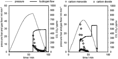 | ||
| Fig. 4 Representative pressure oxidations performed with 0.06 g min−1 of steam at 1023 K. Left corresponds to oxidation 2, right corresponds to oxidation 5 in Table 2. | ||
The oxidation starts with the pressure build-up by pumping water into the system. At this stage the system outlet is completely closed by the MFC 1. This leads to a linear pressure rise in the system. The steam oxidises the oxygen carrier in the reactor at a temperature of 1023 K by releasing hydrogen. At higher pressure levels the pressure rise slowly decreases, due to the oxygen carrier reaching the fully oxidised state. Unreacted steam is condensed at the system outlet in the peltier-cooler. After the system has reached the predefined pressure the MFC 1 is opened. The amount of produced hydrogen is analysed by the gas flow measured with the MFC 2.
The hydrogen purity measured at the different pressure levels and the amount of carbon monoxide and carbon dioxide are presented in Table 2. The hydrogen purity was within the range of 99.958–99.999% with a total amount of carbon monoxide in the range of 10–245 ppmv.35 The carbon monoxide characteristic of each oxidation shows a strong peak in the first part of the hydrogen flow measurement of several hundred ppmv and a decrease within 20 minutes below the detection limit of the gas chromatograph (approximately 20 ppmv). The highest initial CO concentration measured was 1633 ppmv (oxidation 4), the lowest 176 ppmv (oxidation 3). The experimental results clearly indicate that the carbon monoxide is immediately produced at the beginning of the oxidation with steam reaching the reactor and cracking solid carbon structures36 following eqn (7). This behaviour was also reported by C. R. Müller et al. during the steam oxidation in a fixed bed reactor under ambient pressure and similar experimental setup. They used a CO/CO2 gas mixture produced by coal gasification for the reduction of the oxygen carrier and the capturing of CO2.29
| Reaction | Maximum pressure bar | H2 amount mmol | H2 purity% | CO2 ppm | CO ppm |
|---|---|---|---|---|---|
| 1 Oxidation | 50 | 45.9 | 99.992 | 7 | 68 |
| 2 Oxidation | 50 | 43.9 | 99.985 | 104 | 47 |
| 3 Oxidation | 41 | 41.6 | 99.997 | 20 | 10 |
| 4 Oxidation | 41 | 40.0 | 99.958 | 171 | 245 |
| 5 Oxidation | 35 | 42.2 | 99.991 | 19 | 70 |
| 6 Oxidation | 34 | 42.0 | 99.992 | 48 | 27 |
| 7 Oxidation | 26 | 41.8 | 99.994 | 8 | 48 |
| 8 Oxidation | 25 | 37.1 | 99.991 | 34 | 53 |
| 9 Oxidation | 17 | 40.2 | 99.976 | 107 | 132 |
| 10 Oxidation | 44 | 36.5 | 99.996 | 0 | 41 |
| 11 Oxidation | 40 | 44.9 | 99.995 | 5 | 43 |
| 16 Oxidation | 50 | 48.9 | 99.946 | 107 | 438 |
| 17 Oxidation | 40 | 49.8 | 99.962 | 79 | 305 |
| 18 Oxidation | 50 | 49.4 | 99.953 | 82 | 385 |
| 19 Oxidation | 32 | 47.6 | 99.941 | 107 | 487 |
| 20 Oxidation | 2 | 45.2 | 99.957 | 103 | 328 |
| 27 Oxidation | 30 | 39.2 | 99.999 | 48 | 181 |
| 28 Oxidation | 21 | 37.4 | 99.984 | 13 | 149 |
| 29 Oxidation | 3 | 36.2 | 99.980 | 42 | 162 |
| 30 Oxidation | 30 | 37.3 | 99.982 | 64 | 117 |
| 31 Oxidation | 2 | 36.0 | 99.987 | 18 | 112 |
The carbon dioxide concentration shows a similar behaviour to CO. At the first couple of minutes of the hydrogen flow measurement a higher CO2 concentration is detected, followed by a decrease, which is probably the result of the water gas shift reaction (WGS) (eqn (8)). The initial CO2 concentration is significantly lower than expected from thermodynamic calculations. A possible explanation is that the high amount of hydrogen, due to high conversion of steam in the presence of Fe, and the high reaction temperatures favour the left side of the WGS equilibrium, thus a high CO/CO2 ratio.16
| C(s) + H2O → CO + H2 | (7) |
| CO + H2O → CO2 + H2 | (8) |
The carbon dioxide concentrations contain an additional irregularity. Oxidations with higher concentrations and lower concentrations of CO2 are alternating in the test series (oxidations 1–11). An explanation for this is the duration of the sweeping phase between the reduction and oxidation with nitrogen. The oxidations (1, 3, 5, 7, 10 and 11) with a CO2 concentration below 20 ppmv were performed after a sweeping phase of several hours over night including a cooling down phase and a heating up phase of the test rig. The results suggest that a significant part of the carbon dioxide is entrapped inside the micro pores of the oxygen carrier particles. The extended purge phase with nitrogen and possibly structural changes in the oxidation carrier by the cooling down phase completely remove CO2 residues, thus decrease the overall CO2 concentration.
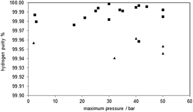
Analysing the hydrogen purity in Fig. 5, symbol ■, shows no correlation between the system pressure and the hydrogen purity. This is comprehensible because most of the carbon monoxide is produced in the initial stage of the oxidation where the pressure build up takes place and these conditions are similar in all cycles. This CO oxidation behaviour was also found in the experiments at ambient pressure (oxidations 29, 31), which were executed with a minor pressure build-up phase during the oxidation. Thus, the test clearly revealed that the steam-iron process is suitable to produce pressurised hydrogen out of reducing gas containing carbonaceous products. The increased system pressure shows no impact on purity of the produced hydrogen.
d. Experiments with increased carbon deposition
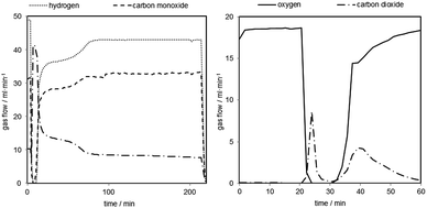
In order to further investigate the behaviour of carbonaceous contaminations at an increased system pressure, the reduction time was extended to precipitate a specific amount of solid carbon on the oxygen carrier. The reductions were performed for 210 minutes with the same reducing gas mixture as before followed by a 30 minutes sweeping phase with nitrogen (150 ml min−1). The carbon mass balance of the reductions reaction revealed the deposition of 4–10 mmol of solid carbon in each reduction. The consecutive oxidations with steam were performed at different pressure levels (50, 40, 30 bars and ambient pressure) under identical conditions as in the prior test series. Each steam oxidation was followed by an air oxidation at ambient pressure (100 ml min−1 for 45–60 minutes) to completely remove any solid carbon still left on the oxygen carrier and fully oxidize the oxygen carrier to hematite.A representative reduction is shown in Fig. 6 (left). The experiment starts with a full conversion of CO and H2 (minute 7) by the reduction of hematite to magnetite. Two additional steps are recognizable after that, which represent the magnetite to wustite and wustite to iron conversion.
Two representative oxidations are shown in Fig. 7 and the results of the oxidations are presented in Table 2 (oxidations 16–20). It is noteworthy that the first carbon monoxide peak is significantly higher but displays a similar shape to the prior test series. After an initial decrease the carbon monoxide concentration remains at a steady level of 40–50 ppmv. The initial CO concentration and the overall CO amount are about 5 to 10 times higher compared to the previous tests due to the longer reductions. The CO2 amount on the other hand is comparable to experiments with a shorter reduction time. The overall carbon monoxide content was in the range of 300 to 500 ppmv and the overall CO2 content between 80 and 110 ppmv, with a hydrogen purity between 99.94 and 99.96% (Table 2). The experiments revealed that only small amounts of the deposited carbon, approximately 5%, are re-oxidised with steam. Teixeira et al. reported a similar carbon oxidation behaviour. They suggest that at the beginning carbon structures are cracked until the iron can be oxidised by steam. The more stable graphitised carbon structures are then gradually oxidised. In their experiments the complete removal of carbon with steam was completed after 44 h.37 The remaining carbon after the steam oxidation serves as a substrate for new carbon deposition36 in the consecutive cycles, which eventually leads to accumulation of solid carbon and decreasing hydrogen purity with each cycling experiment unless an air-oxidation is performed in each cycle. This effect was not observed in the first set of experiments (1–11). A possible explanation is that the effect of accumulating carbon38,39 and its impact on the carbon monoxide amount were too subtle to be recognised in this test setup during the oxidation. The oxygen carrier conversion (Fig. 3 right) during the reduction reaction on the other hand might indicate some negative effect of solid carbon building up on the surface. It is possible that the slight decrease of oxygen carrier conversion from reduction 3 to 11 is related to carbon occupying the surface and blocking pores and thus inhibiting the reduction gases from reducing the oxygen carrier.34 Therefore, the complete air oxidations and the total removal of any solid carbon residue could explain the regeneration effect of the oxygen carrier conversion of cycles 27 to 31, mentioned in Section (3.b.).
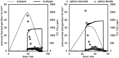 | ||
| Fig. 7 Two representative pressure oxidations performed with 0.06 g min−1 of steam at 1023 K. Left corresponds to oxidation 16, right corresponds to oxidation 19 in Table 2. | ||
The result of a representative air oxidation is shown in Fig. 6 (right). Three distinctive parts are noticeable. After the gas stream is switched from bypass to the reactor the oxygen flow immediately drops to 0 and a carbon dioxide peak becomes visible. This clearly indicates that solid carbon, which was not oxidised during the steam oxidation, is now removed from the oxygen carrier.35,40 The carbon dioxide flow decreases again (minute 27–32). At this point of the experiment it is likely that the reaction from magnetite to hematite exclusively takes place (eqn (6)). After minute 35 another carbon dioxide peak becomes visible, which indicates the oxidation of a different type or source of solid carbon deposition. The most likely explanation is that the first CO2 peak is the product of carbon oxidation located in the reactor inlet. At this part of the reactor the oxygen carrier was completely reduced to Fe, which is known for catalysing carbon deposition. This reaction takes place concurrently with the oxidation of magnetite to hematite. The second peak is measured after the breakthrough of the oxygen at the reactor. This indicates that the oxygen carrier conversion is completed and that another carbon deposit is located at the end of the fixed bed or in the inert section of the reactor outlet.
e. Post-experimental sample analysis with scanning electron microscopy and XRD diffraction analysis
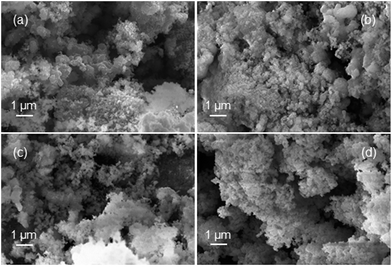
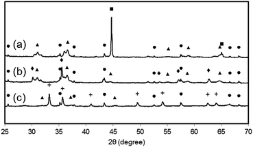
Samples of the fully reduced oxygen carrier (procedure described as in 3.4) were taken and analysed by scanning electron microscopy (Fig. 8) and X-ray powder diffraction analysis (Fig. 9) for further investigation. Image (8a) shows the fully reduced oxygen carrier. The sample displayed in image (8b) was re-oxidized with steam at ambient pressure in a thermogravimetric analysis system and sample (8c) was fully re-oxidized in a muffle furnace at ambient pressure in air. Image (8d) shows the fresh and fully oxidized oxygen carrier as a reference. The comparison of images (8a–c) with (8d) reveals that the oxygen carrier retained its porosity and structural integrity over the whole experiment of pressurized cycling. In all samples with different 3 oxidations stages small dense zones with less porosity are visible, which are related to thermal sintering and a source for the reduced oxygen carrier conversion.41Interestingly, samples (a) and (b) did not reveal any signs of solid carbon, although the analysis of the mass balance of the cyclic experiments strongly indicated that a significant amount of carbon is deposited during the reduction. Two possible explanations are conceivable. (i) The oxygen carrier is covered by the solid carbon in a thin layer, which cannot be detected by scanning electron microscopy. Other more noticeable forms of solid carbon, (filaments, plates, nanotubes) which are reported by other groups36,42 were not formed during the reduction reaction, thus not identified on any of the analysed samples. (ii) The carbon depositions occur not directly on the oxygen carrier but in its vicinity. Possible substrates for solid carbon are the reactor walls and the inert beds, which cover both reactor ends. The inevitable temperature gradient at both the reactor inlet and outlet can favour the formation of carbon deposits in these regions. This would lead to the measured carbon impurities in the hydrogen produced during the pressure oxidations.
The results of the X-ray powder diffraction analysis verify the absence of carbon in the oxygen carrier samples. Thus, under the described experimental conditions, the carbon formation does not take place on the oxygen carrier itself. This is also suggested by the experiment results obtained by the air oxidations and shown in Fig. 6 (right). Two detached CO2 peaks separated by a region of complete oxygen conversion, which corresponds to the oxidation of magnetite to hematite, were measured. This strongly indicates that two solid carbon sources are oxidised separately, which might be the reactor bed inlet and outlet.
It is noteworthy that the samples (a) and (b) revealed clearly visible peaks, which are related to hercynite FeAl2O4, implying a significant amount to be present in the sample. It can thus be concluded that the decrease in oxygen carrier conversion over the measured 11 cycles (Fig. 3 right) is a combination of thermal sintering effects and the accumulation of FeAl2O4.43 This unreactive structure is not removed by steam oxidations but the oxidation with air decomposes this component to Al2O3 and Fe2O3.32 Sample (c) shows almost the complete disappearance of peaks related to FeAl2O4, hence a regeneration of the oxygen carrier conversion is measured in the reductions 27 to 31.32
4. Conclusions
Cyclic reductions were performed using a Fe2O3/Al2O3/CeO2 oxygen carrier with synthesis gas mixture at 1023 K and ambient pressure. Steam oxidations were performed at different pressure levels up to 50 bar, which yielded 99.958–99.999% pure pressurised hydrogen. CO and CO2 were the identified contaminations, which were produced by the oxidation of solid carbon. Carbon depositions, which occurred during the reduction, were identified as the source for solid carbon. The pressurised oxidations showed that there is no correlation between the increased system pressure and the hydrogen purity. The experiments suggest that the solid carbon is not fully re-oxidised during the steam-oxidation and accumulating in the cyclic experiments. As a consequence the hydrogen purity is decreased gradually with each cycle unless an air oxidation step to completely remove the carbon residues is included.The post-experimental oxygen carrier analysis revealed that carbon deposition did not take place on the oxygen carrier itself but on both ends of the reactor. This is supported by the results of the air oxidations, which showed two CO2 peaks separated by a region of full oxygen conversion, which corresponds to the oxidation of magnetite to hematite.
The oxygen carrier conversion showed a slow linear decrease in the first set of cyclic experiments. A regeneration effect was achieved after steam oxidations including air oxidations were performed. Thermal stress, which leads to sintering and a reduced porosity of the oxygen carrier and the accumulated formation of FeAl2O4 reduce the hydrogen yield. Air oxidation can convert FeAl2O4 back to hematite and Al2O3, which explains the oxygen carrier regeneration.
The work has shown that chemical looping water splitting is suitable for the direct production of pressurised hydrogen using hydrocarbons as feed. The gas compression can be achieved in every fixed bed reactor, which complies with the requirements for high pressure. The main issue with hydrocarbons as feed is the formation of solid carbon and the subsequent hydrogen contamination. The results exhibited similar re-oxidation behaviour of solid carbon over the complete pressure range, hence whether the process is operated at atmospheric or elevated system pressure, the conditions to prevent the hydrogen impurities are identical.
Acknowledgements
The authors gratefully acknowledge support from NAWI Graz. This work is funded by the IEA-Research Cooperation on behalf of the Austrian Federal Ministry of Transport, Innovation and Technology. Supported by TU Graz Open Access Publishing Fund. The authors would like to thank the analytical staff of BIOENERGY 2020+ for their support with the elemental analysis of the oxygen carrier.Notes and references
- Climate Change 2013 The physical science basis, ipcc intergovernmental panel in climate change, http://www.climatechange2013.org/images/report/WG1AR5_ALL_FINAL.pdf, accessed February 26 2016 Search PubMed.
- Key World Energy Statistics 2014, IEA International Energy Agency, http://www.iea.org/publications/freepublications/publication/key-world-energy-statistics-2015.html, accessed February 26 2016 Search PubMed.
- N. Armaroli and V. Balzani, The hydrogen issue, ChemSusChem, 2011, 4, 21–36 CrossRef CAS PubMed.
- S. K. Ngoh and D. Njomo, An overview of hydrogen gas production from solar energy, Renewable Sustainable Energy Rev., 2012, 16, 6782–6792 CrossRef.
- W. C. Cho, D. Y. Lee, M. W. Seo, S. D. Kim, K. Kang, K. K. Bae, C. H. Kim, S. Jeong and C. S. Park, Continuous operation characteristics of chemical looping hydrogen production system, Appl. Energy, 2014, 113, 1667–1674 CrossRef CAS.
- J. D. Holladay, J. Hu, D. L. King and Y. Wang, An overview of hydrogen production technologies, Catal. Today, 2009, 139, 244–260 CrossRef CAS.
- B. Sørensen, Hydrogen and Fuel Cells Emerging Technologies and Applications, Academic Press, 2nd edn, 2011, pp. 5–94 Search PubMed.
- M. Singh, J. Moore, W. Shadis and P. Patterson,Hydrogen Demand, Production, and Cost by Region to 2050, Cent. for Transportation Res, Energy Syst. Division Argonne Natl. Lab. and TA Eng., Inc., 2005, http://www.transportation.anl.gov, accessed February 26 2016 Search PubMed.
- K. Zech, E. Grasemann, K. Oehmichen, I. Kiendl, R. Schmersahl, S. Rönsch, M. Seiffert, F. Müller-Langer, W. Weindorf, S. Funke, J. Michaelis and M. Wietschel, DBFZ Report Nr. 19, Hy-NOW, Evaluierung der Verfahren und Technologien für die Bereitstellung von Wasserstoff auf Basis von Biomasse, 2014, http://www.dbfz.de/web/fileadmin/user_upload/DBFZ_Reports/DBFZ_Report_19.pdf, accessed February 26 2016 Search PubMed.
- V. Hacker, G. Faleschini, H. Fuchs, R. Fankhauser, G. Simader, M. Ghaemi, B. Spreitza and K. Friedrich, Usage of biomass gas for fuel cells by the SIR process, J. Power Sources, 1998, 71, 226–230 CrossRef CAS.
- V. Hacker, A novel process for stationary hydrogen production: the reformer sponge iron cycle (RESC), J. Power Sources, 2003, 118, 311–314 CrossRef CAS.
- S. D. Fraser, M. Monsberger and V. Hacker, A thermodynamic analysis of the reformer sponge iron cycle, J. Power Sources, 2006, 161, 420–431 CrossRef CAS.
- M. Thaler and V. Hacker, Storage and separation of hydrogen with the metal steam process, Int. J. Hydrogen Energy, 2012, 37, 2800–2806 CrossRef CAS.
- D. D. Papadias, S. H. D. Lee, M. Ferrandon and S. Ahmed, An analytical and experimental investigation of high-pressure catalytic steam reforming of ethanol in a hydrogen selective membrane reactor, Int. J. Hydrogen Energy, 2010, 35, 2004–2017 CrossRef CAS.
- R. K. Ahluwalia, T. Q. Hua and J. Peng, Fuel cycle efficiencies of different automotive on-board hydrogen storage options, Int. J. Hydrogen Energy, 2007, 32, 3592–3602 CrossRef CAS.
- S. Nestl, G. Voitic, M. Lammer, B. Marius, J. Wagner and V. Hacker, The production of pure pressurised hydrogen by the reformer-steam iron process in a fixed bed reactor system, J. Power Sources, 2015, 280, 57–65 CrossRef CAS.
- M. Ortiz, L. F. Diego, A. Abad, F. García-Labiano, P. Gayán and J. Adánez, Hydrogen production by auto-thermal chemical-looping reforming in a pressurized fluidized bed reactor using Ni-based oxygen carriers, Int. J. Hydrogen Energy, 2010, 35, 151–160 CrossRef CAS.
- F. Garcia-Labiano, J. Adanez, L. F. Diego, P. Gayan and A. Abad, Effect of pressure on the behavior of copper-, iron-, and nickel-based oxygen carriers for chemical-looping combustion, Energy Fuels, 2006, 20, 26–33 CrossRef CAS.
- R. Xiao, Q. Song, M. Song, Z. Lu, S. Zhang and L. Shen, Pressurized chemical-looping combustion of coal with an iron ore-based oxygen carrier, Combust. Flame, 2010, 157, 1140–1153 CrossRef CAS.
- S. Zhang, C. Saha, Y. Yang, S. Bhattacharya and R. Xiao, Use of Fe2O3-Containing Industrial Wastes As the Oxygen Carrier for Chemical-Looping Combustion of Coal: Effects of Pressure and Cycles, Energy Fuels, 2011, 25, 4357–4366 CrossRef CAS.
- S. Zhang, R. Xiao and W. Zheng, Comparative study between fluidized-bed and fixed-bed operation modes in pressurized chemical looping combustion of coal, Appl. Energy, 2014, 130, 181–189 CrossRef CAS.
- O. Nordness, L. Han, Z. Zhou and G. M. Bollas, High-Pressure Chemical-Looping of Methane and Synthesis Gas with Ni and Cu Oxygen Carriers, Energy Fuels, 2016, 30, 504–514 CrossRef CAS.
- P. Hamers, Packed Bed Chemical-Looping Combustion experimental demonstration and energy analysis, PhD thesis, Eindhoven University of Technology, 2014.
- H. P. Hamers, F. Gallucci, G. Williams, P. D. Cobden and M. V. S. Annaland, Reactivity of Oxygen Carriers for Chemical-Looping Combustion in Packed Bed Reactors under Pressurized Conditions, Energy Fuels, 2015, 29, 2656–2663 CrossRef CAS.
- G. Voitic, S. Nestl, M. Lammer, J. Wagner and V. Hacker, Pressurized hydrogen production by fixed-bed chemical looping, Appl. Energy, 2015, 157, 399–401 CrossRef CAS.
- P. R. Kidambi, J. P. E. Cleeton, S. A. Scott, J. S. Dennis and C. D. Bohn, Interaction of Iron Oxide with Alumina in a Composite Oxygen Carrier during the Production of Hydrogen by Chemical Looping, Energy Fuels, 2012, 26, 603–617 CrossRef CAS.
- V. V. Galvita, H. Poelman, V. Bliznuk, C. Detavernier and G. B. Marin, CeO2-Modified Fe2O3 for CO2 Utilization via Chemical Looping, Ind. Eng. Chem. Res., 2013, 52, 8416–8426 CrossRef CAS.
- W. Liu, J. Y. Lim, M. A. Saucedo, A. N. Hayhurst, S. A. Scott and J. S. Dennis, Kinetics of the reduction of wüstite by hydrogen and carbon monoxide for the chemical looping production of hydrogen, Chem. Eng. Sci., 2014, 120, 149–166 CrossRef CAS.
- C. R. R. Müller, C. D. D. Bohn, Q. Song, S. A. Scott and J. S. Dennis, The production of separate streams of pure hydrogen and carbon dioxide from coal via an iron-oxide redox cycle, Chem. Eng. J., 2011, 166, 1052–1060 CrossRef.
- V. J. Aston, B. W. Evanko and A. W. Weimer, Investigation of novel mixed metal ferrites for pure H2 and CO2 production using chemical looping, Int. J. Hydrogen Energy, 2013, 38, 9085–9096 CrossRef CAS.
- L. Fan, Chemical looping systems for fossil energy conversions, John Wiley & Sons, Inc., Hoboken, New Jersey, 2010 Search PubMed.
- W. Liu, M. Ismail, M. T. Dunstan, W. Hu, Z. Zhang, P. S. Fennell, S. A. Scott and J. S. Dennis, Inhibiting the interaction between FeO and Al2O3 during chemical looping production of hydrogen, RSC Adv., 2015, 5, 1759–1771 RSC.
- J. Plou, P. Durán, J. Herguido and J. A. Peña, Purified hydrogen from synthetic biogas by joint methane dry reforming and steam-iron process: Behaviour of metallic oxides and coke formation, Fuel, 2014, 118, 100–106 CrossRef CAS.
- C. Trevisanut, F. Bosselet, F. Cavani and J. M. M. Millet, A study of surface and structural changes of magnetite cycling material during chemical looping for hydrogen production from bio-ethanol, Catal. Sci. Technol., 2015, 5, 1280–1289 CAS.
- C. D. Bohn, C. R. Müller, J. P. Cleeton, A. N. Hayhurst, J. F. Davidson, S. A. Scott and J. S. Dennis, Production of Very Pure Hydrogen with Simultaneous Capture of Carbon Dioxide using the Redox Reactions of Iron Oxides in Packed Beds, Ind. Eng. Chem. Res., 2008, 47, 7623–7630 CrossRef CAS.
- J. Zhang, A. Schneider and G. Inden, Effect of gas composition on cementite decomposition and coke formation on iron, Corros. Sci., 2003, 45, 281–299 CrossRef.
- I. F. Teixeira, T. P. V. Medeiros, P. E. Freitas, M. G. Rosmaninho, J. D. Ardisson and R. M. Lago, Carbon deposition and oxidation using the waste red mud: a route to store, transport and use offshore gas lost in petroleum exploration, Fuel, 2014, 124, 7–13 CrossRef CAS.
- R. Campo, P. Durán, J. Plou, J. Herguido and J. A. Peña, Combined production and purification of hydrogen from methanol using steam iron process in fixed bed reactor, J. Power Sources, 2013, 242, 520–526 CrossRef CAS.
- C. Trevisanut, M. Mari, J.-M. Millet and F. Cavani, Chemical-loop reforming of ethanol over metal ferrites: an analysis of structural features affecting reactivity, Int. J. Hydrogen Energy, 2015, 40, 5264–5271 CrossRef CAS.
- O. Vozniuk, S. Agnoli, L. Artiglia, A. Vassoi, N. Tanchoux, F. Di Renzo, G. Granozzi and F. Cavani, Towards an improved process for hydrogen production: the chemical-loop reforming of ethanol, Green Chem., 2016, 18, 1038–1050 RSC.
- E. Lorente, J. A. Peña and J. Herguido, Cycle behaviour of iron ores in the steam-iron process, Int. J. Hydrogen Energy, 2011, 6, 1–8 Search PubMed.
- K. Svoboda, G. Slowinski, J. Rogut and D. Baxter, Thermodynamic possibilities and constraints for pure hydrogen production by iron based chemical looping process at lower temperatures, Energy Convers. Manage., 2007, 48, 3063–3073 CrossRef CAS.
- A. Murugan, A. Thursfield and I. S. Metcalfe, A chemical looping process for hydrogen production using iron-containing perovskites, Energy Environ. Sci., 2011, 4, 4639–4649 CAS.
| This journal is © The Royal Society of Chemistry 2016 |

