DOI:
10.1039/C6RA05969D
(Paper)
RSC Adv., 2016,
6, 45250-45258
Point defect interactions in iron lattice: a first-principles study
Received
7th March 2016
, Accepted 25th April 2016
First published on 26th April 2016
Abstract
The interaction of point defects (interstitial atoms and vacancy) in both BCC Fe and FCC Fe lattices were investigated by first-principles calculations. The goals were to find the equilibrium separation of two interstitial atoms in the iron lattice and to establish the maximum trapping capacity of a mono-vacancy in the iron lattice. Based on our study, the equilibrium separation values of C–C, B–B and C–B were about 5.31 Å in the BCC Fe lattice. In the FCC Fe lattice, the equilibrium separation of C–C, B–B and C–B was about 6.42 Å. A mono-vacancy is shown to be capable of steady trapping as many as 3 atoms to form VXn (X = C/B, n = 0, 1, 2, and 3) and VCB, VC2B and VCB2 complexes in the BCC Fe lattice. For the FCC Fe lattice, it is energetically favorable for a mono-vacancy to accommodate 2 C atoms, 3 B atoms, 2 C atoms and 1 B atoms, 1 C atoms and 2 B atoms, and 1 C atoms and 3 B atoms to form VC2, VB3, VC2B, VCB2 and VCB3 clusters, respectively. However, when four interstitial atoms are in the same plane and occupy the nearest interstitial sites around the vacancy, they can also form VC4, VB4, VC2B2 and VCB3 in the BCC Fe lattice and VB4 and VC2B2 in the FCC Fe lattice. Moreover, we also found that the trapping ability of a vacancy is stronger in BCC Fe than in FCC Fe. These results are in good agreement with the available calculations and experiments results.
1. Introduction
The interaction between point defects, such as interstitial, impurities substitutional solute atoms and vacancies, in metals, as well as metal-alloys, which can modify the microstructure and change the mechanical properties of materials, have attracted considerable scientific and technological attention and interest.1–7 Among the point defects, interstitial and vacancies are the most frequent in metals. In particular, interstitial trapping at the vacancies have attracted significant attention because (1) vacancies are easier to study than other defects but have profound influences on the material properties, (2) vacancies have many surprises and mysteries yet to be explored, and (3) the insight gained from vacancies can be applied to other defects as well. However, experimental data about the interactions between point defects are scarce and difficult to obtain. Therefore, an understanding of this mechanism has attracted much attention over the last decade, and a large number of studies have been devoted to these issues, using complementary techniques such as Density Functional Theory (DFT), Molecular Dynamics (MD), Kinetic Monte Carlo (KMC), Mean Field Rate Theory (MFRT) and Dislocation Dynamics (DD) calculations. Among them, first-principles calculations based on the density functional theory, which can provide information at the atomistic level, are thus the most appropriate method to investigate these fine interactions to understand the basic atomic phenomena involved.
To date, there have been many studies on the interaction between nonmetallic elements such as hydrogen (H), helium (He), carbon (C), nitrogen (N), oxygen (O) and vacancies in metals. According to the previous experiments and theoretical simulations, C impurities have been found to interact strongly with vacancy-type defects in some metals and metal-alloys such as iron (α-Fe).8–10 Earlier experiments showed that the C impurity atom can be strongly trapped by a mono-vacancy in α-Fe, wherein positron-lifetime measurements show asymmetric C-vacancy (C1V) pairs at room temperature.9 Recent first-principles calculations8,11 have shown that C2V complexes are energetically favorable compared to C1V pairs in α-Fe. Zhang et al. systemically investigated the interactions between extrinsic H, He, O and C atoms in HCP Be and their interactions with a vacancy using first-principles methods.12 They concluded that the presence of a vacancy reduces the solution enthalpy of O and C and both O–O and C–C pairs are attractive while H–H and He–He pairs show weak repulsion. Ohnuma et al. calculated the binding energy of the vacancy–solute element in body-centered cubic iron.13 They pointed out that V–C3 and V–N2 are the most stable complex in BCC iron. Kong et al. came to the conclusion that solute atoms with larger electronegativity bond more favorably to the vacancy.14 More specifically, according to Fernandez's investigation, hydrogen has the ability to facilitate vacancy formation in metals, known as superabundant vacancies (SAV), when such vacancies are formed at high concentrations.15–17
However, most of the study has concentrated mainly on the hydrogen (H), helium (He), carbon (C), nitrogen (N), oxygen (O) in BCC Fe and other metals. Little attention has been given to boron (B) and FCC Fe, partly because the presence of boron in Fe and Fe-based alloys is very small. On the other hand, even a small amount of boron interstitial impurity affects the properties of steels significantly.18 In addition, all previous study focused on the behaviors of a single species of H, C or N and those interactions with the intrinsic point defects in BCC or FCC Fe. The interactions of Foreign Interstitial Atoms (FIAs) carbon–boron and those with a vacancy (V) have not been well investigated. Gibala and Ulitchny investigated the internal friction of some C-containing austenitic alloys.19 They found that with the increasing cold work, quenching and electron irradiation, the relaxation strength of the C peak goes up. From their study, they pointed out that the motion of C–V complexes contributes to the peak significantly. Point defects in metals have an important effect in the nucleation, evolution and kinetics of larger defects, which will influence the macroscopic deformation and failure mechanisms observed in many types of metals.20,21 These will have a direct impact on the design and operation of a fusion reactor.22 Boron is a common additive and has a very important effect on the mechanical properties of the materials, for example, increase in the ductility,23 tensile strength,24,25 toughness and creep rupture strength.25 An experimental investigation on the effects of boron addition on the mechanical properties of a normalized 0.15 C–0.22 Si–1.25 Mn steel shows that the minor addition of boron can decrease its impact transition temperature.26 Chi et al. indicated that 10 ppm boron addition in 3 Cr–Mo–V steel may effectively suppress its temper embrittlement because of the boron segregation to grain boundaries.27 We can observe that interactions between point defects in metals are central to many materials problems of great importance and have given rise to great research value. Therefore, the discussions of the relevance of C/B-related complex defects to Fe rich materials properties, major complex or formation mechanism of complex carbide and boride are necessary from a microscopic viewpoint, which will be of interested and useful for people who work on similar fields. In this study, we employ first-principles calculations to investigate the interactions of carbon–boron (C–B) and carbon–boron–vacancy (C–B–V) in both BCC and FCC Fe. When relevant, comparisons are made between the configurations of C–B, C–B–V and those of a single C or B, C–V, B–V, C–C–V, B–B–V in BCC and FCC Fe.
This study is organized as follows. First, a short section is devoted to provide a brief calculation method and verification of the accuracy of our calculations. Furthermore, we present the existing knowledge, mostly obtained through the use of electronic structure calculations, regarding the interactions of FIAs (C and B) with mono-vacancies and their clusters. A discussion section attempts to draw a general image of the data presented in the previous sections, and the last section presents what we believe are the tracks for future research in this field.
2. Methodology
2.1. Computation methods
The present calculations are based on the density functional theory (DFT), as implemented in CASTEP code.28–31 In our calculations, the supercells that are composed of 3 × 3 × 3 Fe structures and contain 54 atoms for BCC Fe and 108 atoms for FCC Fe were used to investigate the interaction of the FIAs (C and B) with mono-vacancies, respectively. The interactions between ions and electrons are described by the ultrasoft pseudopotentials of Vanderbilt type.32 Exchange and correlation functions are taken in a form proposed by Perdew–Burke–Ernzerhof's generalized gradient approximation (GGA-PBESOL).33 Following a series of test calculations, a plane wave cutoff of 500 eV and a k-point grid density of 3 × 3 × 3 is employed.34 The convergence thresholds of geometry optimization are set to 5 × 10⁻⁶ eV per atom for the energy change, 0.01 eV Å−1 for the maximum force, 0.02 GPa for the maximum stress and 5 × 10⁻⁴ Å for the maximum displacement.
To investigate the intrinsic properties of point defects in Fe, the defect formation energy is calculated by35
| | |
Ef(X) = E(Fe + X) − E(Fe) − E(X)
| (1) |
where
E(Fe + X) is the total energy of the Fe supercell with the X (X = B or C) atom at the interstitial site,
E(Fe) is the total energy of the pure Fe system, and
E(X) is the energy of the B or C atom at the ground state configuration.
The formation energy of vacancies is calculated by36
| |
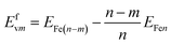 | (2) |
where
Efvm is the formation energy of
m vacancies,
EFe(n−m) and
EFen are the formation energies containing
n −
m and
n Fe atoms,
n = 54 and 108 for BCC and FCC Fe, respectively;
m = 1, 2… for the vacancies.
For a supercell containing n interacting entities (defects and impurities), (A1,…,An), the binding energy is calculated as follows:35
| |
 | (3) |
where
E(
Ai) is the energy of the supercell containing entity
Ai only,
E(
A1,…,
An) is the energy of the supercell containing all the entities, and
Eref is the energy of the perfect supercell.
The binding energy of the X atom to a single vacancy is calculated with the expression13
| | |
Eb(VXn) = nEint(X) + E(V) − E(V + nX) − nE(Fe)
| (4) |
where
Eint(X) is the energy of the system with an interstitial X atom,
E(V) is the energy of the system containing a vacancy (V), and
E(V +
nX) is the energy of the system with a VX
n cluster. According to the equation, a positive binding energy indicates attraction between these entities, whereas a negative value means repulsion.
2.2. Verification of the calculations
To verify the accuracy of our calculations, we first calculated the vacancy formation energies in BCC Fe. In Table 1, the calculated values were compared with the experimental data and the results of other calculations were obtained using first-principles and empirical methods.37–41 We can observe that our result for the vacancy formation energy is within the range of the scatter of the experimental data and slightly smaller than the results of the other calculations. As we know, the magnetic state may have some influence on the vacancy stability in a-Fe. Therefore, we take spin polarization into account and recalculate the monovacancy formation energy in a-Fe. The monovacancy formation energy is 1.91 eV, which is slightly smaller than 1.94 eV. The influence is little and can be ignored. Yang et al. investigated the He formation energies in BCC Fe and FCC Ni at the tetrahedral and octahedral sites with or without spin polarization.42 They found that the magnetism of the host atoms does not directly affect the relative stabilities of the He interstitial sites. In their early research about helium-defect interactions in alpha-iron, they also did not take spin polarization into account.43 We can conclude that DFT without spin polarization can be modeled to the behaviors of Fe with a vacancy.
Table 1 Formation energy of a single vacancy in BCC Fe
| Different methods |
Formation energy of a single vacancy (eV) |
| Ref. 37. Ref. 38. Ref. 39. Ref. 40. Ref. 41. |
| EAM (Johnson and Oh) |
1.73 |
| US-GGA (PW91, const. vol.)a |
2.09 |
| US-GGA (PW91, const. vol.)b |
2.02 |
| SIESTA-GGA (PBE, const. vol.)c |
2.07 |
| US-GGA (PAW-PBE)d |
2.17 |
| This work (PAW-PBESOL) |
1.94 |
| Experimental valuee |
2.0 ± 0.2 |
We find that the main difference between these calculations and other first-principles calculations is the cell relaxation. Other calculations were carried out under a constant-volume condition, whereas we relax the cell volume and cell shape. To verify the influence of cell relaxation, we calculate the single vacancy formation energy and the VC binding energy for different supercell sizes of 54, 128 and 250 atoms, as shown in Table 2. Brillouin zone integration was performed with a 5 × 5 × 5 mesh for the 54 atom supercell calculation and with a 3 × 3 × 3 mesh for the 128 and 250 atom supercell calculations. The vacancy formation energies converged rapidly to the supercell size for both the fully relaxed calculation and the constant-volume calculation. Both methods lead to similar satisfactory results for a small strain defect such as a vacancy. The vacancy formation energy (ref. 37) is slightly larger than the value obtained. This difference originates from the pseudopotential method. The ultrasoft pseudopotential (USPP) method overestimates the magnetic moment and magnetization energy, particularly for the GGA method.45 For the VC binding energy, the situation is different. The VC binding energy increases with increasing supercell size and converges at a supercell size of 128 atoms in the fully relaxed calculation, whereas it decreases with the supercell size and does not converge at a supercell size of 250 atoms in the constant-volume calculation. The VC binding energy obtained from the fully relaxed calculation is smaller than that obtained from the constant-volume calculation. The VC binding energy (ref. 44) is 0.11 eV smaller than the value we obtained. This is due to an overestimation of the magnetization energy by the USPP method. However, the PBESOL used in this study will still over-delocalize electrons in the Fe lattice. Paul Guss et al.46 discovered that the inclusion of a Hubbard U DFT correction,47,48 which is called DFT+U, was necessary for obtaining accurate quantitative agreement such as the band structures and band gaps. In our next study, we will try to employ DFT+U to undertake our calculations.
Table 2 Vacancy formation energy and VC binding energy
| Different supercells |
PAW full relax. |
PAW const. vol. |
USPP const. vol.a,b |
| V |
VC |
V |
VC |
V |
VC |
| Ref. 37. Ref. 44. |
| 54 atoms |
1.94 |
0.55 |
1.95 |
0.63 |
1.93 |
0.44 |
| 128 atom |
1.98 |
0.58 |
1.98 |
0.62 |
2.02 |
0.47 |
| 250 atom |
1.98 |
0.59 |
1.97 |
0.60 |
|
|
3. Results and discussions
3.1. Interactions between two interstitial atoms in iron
Carbon is one of the most commonly found impurities in iron. It can increase the hardness of iron, whereas boron is well known for its excellent ability to improve the hardenability of steels. They will generate strong interactions with the lattice defects available when these impurities are in the interstitial positions. The interactions between them have important effects on the yield stress and the subsequent mechanical properties of the materials. In previous study, including ours,35,49,50 we have noted that the octahedral (Oct) interstitial sites are the most stable position of C and B in BCC Fe, and in FCC Fe, the most stable site is also the octahedral sites. We now consider the different distances (see Fig. 1) of the interactions between two interstitial impurities in perfect Fe and select the most stable interstitial sites. In Tables 3 and 4, we summarized the binding energies at different distances of C–C, B–B and C–B pairs in BCC and FCC Fe. Our calculations are in good agreement with Domain's.38 We can observe that the binding energies between C–C, B–B and C–B are negative in both BCC and FCC Fe, which indicates that the interactions between them are repulsive. The repulsive force between them decreases with increasing distance. This implies that the carbon and boron atoms prefer to lie as far away from each other as possible. In BCC Fe, the equilibrium separations of C–C, B–B and C–B are about 5.31 Å. The C–C interactions are the most repulsive, C–B interactions are the least repulsive, and B–B interactions just lie between them. For FCC Fe, the repulsive interaction of B–B is stronger than C–B and C–C. As we can observe that the binding energies with every different distance are larger than C–B and C–C. However, the gap of the repulsive interaction among B–B, C–B and C–C become smaller and smaller, especially close to the equilibrium distances. The equilibrium separations of C–C, B–B and C–B are about 6.42 Å. We can observe clearly that the least stable configuration in BCC and FCC Fe is Cfg3 and Cfg2, respectively. This phenomenon may due to the special positions of the two interstitial atoms. They stay on top of each other and are aligned along the shortest and the most dilate direction of the interstitial site.
 |
| | Fig. 1 Possible configurations of two interstitial atoms close to each other: (a) B and C atoms in the BCC Fe lattice; (b) B and C atoms in the FCC Fe lattice. | |
Table 3 Summary of the binding energies (eV) with different distances (as shown in Fig. 1) between two impurities in BCC Fe
| Different configurations |
EC–C (eV) |
EC–B (eV) |
EB–B (eV) |
Different distances (Å) |
| Domain44 |
This work |
This work |
This work |
| Cfg1 |
−0.94 |
−0.98 |
−1.97 |
−1.87 |
2.01 |
| Cfg2 |
−0.42 |
−0.49 |
−1.76 |
−1.27 |
2.46 |
| Cfg3 |
−2.28 |
−3.15 |
−0.93 |
−1.14 |
2.84 |
| Cfg4 |
−0.17 |
−0.18 |
−0.72 |
−0.48 |
3.18 |
| Cfg5 |
−0.14 |
−0.12 |
−0.55 |
−0.36 |
4.02 |
| Cfg6 |
−0.20 |
−0.22 |
−0.23 |
−0.12 |
4.92 |
| Cfg7 |
|
−0.06 |
−0.08 |
−0.07 |
5.31 |
Table 4 Summary of the binding energies (eV) with different distances (as shown in Fig. 1) between two impurities in FCC Fe
| Different configurations |
EC–C (eV) |
EC–B (eV) |
EB–B (eV) |
Different distances (Å) |
| Cfg1 |
−0.72 |
−0.79 |
−0.86 |
2.43 |
| Cfg2 |
−1.19 |
−1.25 |
−1.36 |
3.43 |
| Cfg3 |
−0.39 |
−0.41 |
−0.46 |
4.20 |
| Cfg4 |
−0.22 |
−0.29 |
−0.35 |
4.85 |
| Cfg5 |
−0.13 |
−0.16 |
−0.29 |
5.42 |
| Cfg6 |
−0.08 |
−0.10 |
−0.15 |
5.94 |
| Cfg7 |
−0.01 |
−0.02 |
−0.03 |
6.42 |
3.2. Interactions of C and B with mono-vacancy
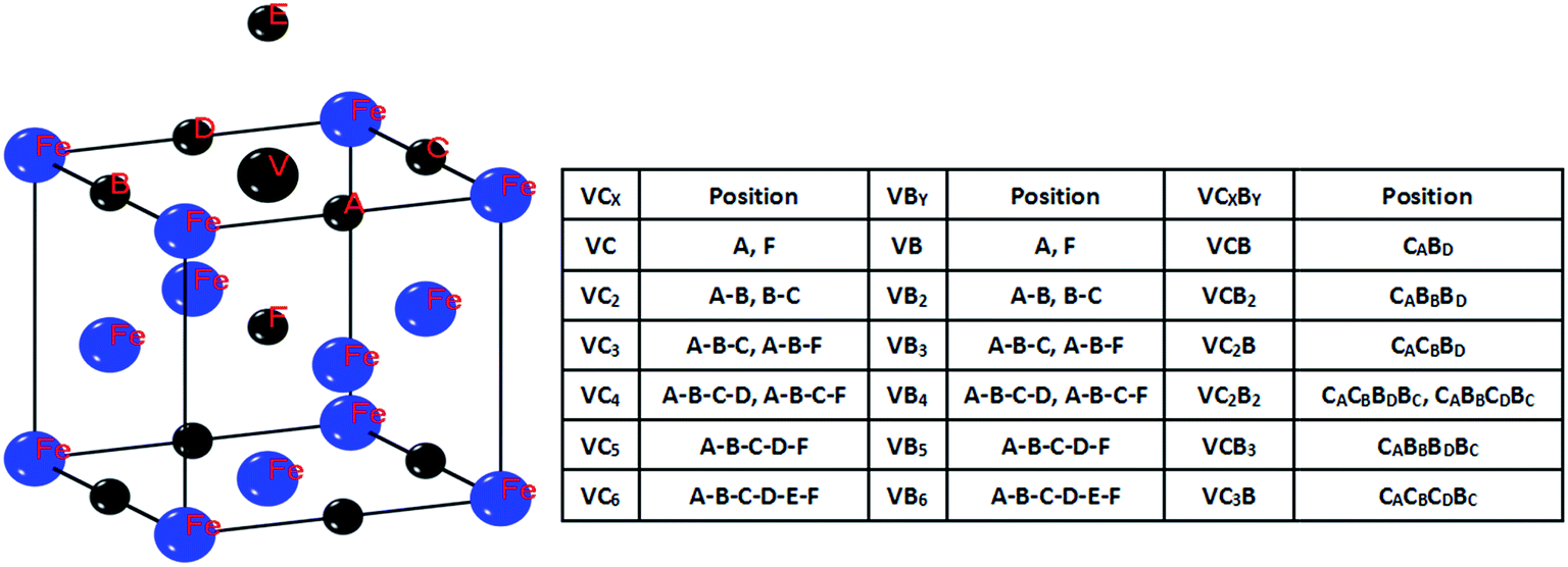
A mono-vacancy can accommodate multiple interstitial atoms by forming various clusters. In this section, we investigated the total binding energies of VCx, VBx and VCxBy in different topological configurations in both FCC and BCC Fe lattices. The most stable positions for the interstitial atoms around the mono-vacancy are considered. They are shown schematically in Fig. 2 and 3. The total binding energies are exhibited in Fig. 4 and 5. In a BCC Fe lattice, when a single boron atom is put near the vacancy, the boron atom will be trapped by the vacancy and take its site. It is as if the iron atom is replaced with a boron atom. The binding energy is 1.09 eV. This result is in good agreement with the experiments that the solution of boron is a substitutional type in the iron lattice.51–54 For a carbon atom, we also calculated the total binding energy of the VC complex with a carbon occupying the vacancy, but the value was negative (−0.75 eV). A carbon atom located at the octahedral site of the vacancy has a strong binding energy of 0.41–0.55 eV. This is consistent with the values of 0.41 eV and 0.48 eV obtained by the classical molecular dynamics studies of Johnson et al. and Rosato, respectively.55,56 When it comes to multiple atoms interacting with a vacancy, we can observe clearly that a vacancy can energetically bind up to 3 B atoms and 3 C atoms. The most stable cluster for carbon and boron is VC2 and VB2, because they have the largest binding energy. We also observed that when four boron atoms or four carbon atoms are in the same lattice plane with the vacancy, they also can form a VB4 and VC4 cluster. The total binding energies are negative for VC5 and VB5, as well as for some VC4 and VB4, so these configurations are clearly not stable. Possibly, the total binding energy is related to the configuration of the atoms. We also investigated the interaction between two types of interstitial atoms and a vacancy. The results showed that a vacancy can trap 1 C and 1 B, 1 C and 2 B, 2 C and 1 B to form the VCB, VC2B and VCB2 complexes. When the four interstitial atoms are in the same lattice plane with the vacancy, they also can bind together to form the VC2B2 and VCB3 complex. The stability of V–solute atom complex in FCC Fe lattice is different from BCC Fe lattice. For a single boron and carbon atom, the situation is the same with the BCC Fe lattice. A boron atom occupied the vacancy and formed a stable VB complex and had the binding energy of 0.76 eV. On the other hand, a carbon atom prefers to stay on the octahedral site of the vacancy and had a binding energy of 0.36–0.43 eV. This result is in good agreement with the value (0.36–0.41 eV) (ref. 57). We also calculated the binding energies of a mono-vacancy to multiple interstitial atoms. Both VC2 and VB3 obtain the positive values of 0.13–0.24 eV and 0.91–1.15 eV, respectively. This indicates that a mono-vacancy can securely trap at most 2 C atoms and 3 B atoms in a FCC Fe lattice. However, a vacancy also can trap 4 B atoms when they are on the same lattice plane. In the case of VCxBy, the VCB complex has the largest binding energy of 1.55 eV. VC2B, VCB2 and VCB3 also show a positive value of 0.49 eV, 0.66 eV and 0.42 eV, respectively. It is clear that when the atoms occupy the four octahedral interstitial sites surrounding the vacancy, they can also form a stable VC2B2 cluster. When we increase the number of carbon and boron atoms in the VCxBy complex, the total energy becomes negative. This indicates that a vacancy cannot trap more than 4 atoms in the FCC Fe lattice.
 |
| | Fig. 2 Definition possible configurations of VXmYn (m = 0, 1, 2, 3, 4; n = 0, 1, 2, 3, 4) complex structures in the BCC Fe lattice. | |
 |
| | Fig. 3 Definition possible configurations of VXmYn (m = 0, 1, 2, 3, 4; n = 0, 1, 2, 3, 4) complex structures in the FCC Fe lattice. | |
 |
| | Fig. 4 Total-binding-energy diagram of: (a) VCn complex, (b) VBn complex and (c) VCmBn complex in the BCC Fe lattice. | |
 |
| | Fig. 5 Total-binding-energy diagram of: (a) VCn complex, (b) VBn complex and (c) VCmBn complex in the FCC Fe lattice. | |
3.3. Electronic density difference map
To illustrate the results further, we also calculated the electronic density difference to analyze the interaction between the vacancy and the carbon and boron atoms. The electronic density difference maps are shown in Fig. 6 and 7. In the BCC Fe lattice, for an individual boron atom, we can observe from Fig. 6a that the boron atom substituted the vacancy to form a VB complex. When 2 B and 3 B atoms are located around the vacancy, they have a very strong electronic interaction among them. This implies that they can form a steady VB2 and VB3 complex. Fig. 6d shows that four boron atoms, which are in the same lattice plane, interact strongly with each other around the vacancy. The vacancy serves as a trapping center. For the carbon atoms, it can clearly be observed that a vacancy can trap 2 C, 3 C and 4 C atoms around it. When we add two types of atoms around the vacancy, the electronic interactions among them decreases with the increasing number of atoms. We can observe that the carbon and boron atoms not only interact with each other, but can also be attracted by the iron atoms nearby. When the interaction between the interstitial atoms and a vacancy is smaller than the interaction between the neighboring iron atoms and the interstitial atoms, the vacancy cannot trap the atoms to form a steady complex. Similar features of electronic interactions between solute atoms and a vacancy can be found in the FCC Fe lattice. The single boron atom replaced the vacancy and shows strong interactions with the neighboring iron atoms. A vacancy can also trap as many as four boron atoms. However, for the carbon atom, the solute–vacancy interaction becomes smaller and smaller with increasing number of carbon atoms. A vacancy can only trap two carbon atoms and the interaction between them is already relatively weak. The reason is clear from Fig. 7f and g that the carbon atoms interact strongly with neighboring iron atoms and cannot be trapped by the vacancy. For VCxBy complexes, we can observe from the figures that the interaction between boron atoms and the vacancy is stronger than the interaction between the carbon atoms and vacancy. Therefore, with increasing number of boron atoms, a mono-vacancy can form VCB2, VCB3 and VC2B2 complexes, while the VC2B and VC3B are not very stable. This is because the interaction of carbon-iron weakens the interaction between the vacancy and carbon atoms.
 |
| | Fig. 6 The differential charge density map for the atom-vacancy cluster in the (0 1 0) plane in the BCC Fe lattice. | |
 |
| | Fig. 7 The differential charge density map for the atom-vacancy cluster in the (0 1 0) plane in the FCC Fe lattice. | |
In BCC Fe, we can observe from Fig. 6b, e and h that the electronic density is different between the two FIAs (C–C, B–B and C–B). It is clear that the electronic density between B–B and C–B are higher than C–C. When there are three atoms around the vacancy, as shown in Fig. 6c, f, i and j, the electronic density among B atoms and C atoms are higher than C–C–B and B–B–C. In Fig. 6k and l, we can clearly observe that when two B atoms and two C atoms site around the vacancy, the electronic density is higher than VCB3 complex. We can observe a similar phenomenon in FCC Fe. However, compared to Fig. 6 and 7, the electronic density among B and C atoms are much smaller in FCC Fe, which indicate that the interactions among B, C and vacancy in FCC Fe are weaker than in BCC Fe. The bond type between C, B and Fe are very important. The electronic density difference maps can also provide some information about the bond type between C, B and Fe. We can observe from Fig. 6 and 7 that the electronic density are distributed evenly between C–C, B–B and C–B, which indicates the covalent character between C–C, B–B and C–B. However, the electronic density is an uneven distribution between C–Fe and B–Fe. It is clear that the electronic density is much closer to B and C atoms, so that the ionic character between Fe and interstitial is evident.
Overall, the electronic density difference maps further confirm the validity of the calculation of the binding energy.
4. Challenges and issues
The results presented above show the basic role played by first principles calculations in materials investigates today. Despite the limitations, it is still the most reliable method to study the interaction between solute atoms and vacancies and is very commonly used nowadays. However, we should also know that we need to pay more attention for obtaining meaningful data and introducing more precise potential functions, especially for the Fe–B potential functions.
As we know, DFT calculations are performed at 0 K. However, in real situations, we need to apply the models aiming at predicting the behavior, i.e., at room temperature at least. Another problem is that it is very hard for us to assess the clusters' behavior, for example, their stability, their diffusivity and their life time. In addition, although we have studied more than thirty different positions in our study, there are still many possible configurations that need to be investigated. It is a complicated study to find the most stable configuration of complexes. Finally, there are few experiment results available to compare with the calculation results. Most of the experiments were carried out 30 or 40 years ago. Thus, there is a direction to set up new experiments to study the interactions between point defects and solute atoms. In our point of view, the most promising method to make clear the interaction between point defects and solutes atoms is collaborating the involving experiments, theories and modelling.
5. Conclusions
The current advances in the study of solute atoms (including B and C) interaction, with each other and with a mono-vacancy in iron, have been investigated using the first-principles calculations. When two interstitial atoms (C–C/B–B/C–B) occupy their stability sites in the iron lattice, they will repel each other if they are too close. In this study, we obtained the equilibrium separation of C–C, B–B and C–B in both the BCC and FCC Fe lattices. The values are 5.31 Å for C–C, B–B and C–B in the BCC Fe lattice. In FCC Fe lattice, the equilibrium separation of C–C, B–B and C–B is about 6.42 Å. Our values are in good agreement with available calculation and experimental values. The interactions between mono-vacancy and multiple interstitial atoms in iron were also investigated. The mono-vacancy can act as a trapping center, which can drive large amount C/B atoms to gather towards the vacancy. For a single boron atom, no matter in BCC or FCC Fe lattice, when its location is close to the vacancy, it will replace the vacancy. We can observe this clearly from the electronic density difference map. This phenomenon is consistent with the fact that boron atoms prefer the substitution site in the iron lattice. For the trapping of multiple atoms in the vacancy, it can securely form VC2, VB2, VC3, VB4, VCB, VC2B, and VCB2 complexes in the BCC Fe lattice and VC2, VB2, VB3, VC2B, VCB2 and VCB3 complexes in the FCC Fe lattice. Among them, the VC2 and VB2 are the most stable clusters. This is consistent with other calculation results. However, when four interstitial atoms are in the same plane and occupy the nearest interstitial sites around the vacancy, they can also form VC4, VB4, VC2B2 and VCB3 in the BCC Fe lattice and VB4 and VC2B2 in the FCC Fe lattice. It is also clear that the trapping ability of a vacancy is stronger in BCC Fe than in FCC Fe. As we know, the trapping of atoms in the vacancies can lead to segregation in iron. Our study is important in directing further investigations about the formation mechanism of different complex carbide and boride in iron and steel. Our data for B can also be used to develop the Fe–B potential function, which is urgently needed.
Acknowledgements
We are thankful for the financial support from the National Natural Science Foundation of China (No. 51261013).
References
- D. Tanguy, Y. Wang and D. Connectable, Acta Mater., 2014, 78, 135–143 CrossRef CAS.
- T. Kresse, C. Borchers and R. Kirchheim, Scr. Mater., 2013, 69, 690–693 CrossRef CAS.
- D. Terentyev, K. Heinola, A. Bakaev and E. E. Zhurkin, Scr. Mater., 2014, 86, 9–12 CrossRef CAS.
- X. Xue, T. Wang, X. Jiang, C. Pan and Y. Wu, CrystEngComm, 2014, 16, 1207 RSC.
- G. Zhang, Y. Lu and X. Wang, Phys. Chem. Chem. Phys., 2014, 16, 17523 RSC.
- B. D. Malone, A. Gali and E. Kaxiras, Phys. Chem. Chem. Phys., 2014, 16, 26176 RSC.
- Y.-W. You, X.-S. Kong, X.-B. Wu, C. S. Liu, Q. F. Fang, J. L. Chen and G.-N. Luo, RSC Adv., 2015, 5, 23261 RSC.
- K. Tapasa, A. V. Barashev, D. J. Bacon and Y. N. Osetsky, Acta Mater., 2007, 55, 1 CrossRef CAS.
- A. Vehanen, P. Hautojarvi, J. Johansson, J. Ylikauppila and P. Moser, Phys. Rev. B: Condens. Matter Mater. Phys., 1982, 25, 762 CrossRef CAS.
- C. C. Fu, E. Meslin, A. Barbu, F. Willaime and V. Oison, Solid State Phenom., 2008, 139, 157 CrossRef CAS.
- C. Domain, C. S. Becquart and J. Foct, Phys. Rev. B: Condens. Matter Mater. Phys., 2004, 69, 144112 CrossRef.
- P. Zhang and J. Zhao, Comput. Mater. Sci., 2014, 90, 116–122 CrossRef CAS.
- T. Ohnuma, N. Soneda and M. Iwasawa, Acta Mater., 2009, 57, 5947–5955 CrossRef CAS.
- X.-S. Kong, X. Wu, Y.-W. You, C. S. Liu, Q. F. Fang, J.-L. Chen, G.-N. Luo and Z. Wang, Acta Mater., 2014, 66, 172–183 CrossRef CAS.
- N. Fernandez, Y. Ferro and D. Kato, Acta Mater., 2015, 94, 307–318 CrossRef CAS.
- M. Reith, et al., J. Nucl. Mater., 2013, 442, S173–S180 CrossRef.
- R. Nazarov, T. Hickel and J. Neugebauer, Phys. Rev. B: Condens. Matter Mater. Phys., 2010, 82, 224104 CrossRef.
- O. I. Velichko and N. V. Kniazhava, Comput. Mater. Sci., 2010, 48, 409–412 CrossRef CAS.
- M. G. Ulitchny and R. Gibala, Metall. Trans., 1973, 4, 497 CrossRef CAS.
- Y. Fukai and N. Okuma, Phys. Rev. Lett., 1994, 73, 1640 CrossRef CAS PubMed.
- K. Tapasa, A. V. Barashev, D. J. Bacon and Y. N. Osetsky, Acta Mater., 2007, 55, 1 CrossRef CAS.
- R. Causey, K. Wilson, T. Venhaus and W. R. Wampler, J. Nucl. Mater., 1999, 467, 266–269 Search PubMed.
- S. I. Bulat, N. A. Sorokina and E. A. Ulyanin, Met. Sci. Heat Treat., 1975, 17, 712 CrossRef.
- J. A. Jimenez, G. Gonzalez-Doncel and O. A. Ruano, Adv. Mater., 1995, 7, 130 CrossRef CAS.
- P. N. Ernst, P. J. Uggowitzer and M. O. Speidel, J. Mater. Sci. Lett., 1986, 5, 835 CrossRef CAS.
- M. I. Haq and N. Ikram, J. Mater. Sci., 1993, 28, 5981 CrossRef CAS.
- B.-H. Chi, T. Fujita, K. Shibata and F. Shimomura, J. Iron Steel Inst. Jpn., 1992, 78(5), 798 CAS.
- P. Hohenberg and W. Kohn, Phys. Rev. [Sect.] B, 1964, 136, 864–B871 CrossRef.
- W. Kohn and L. J. Sham, Phys. Rev. [Sect.] A, 1965, 140, 1133–1138 CrossRef.
- S. J. Clark, M. D. Segall, C. J. Pickard, P. J. Hasnip, M. I. J. Probert, K. Refson and M. C. Payne, Z. Kristallogr., 2005, 220, 567–570 CAS.
- M. D. Segall, J. D. L. Philip, M. J. Probert, C. J. Pickard, P. J. Hasnip, S. J. Clark and M. C. Payne, J. Phys.: Condens. Matter, 2002, 14, 2717 CrossRef CAS.
- D. Vanderbilt, Phys. Rev. B: Condens. Matter Mater. Phys., 1990, 41, 7892–7895 CrossRef.
- J. P. Perdew, et al., Phys. Rev. Lett., 2008, 100, 136406 CrossRef PubMed.
- H. J. Monkhorst and J. D. Pack, Phys. Rev. B: Solid State, 1976, 13, 5188–5192 CrossRef.
- Y. You, M. F. Yan and H. T. Chen, Comput. Mater. Sci., 2013, 67, 222–228 CrossRef CAS.
- D. Connetable, Y. Wang and D. Tanguy, J. Alloys Compd., 2013, 614, 222–228 Search PubMed.
- Y. Tateyama and T. Ohno, Phys. Rev. B: Condens. Matter Mater. Phys., 2003, 67, 174105 CrossRef.
- C. Domain and C. S. Becquart, Phys. Rev. B: Condens. Matter Mater. Phys., 2002, 65, 024103 CrossRef.
- C.-C. Fu and F. Willaime, Phys. Rev. Lett., 2004, 92, 175503 CrossRef PubMed.
- T. Ohnuma, N. Soneda and M. Iwasawa, Acta Mater., 2009, 57, 5947–5955 CrossRef CAS.
- L. De Schepper, D. Segers, M. Dorikens, G. Knuyt and L. Stals, et al., Phys. Rev. B: Condens. Matter Mater. Phys., 1983, 27, 5257 CrossRef CAS.
- Y. Li, Z. Xiaotao, W. Xiaoying, L. Kezhao and W. Zhiguo, J. Univ. Electron. Sci. Technol. China, 2008, 37(4), 558–560 Search PubMed.
- L. Yang, X. T. Zu, H. Y. Xiao, F. Gao, H. L. Heinisch, R. J. Kurtz and K. Z. Liu, Appl. Phys. Lett., 2006, 88, 091915 CrossRef.
- C. Domain, C. S. Becquart and J. Foct, Phys. Rev. B: Condens. Matter Mater. Phys., 2004, 69, 144112 CrossRef.
- G. Kresse and D. Joubert, Phys. Rev. B: Condens. Matter Mater. Phys., 1999, 59, 1758 CrossRef CAS.
- P. Guss, et al., J. Appl. Phys., 2014, 115, 034908 CrossRef.
- V. I. Anisimov, J. Zaanen and O. K. Andersen, Phys. Rev. B: Condens. Matter Mater. Phys., 1991, 44, 943–954 CrossRef CAS.
- V. I. Anisimov, F. Aryasetiawan and A. I. Lichtenstein, J. Phys.: Condens. Matter, 1997, 9, 767 CrossRef CAS.
- W. Wang, S. Zhang and X. He, Acta Metall. Mater., 1995, 4, 1693–1699 CrossRef.
- S. H. Zhang, Ph.D. thesis, University of Science & Technology, Beijing, 1992.
- F. Wever, Z. Anorg. Allg. Chem., 1930, 192, 317 CrossRef CAS.
- C. C. Mcbride, J. W. Spretnak and R. Speiser, Trans. Am. Soc. Met., 1954, 46, 499 Search PubMed.
- A. K. Shevelev, Dokl. Akad. Nauk SSSR, 1958, 123, 453 CAS.
- P. E. Busby and C. Wells, Trans. Metall. Soc. AIME, 1954, 200, 972 Search PubMed.
- R. A. Johnson, G. J. Dines and A. C. Damask, Acta Metall., 1964, 12, 1215 CrossRef CAS.
- V. Rosato, Acta Metall., 1989, 37, 2759 CrossRef CAS.
- J. A. Slane, C. Wolverton and R. Gibala, Mater. Sci. Eng., 2004, 370, 67–72 CrossRef.
|
| This journal is © The Royal Society of Chemistry 2016 |
Click here to see how this site uses Cookies. View our privacy policy here.