DOI:
10.1039/C6RA04897H
(Paper)
RSC Adv., 2016,
6, 58182-58187
CO2-in-PEG emulsion-templating synthesis of poly(acrylamide) with controllable porosity and their use as efficient catalyst supports†
Received
24th February 2016
, Accepted 10th June 2016
First published on 13th June 2016
Abstract
CO2-in-PEG emulsions were made with Pluronic 104 at different CO2 pressure. In these emulsions, porous poly(acrylamide)s (PAM) nanoparticles around 250 nm were prepared. The nano-sized metal Ru particles were loaded on the porous PAM, which have much higher catalytic activity for benzene hydrogenation reaction compared to commercial Ru/C catalyst. More importantly, the drop size of internal phase CO2 and the pore diameter of as-prepared PAMs can be simply tuned by changing the pressure of CO2.
1. Introduction
Porous polymers have attracted much attention owing to their diverse fascinating topologies, pore size tunability, and extensive usage in gas storage and separation,1–3 drugs release,4,5 catalysts,6–8 membranes,9 electrode materials,10 phase separation,11 etc. Several reliable methods, such as direct templating,12–15 block copolymer self-assembly,16–18 direct synthesis methodology19–21 and interfacial polymerization,22–24 could be used for preparation of porous polymers. Particularly, emulsion polymerization is an excellent method for preparation of porous polymers, and emulsion-templating techniques (high internal phase emulsion in-particular) are usually used to prepare porous polymers and other materials, wherein the internal phase (nonpolymerizable phase) usually act as a porogen,25–29 However, in some cases, both the internal phase and the continuous of emulsion might play a role as porogen that template porosity.30 Traditional oil-in-water (O/W) emulsions provide a direct template to a variety of porous hydrophilic polymers. The use of organic solvents suffers from economic and environmental costs and post-treatment complexity.
CO2 is cheap, non-toxic, and non-flammable. Compressed (liquid or supercritical) CO2 could be used to form emulsion as the internal phase.30,31 The properties of compressed CO2 can be tuned continuously by changing pressure and temperature.32 So far, some works on the formation of CO2 emulsions, include CO2-in-water emulsions and CO2-in-ILs emulsions have been reported.30,33,34 These emulsion systems have been used for preparation of porous polymers.
In the preparation processes, CO2 can be easily removed by reducing pressure and no contamination on the porous structure could happen. Besides compressed CO2, liquid poly(ethylene glycol)s (PEGs) are regarded as another green solvent. They are cheap, easily available, and have good solvation powers. More importantly, their properties are tunable by simply changing the molecular weight of PEG.35 Therefore, liquid PEGs have been used as solvent in various fields.36 To from microemulsions or emulsions of PEG and CO2 can expand the utility of these two green solvents. Recently, we have found that the PEG-in-CO2 microemulsion could be formed with the aid of surfactant N-EtFOSA (C2H5NHSO2C8F17).37 However, the emulsion consisted by PEG and CO2 has not been explored.
Herein, we prepared CO2-in-PEG emulsion used non-fluorous Pluronic 104 as surfactant. Porous poly(acrylamide) (PAM), which is widely used in stimuli responsive materials as polymer matrix38,39 and membrane science,40 was synthesized in the formed PEG emulsion under UV irradiation (λ = 254 nm) through a CO2-in-PEG emulsion templating route (Scheme 1). Furthermore, the PAM was used as a support to load Ru nanoparticle and Ru/PAM composites were synthesized under tip sonication. The as-synthesized Ru/PAM composites have high catalytic efficient for hydrogenation of benzene. The CO2-in-PEG emulsion could be used to replace the CO2-in-water emulsion in case the reactant is susceptive to water.
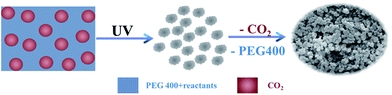 |
| | Scheme 1 Schematic illustration for the formation of porous polymers by a CO2-in-PEG emulsion templating route. | |
2. Experimental
2.1 Materials
The surfactant Pluronic 104 (P104, EO27PO61EO27) was obtained from BASF Corporation. The PEG-400 (poly(ethylene glycol)), N,N′-methylenebisacrylamide (laboratory grade), and benzophenone (97% purity) were purchased from Alfa Aesar. Acrylamide (AR) was produced by Beijing Chemical Reagent Company. Ruthenium(III) chloride hydrate (RuCl3·3H2O) was purchased from Shenyang Jinke Reagent Plant. Benzene (AR) was obtained from Beijing Chemical Reagent Company. Commercial Ru/C catalyst was purchased from Baoji Ruike Corporation, China. Double-distilled water was used. CO2 (>99.99% purity) and H2 (99.99% purity) were provided by Beijing Analytical Instrument Factory. PEG-400 was dried at 60 °C under vacuum for 48 h before use. All other materials were used directly without further purification.
2.2 Preparation of emulsions
The solution of surfactant in PEG was prepared by mixing P104 with PEG-400 together and the solution was transparent after dissolution. The apparatus for preparation of the emulsions consisted of a gas cylinder, a high-pressure sample cell with two quartz view windows and the cell volume was 9.5 mL, a high-pressure pump, a pressure gauge, and a YKKY A2 digital temperature controller. The apparatus and procedures were similar to those used previously.30 In a typical experiment, 0.48 g of P104 was added in 4.8 g PEG-400 at room temperature and stirred until they were totally miscible with the concentration of 9.1 wt%. Then, the solution was transferred into a steal cell, which is immersed in a water bath, with a constant temperature. After that, liquid CO2 was charged into the solution and stirred at desired pressure until the emulsion formed. At last the emulsions were stored at and the phase behavior at different pressure was observed.
2.3 Synthesis and characterization of PAM
9.1 wt% P104/PEG-400 (5.28 g) solutions were loaded in the view cell (9.5 mL). The monomer acrylamide (0.8 g), cross linker N,N′-methylenebisacrylamide (0.04 g) and initiator benzophenone (0.04 g) were added into the solution at 30 °C. CO2 was flowed into the cell with stirring until the desired pressure was reached. The two quartz view windows of the cell was radiated by two high-pressure mercury vapor lamps at wavelength of λ = 254 nm for 1 hour. Then CO2 was released slowly. The white product was washed with acetone for several times and dried at 60 °C under vacuum for 48 h.
The morphologies of PAMs were characterized by a HITACHI S-4800 scanning electron microscope and JEOL-1010 transmission electron microscope at 100 kV. The macroporosities were recorded by mercury intrusion porosimetry using a Micromeritics Autopore IV 9500 porosimeter. The samples were subjected to a pressure cycle starting at 5 psia, increasing to 44![[thin space (1/6-em)]](https://www.rsc.org/images/entities/char_2009.gif) 500 psia in predefined steps to give pore size/pore volume information. The porosity properties were determined by N2 adsorption/desorption isotherms using a Quadrasorb SI-MP system. FT-IR spectra were obtained by a Bruker Tensor 27 spectrometer. The TGA measurement was carried out on a TA Q50 with N2 flow of 40 mL min−1.
500 psia in predefined steps to give pore size/pore volume information. The porosity properties were determined by N2 adsorption/desorption isotherms using a Quadrasorb SI-MP system. FT-IR spectra were obtained by a Bruker Tensor 27 spectrometer. The TGA measurement was carried out on a TA Q50 with N2 flow of 40 mL min−1.
2.4 Synthesis of Ru/PAM composites
Typically, 0.05 g RuCl3·3H2O and 0.5 g PAM were initially dispersed in 50 mL of methanol solution to form a uniform suspension with the aid of tip sonication (Vibra Cell CVX, 500 W, 20 kHz) for 10 min. Then, 30 mL of a NaBF4 (1 g) methanol solution was added drop-wise into the dispersion containing metal precursor under tip sonication within 20 min. After the NaBF4 methanol solution was completely added, the mixture was continually subjected to tip sonication for 30 min. Finally, the obtained mixture was centrifuged, and the collected precipitate (Ru/PAM) was washed repeatedly with ethanol. Afterwards, the Ru/PAM catalyst was vacuum-dried at 60 °C for 12 h.
2.5 Hydrogenation of benzene catalyzed by Ru/PAM
The hydrogenation reaction was carried out in a stainless reactor of 15 mL. In a typical experiment, benzene (1.1 mL) and desired amounts of catalysts (benzene/Ru (mol/mol) = 5000) were added into the reactor. After being sealed, the reactor was put into a constant-temperature reacting furnace at a known temperature. H2 was then charged into the reactor until the desired pressure was reached, and the stirrer was started. After a desired reaction time, the excess H2 was released slowly. Then, the mixture was diluted by ethyl acetate. After that, the mixture was analyzed by gas chromatography (GC, Agilent 7890B), and identification of the products was done by GC-MS (Shimadzu QP2010).
3. Results and discussion
3.1 Formation of CO2-in-PEG emulsions
In the process for the formation of CO2-in-PEG emulsions, P104 was utilized as the surfactant to emulsify PEG-400 and CO2. It was found that the CO2-in-PEG emulsions were formed when the volume ratio of PEG to total volume of the cell (VPEG) was 0.6. The phase behaviors of the P104/PEG/CO2 systems were observed at 30 °C and 8.0 MPa, 10.0 MPa, 12.0 MPa and 14.0 MPa, respectively. The surfactant concentration with respect to the amount of PEG is 9.1 wt%. When the pressure of the CO2 is higher than 7.0 MPa, which is the saturated vapor pressure of CO2 at 30 °C, the CO2-in-PEG emulsions can be formed. Fig. 1 shows the photograph of the CO2-in-PEG before (a) and after phase separation (b) at 14.0 MPa. A system where a creaming front is formed (rising CO2 droplets) followed by the appearance of an upper clear phase (coalescence of CO2 droplets) is due to the creaming of dispersed CO2 droplets (CO2-in-PEG emulsion) rather than to the coalescence of dispersed PEG droplets (PEG-in-CO2 emulsion). The surfactant P104 favors the bottom PEG phase. It is identified as a CO2-in-PEG emulsions.41 After stopping the stirring, the system separated into two phases, an upper CO2-rich phase and a lower PEG-rich phase.
 |
| | Fig. 1 Photograph of the CO2-in-PEG emulsion before (a) and after phase separation (b) in 14.0 MPa. | |
3.2 Morphologies of PAMs
Fig. 2 shows the SEM and TEM images of the PAM synthesized within the emulsion at 14.0 MPa as an example. The macropores were about 200–500 nm. It is observed that the macropores were made of several particles, which is about 200 nm and dispersed uniformly. We also studied the properties of the polymer in the pressure of 8.0 MPa, 10.0 MPa and 12.0 MPa (Fig. S1†). As shown in Fig. S1,† it was found that the effect of the CO2 is more obvious at higher pressure. The particles of PAMs synthesized became more uniform with the increase of CO2 pressure. In addition, the particles of the polymer under different CO2 pressure were non-sticky. Furthermore, in order to prove the templating effect of the CO2-in-PEG emulsion, some control experiments were conducted. When the polymerization was conducted in PEG alone or the system of PEG and P104 in the absence of CO2, the synthesized PAM had no uniform shape and no obvious pores could be observed (Fig. S2†). These results indicated that the both the internal phase and continuous phase of CO2-in-PEG emulsion was the template for the growing of the polymers and the distribution of the particles could be tuned by the CO2 pressure. However, we can not exclude the possibility of P104 as porogen when CO2 is charged into the mixture.
 |
| | Fig. 2 SEM (a) and TEM (b) images of the PAM synthesized in CO2-in-PEG emulsion at 14.0 MPa. | |
3.3 Porosities of PAMs
The mercury porosimetry method was utilized to determine the macroposity of the as-synthesized PAM materials.30 Fig. 3 presents the macropore size distribution of the PAM at different pressure. It was found that the distribution of the macropores was wide. More importantly, Fig. 3 indicated that the pore size distribution of the PAM was narrowed and moved to the small pore diameter with the increase of the pressure, which is consistent with that observed from the SEM and TEM images (Fig. 2 and S1†). Furthermore, if the structure of the CO2-in-PEG emulsion could be retained during polymerization, i.e., CO2 was act as porogen, the degree of porosity of the PAM in as-formed emulsion could reach up to 40%, which is equal to the volume ratio of the internal phase. However, porosity degree (>69%) of the as-synthesized PAM formed in the emulsions at different CO2 pressure was higher than the volume fraction of CO2, which might be caused by the templating effect of the PEG-400 during polymerization.16 This is a proof that both the internal CO2 and the continuum phase PEG could play a role as porogen, which is similar to Peng and Zhang's report.30 The excess macropores with sizes in the hundreds of nanometers range as shown in Fig. 2 might originate from the release of the CO2 after polymerization. In addition, the effect of the CO2 was also more obvious on the distribution of the macropores (Fig. S1†) and the macropores were dispersed more uniformly along with the rising CO2 pressure. In addition, the synthesized PAM prepared in PEG alone or the system of PEG and P104 in the absence of CO2 showed no macropores, which was consistent with the results obtained from the SEM examinations (Fig. S2†), further indicating the templating role of both the internal phase and continuous phase of CO2-in-PEG emulsion. However, it should noted that again that P104 might act as porogen too in the emulsion. These results further indicated that the CO2-in-PEG emulsion was the template to induce the growing of the polymers.
 |
| | Fig. 3 Macropore size distribution of the PAM synthesized at 8.0 MPa, 10.0 MPa, 12.0 MPa, and 14.0 MPa. | |
The porosity properties of the PAM were also investigated by N2 adsorption–desorption method after the sample was degassed at 100 °C overnight (Fig. S3 and Table S1†). It was found that the mesopore size increased with the increasing CO2 pressure (Table S1†), which could be caused by the enlarged P104 micelles at higher pressures due to the templating effects of micelles on the mesopore formation.42 Meanwhile, the BET surface area and mesopore volume also increased with the increasing CO2 pressure (Table S1†). This could be resulted from that CO2 could be solubilized in bulk PEG-400 except for dissolving inside micelles and the amount of CO2 solubilized in the bulk phase increased with CO2 pressure, a phenomenon which had been reported for CO2-in-water micelles,43,44 and thus caused the PAM synthesized at higher pressure was more porous after releasing CO2. Therefore, the BET surface area and mesopore volume increased with the increasing of the CO2 pressure. In addition, the total macropore volume increased with CO2 pressure because of the increasing CO2 droplet size as the template of macropore (Table S1†). However, the increase in macropore volume was less than mesopore volume because the PEG-400 became more CO2 soluble at higher pressures.37 Therefore, the volume of mesopores compared to the volume of macropores changed with the CO2 pressure.
3.4 FT-IR spectra and TG of PAMs
The IR spectra of the PAMs synthesized in the emulsions and the pure acrylamide were also examined and the results were shown in Fig. 4. The acrylamide absorption peak of ![[double bond, length as m-dash]](https://www.rsc.org/images/entities/char_e001.gif) CH2 in 960 cm−1 was vanished in the spectrum of PAMs (curve a–d), confirming that monomers have polymerized completely.45 Meanwhile, in Fig. 4, there was a strong absorption at about 1663 cm−1, which could be attributed to the CO stretching in the –CONH2 group, and the shoulder around 1610 cm−1 was corresponding to the NH2 bending.45 TGA curves (Fig. 5) show that the polymer can stable at about 250 °C. In addition, it was also indicated that the PAMs synthesized in CO2-in-PEG emulsions at different pressures had similar stability.
CH2 in 960 cm−1 was vanished in the spectrum of PAMs (curve a–d), confirming that monomers have polymerized completely.45 Meanwhile, in Fig. 4, there was a strong absorption at about 1663 cm−1, which could be attributed to the CO stretching in the –CONH2 group, and the shoulder around 1610 cm−1 was corresponding to the NH2 bending.45 TGA curves (Fig. 5) show that the polymer can stable at about 250 °C. In addition, it was also indicated that the PAMs synthesized in CO2-in-PEG emulsions at different pressures had similar stability.
 |
| | Fig. 4 FT-IR spectra of PAMs synthesized in CO2-in-PEG emulsions at CO2 pressure of 8.0 MPa (a), 10.0 MPa (b), 12.0 MPa (c), 14.0 MPa (d) and the acrylamide monomer (e). | |
 |
| | Fig. 5 Thermogravimetric curves of the PAMs synthesized in CO2-in-PEG emulsions at different pressures. | |
3.5 Formation mechanism
The mechanism for the formation of macroporous PAM polymers in the as-formed CO2-in-PEG emulsion was presented in Scheme 1. At first, the reactants were dissolved in PEG phase. Then polymerization could occur stimulated by UV light, where the emulsion might act as template for the macropore formation. After the removal of CO2, PEG, and surfactant, a highly porous polymer could be formed (Scheme 1). Since more P104 can be dissolved in CO2 at higher pressure, the interface between the external phase PEG and internal phase CO2 is less curved, and furthermore the CO2 droplet size is increased. Therefore, the as-synthesized PAMs have larger macropores due to the templating effect of the CO2 internal phase at higher CO2 pressure.
3.6 Ru/PAM composite
As discussed above, the as-synthesized highly porous polymers had both macropores and mesopores. They have been used in catalysis as an efficient support. Herein, we utilized the as-prepared PAM as a support for a Ru catalyst. The Ru/PAM nanocomposites were prepared under tip sonication. The morphology of the Ru/PAM composites was examined by TEM. As shown in Fig. 6a, the PAM was loaded dispersedly with Ru nanoparticles with a mean diameter of about 2 nm. The high-resolution TEM (HR-TEM) examination (Fig. 6b) and the energy dispersive X-ray spectroscopy (EDS) analysis (Fig. 6c) confirm the existence of Ru element. The loading content of the Ru on PAM was 2.24 wt%, as determined by ICP-AES method.
 |
| | Fig. 6 TEM image (a), HR-TEM image (b) and EDS (c), of Ru/PAM particles obtained at CO2 pressure of 14.0 MPa. | |
The catalytic performance of the as-synthesized Ru/PAM for hydrogenation of benzene was examined using molecular H2 as the hydrogen resource under solvent-free conditions, and the results were presented in Table 1. Control experiments showed that the reaction could not happen without catalyst (Table 1, entry 1) or with PAM as the catalyst (Table 1, entry 2), indicating the catalytic effect of Ru nanoparticles. The catalytic activity was affected by the reaction temperature significantly from 30 °C to 60 °C with the same reaction time of 2.5 h (Fig. S4†). Benzene was almost completely converted into cyclohexane within 2.5 h at 60 °C and at H2 pressure of 6.0 MPa when using a substrate/Ru molar ratio of 5000 (Table 1, entry 5) and the turnover frequency (TOF) was about 2460 h−1. In contrast, the conversion of benzene was only 23% at 30 °C under the same reaction conditions with 60 °C with a TOF of 577 h−1. To our delight, the conversion of benzene could reach 93% with a TOF of 486 h−1 when the reaction time was prolonged to 12 h at 30 °C (Table 1, entry 6). In addition, it was found that the H2 pressure could also affect the reaction activity. When the H2 pressure was decreased from 6.0 MPa to 2.0 MPa with a reaction time of 2.5 h at 60 °C, the conversion of benzene decreased from >99–46% (Table 1, entry 8). Furthermore, the Ru/PAM could be reused at least four times without considerable decrease in the benzene conversion (Table 1, entries 5 and 8–11), indicating the catalyst was stable under the reaction conditions in our reaction system. For comparison, the benzene hydrogenation was performed using a commercial Ru/C catalyst under the same conditions (Table 1, entry 12). The TOFs of the Ru/PAM are much higher than commercial Ru/C catalyst. These results indicate that the as-synthesized Ru/PAM catalyst has a much higher activity.
Table 1 Catalytic activity test for the hydrogenation of benzenea
| Entry |
Catalyst |
PH2 |
Tb (°C) |
tb (h) |
Cc (%) |
TOFd |
| Reaction conditions: benzene 1.1 mL; benzene/Ru (mol mol−1) = 5000. T = temperature, t = time. Yield of cyclohexane by the hydrogenation of benzene. Turnover number (TON) = mol of product (cyclohexane) per mole of Ru, turnover frequency (TOF) = TON h−1. |
| 1 |
— |
6 |
60 |
2.5 |
0 |
— |
| 2 |
PAM |
6 |
60 |
2.5 |
0 |
— |
| 3 |
Ru/PAM |
6 |
60 |
1 h |
42 |
2634 |
| 4 |
Ru/PAM |
6 |
60 |
2 h |
96 |
2460 |
| 5 |
Ru/PAM |
6 |
60 |
2.5 h |
>99 |
>2483 |
| 6 |
Ru/PAM |
6 |
30 |
12 h |
93 |
486 |
| 7 |
Ru/PAM |
4 |
60 |
2.5 h |
72 |
2258 |
| 8 |
Ru/PAM |
2 |
60 |
2.5 h |
46 |
1154 |
| 9 |
Ru/PAM (2nd) |
6 |
60 |
2.5 h |
>99 |
>2483 |
| 10 |
Ru/PAM (3rd) |
6 |
60 |
2.5 h |
>99 |
>2483 |
| 11 |
Ru/PAM (4th) |
6 |
60 |
2.5 h |
>99 |
>2483 |
| 12 |
Ru/C |
6 |
60 |
7 h |
93 |
664 |
4. Conclusions
In this study, CO2-in-PEG emulsion was first formed by non-fluorous surfactant P-104. Then porous PAMs, which could be used as support for metal catalysts, were synthesized in the emulsion at different CO2 pressure. Furthermore, we synthesized the porous Ru/PAM nanocomposites, which were found to be high efficient for catalyzing hydrogenation of benzene. Moreover, the drop size of internal phase CO2 and the pore diameter of as-prepared PAMs can be simply tuned by changing the pressure of CO2. This work presents a novelty method for preparation of porous metal/polymer nanocomposites with highly dispersion, which could be used as catalysts in various catalytic reactions.
Acknowledgements
The authors thank for National Natural Science Foundation of China (21503016, 21473252) for financial support.
Notes and references
- C. H. Lau, K. Konstas, C. M. Doherty, S. Kanehashi, B. Ozcelik, S. E. Kentish, A. J. Hill and M. R. Hill, Chem. Mater., 2015, 27, 4756 CrossRef CAS.
- M. L. Foo, R. Matsuda and S. Kitagawa, Chem. Mater., 2014, 26, 310 CrossRef CAS.
- D. Yuan, W. Lu, D. Zhao and H.-C. Zhou, Adv. Mater., 2011, 23, 3723 CrossRef CAS PubMed.
- Y. Y. Li, F. Cunin, J. R. Link, T. Gao, R. E. Betts, S. H. Reiver, V. Chin, S. N. Bhatia and M. J. Sailor, Science, 2003, 299, 2045 CrossRef CAS PubMed.
- H. Zhang, D. Liu, M.-A. Shahbazi, E. Makila, B. Herranz-Blanco, J. Salonen, J. Hirvonen and H. A. Santos, Adv. Mater., 2014, 26, 4497 CrossRef CAS PubMed.
- Q. Sun, Z. Dai, X. Meng and F.-S. Xiao, Chem. Soc. Rev., 2015, 44, 6018 RSC.
- Q. Sun, Z. Dai, X. Meng, L. Wang and F.-S. Xiao, ACS Catal., 2015, 5, 4556 CrossRef CAS.
- L. Li, C. Zhou, H. Zhao and R. Wang, Nano Res., 2015, 8, 709 CrossRef CAS.
- R. Alink, J. Haussmann, H. Markoetter, M. Schwager, I. Manke and D. Gerteisen, J. Power Sources, 2013, 233, 358 CrossRef CAS.
- F. A. Amaral, R. M. Sousa, L. C. T. Morais, R. G. Rocha, I. O. Campos, W. S. Fagundes, C. N. P. Fonseca and S. C. Canobre, J. Appl. Electrochem., 2015, 45, 809 CrossRef CAS.
- S. A. Saba, M. P. S. Mousavi, P. Buehlmann and M. A. Hillmyer, J. Am. Chem. Soc., 2015, 137, 8896 CrossRef CAS PubMed.
- D. Wu, F. Xu, B. Sun, R. Fu, H. He and K. Matyjaszewski, Chem. Rev., 2012, 112, 3959 CrossRef CAS PubMed.
- S. Zhuo, J. Zhang, Y. Shi, Y. Huang and B. Zhang, Angew. Chem., Int. Ed., 2015, 54, 5693 CrossRef CAS PubMed.
- Q. Huang, J. Jiang, J. Chai, T. Yuan, H. Zhang, Z. Zou, X. Zhang and H. Yang, J. Power Sources, 2014, 262, 213 CrossRef CAS.
- C. Sun, J. Yang, X. Rui, W. Zhang, Q. Yan, P. Chen, F. Huo, W. Huang and X. Dong, J. Mater. Chem. A, 2015, 3, 8483 CAS.
- M. Seo, S. Kim, J. Oh, S.-J. Kim and M. A. Hillmyer, J. Am. Chem. Soc., 2015, 137, 600 CrossRef CAS PubMed.
- S. Dutta, A. Bhaumik and K. C. W. Wu, Energy Environ. Sci., 2014, 7, 3574 CAS.
- H. Sai, K. W. Tan, K. Hur, E. Asenath-Smith, R. Hovden, Y. Jiang, M. Riccio, D. A. Muller, V. Elser, L. A. Estroff, S. M. Gruner and U. Wiesner, Science, 2013, 341, 530 CrossRef CAS PubMed.
- Z. Yu, F. Tantakitti, T. Yu, L. C. Palmer, G. C. Schatz and S. I. Stupp, Science, 2016, 351, 497 CrossRef CAS PubMed.
- H. Zhong, C. Liu, Y. Wang, R. Wang and M. Hong, Chem. Sci., 2016, 7, 2188 RSC.
- L.-B. Sun, Y.-H. Kang, Y.-Q. Shi, Y. Jiang and X.-Q. Liu, ACS Sustainable Chem. Eng., 2015, 3, 3077 CrossRef CAS.
- K. Mathieu, C. Jerome and A. Debuigne, Macromolecules, 2015, 48, 6489 CrossRef CAS.
- Y. Liang, W. Mai, J. Huang, Z. Huang, R. Fu, M. Zhang, D. Wu and K. Matyjaszewski, Chem. Commun., 2016, 52, 2489 RSC.
- R. Dsouza, D. Sriramulu and S. Valiyaveettil, RSC Adv., 2016, 6, 24508 RSC.
- R. T. Woodward, D. W. H. Fam, D. B. Anthony, J. Hong, T. O. McDonald, C. Petit, M. S. P. Shaffer and A. Bismarck, Carbon, 2016, 101, 253 CrossRef CAS.
- W. Zhou, G. Tong, D. Wang, B. Zhu, Y. Ren, M. Butler, E. Pelan, D. Yan, X. Zhu and S. D. Stoyanov, Small, 2016, 12, 1797 CrossRef CAS PubMed.
- W. Yi, H. Wu, H. Wang and Q. Du, Langmuir, 2016, 32, 982 CrossRef CAS PubMed.
- S. Israel, I. Gurevitch and M. S. Silverstein, Polymer, 2015, 72, 453 CrossRef CAS.
- M. S. Silverstein, Polymer, 2014, 55, 304 CrossRef CAS.
- L. Peng, J. Zhang, J. Li, B. Han, Z. Xue and G. Yang, Angew. Chem., Int. Ed., 2013, 52, 1792 CrossRef CAS PubMed.
- R. Liu, C. Wu, Q. Wang, J. Ming, Y. Hao, Y. Yu and F. Zhao, Green Chem., 2009, 11, 979 RSC.
- P. G. Jessop, S. M. Mercer and D. J. Heldebrant, Energy Environ. Sci., 2012, 5, 7240 CAS.
- J. Zhang and B. Han, Acc. Chem. Res., 2013, 46, 425 CrossRef CAS PubMed.
- H. Yu, D. Xu and Q. Xu, Chem. Commun., 2015, 51, 13197 RSC.
- H. Zhao, T. Zhang, T. Yan and M. Cai, J. Org. Chem., 2015, 80, 8849 CrossRef CAS PubMed.
- J. L. Perry, K. G. Reuter, M. P. Kai, K. P. Herlihy, S. W. Jones, J. C. Luft, M. Napier, J. E. Bear and J. M. DeSimone, Nano Lett., 2012, 12, 5304 CrossRef CAS PubMed.
- Z. Xue, J. Zhang, L. Peng, J. Li, T. Mu, B. Han and G. Yang, Angew. Chem., Int. Ed., 2012, 51, 12325 CrossRef CAS PubMed.
- S. Hopkins, S. Carter, S. MacNeil and S. Rimmer, J. Mater. Chem., 2007, 17, 4022 RSC.
- Y. Tian, F. Su, W. Weber, V. Nandakumar, B. R. Shumway, Y. Jin, X. Zhou, M. R. Holl, R. H. Johnson and D. R. Meldrum, Biomaterials, 2010, 31, 7411 CrossRef CAS PubMed.
- T. Kurihara and A. Isogai, Cellulose, 2014, 21, 291 CrossRef CAS.
- E. Torino, E. Reverchon and K. P. Johnston, J. Colloid Interface Sci., 2010, 348, 469 CrossRef CAS PubMed.
- P. D. Yang, D. Y. Zhao, D. I. Margolese, B. F. Chmelka and G. D. Stucky, Nature, 1998, 396, 152 CrossRef CAS.
- J. L. Zhang, B. X. Han, Y. J. Zhao, J. S. Li and G. Y. Yang, Chem.–Eur. J., 2011, 17, 4266 CrossRef CAS PubMed.
- L. Peng, J. L. Zhang, S. L. Yang, B. X. Han, X. X. Sang, C. C. Liu and G. Y. Yang, Chem. Commun., 2014, 50, 11957 RSC.
- J.-F. Zhu, Y.-J. Zhu, M.-G. Ma, L.-X. Yang and L. Gao, J. Phys. Chem. C, 2007, 111, 3920 CAS.
Footnote |
| † Electronic supplementary information (ESI) available. See DOI: 10.1039/c6ra04897h |
|
| This journal is © The Royal Society of Chemistry 2016 |
Click here to see how this site uses Cookies. View our privacy policy here. 


