
In situ prepared V2O5/graphene hybrid as a superior cathode material for lithium-ion batteries
Srikanth Mateti,
Md Mokhlesur Rahman*,
Lu Hua Li,
Qiran Cai and
Ying Chen*
Institute for Frontier Materials, Deakin University, Waurn Ponds, VIC 3216, Australia. E-mail: m.rahman@deakin.edu.au; ian.chen@deakin.edu.au
First published on 24th March 2016
Abstract
Developing synthetic methods for graphene based cathode materials, with low cost and in an environmentally friendly way, is necessary for industrial production. Although the precursor of graphene is abundant on the earth, the most common precursor of graphene is graphene oxide (GO), and it needs many steps and reagents for transformation to graphite. The traditional approach for the synthesis of GO needs many chemicals, thus leading to a high cost for production and potentially great amounts of damage to the environment. In this study, we develop a simple wet ball-milling method to construct a V2O5/graphene hybrid structure in which nanometre-sized V2O5 particles/aggregates are well embedded and uniformly dispersed into the crumpled and flexible graphene sheets generated by in situ conversion of bulk graphite. The combination of V2O5 nanoparticles/aggregates and in situ graphene leads the hybrid to exhibit a markedly enhanced discharge capacity, excellent rate capability, and good cycling stability. This study suggests that nanostructured metal oxide electrodes integrated with graphene can address the poor cycling issues of electrode materials that suffer from low electronic and ionic conductivities. This simple wet ball-milling method can potentially be used to prepare various graphene based hybrid electrodes for large scale energy storage applications.
Introduction
Lithium-ion batteries (LIBs) power most portable electronic devices and are regarded as a potential power source for electric vehicles (EVs) and hybrid electric vehicles (HEVs). To meet the requirements for widespread use in EVs and HEVs, LIBs with satisfactorily high energy and power densities, safety, and cycling stability, must be developed.1 Therefore, there is an urgent need to develop high-performance electrode materials for next-generation LIBs. In LIBs, the cathode is typically a metal oxide and serves as the host for Li+-ion intercalation during the charge/discharge process. A variety of compounds have already been tested and some of them have been used commercially as cathode materials for the manufacture of lithium ion batteries.2 Among commonly used cathode materials, such as LiCoO2 (274 mA h g−1)3 and LiFePO4 (170 mA h−1),4 vanadium pentoxide (V2O5) has a theoretical capacity of 294 mA h g−1 when it is discharged to 2 V (vs. Li/Li+), which corresponds to two lithium intercalations.5 Additionally, it is attractive as a cathode material for LIBs because of its low cost, abundance, easy synthesis, and high energy density.6,7However, the practical application of V2O5 in LIBs is greatly limited by several issues:8–11 (i) low electronic conductivity, (ii) slow lithium-ion diffusion, and (iii) irreversible phase transitions upon deep discharge. As a consequence, V2O5 currently has very poor rate capabilities and very limited long-term cyclabilities. The rate capability of electrode materials is mainly determined by the kinetics of lithium-ion diffusion and electronic conductivity. Generally, the lithium-ion diffusion coefficient and the diffusion length are the two main factors that affect the rate of lithium-ion diffusion in the lattice of an electrode.12 It is well known that a decrease in diffusion distance can effectively shorten the diffusion time of lithium-ions within the electrode that is accompanied by nanomaterials during insertion/extraction, thus resulting in an enhanced rate capability.13–15 On the other hand, fast electron transport within the electrode also exerts a significant impact on the rate capability of LIBs. Electrode materials with low electronic conductivity produce resistance during cycling of the battery. As a result, the particle–particle interfaces became unfavourable for electron transportation, which leads to an unsatisfactory rate capability.2
To date, significant effort has been focused on improving the rate capability and cyclability of V2O5-based cathodes by overcoming intrinsic drawbacks of the materials. In particular, various nanostructured V2O5 (for example, nanoparticles, nanotubes, nanowires, nanorods, nanofibers, nano-belts, nano-rolls, nanosheets, porous microspheres, and porous microplates) have been synthesised to shorten the diffusion distance for Li+-ions and buffer the volume change during lithium intercalation and de-intercalation processes, as compared with bulk materials.9,10,16–25 Furthermore, these nanostructured V2O5 are integrated with carbon nanomaterials (such as surface carbon coating, carbon nanotubes, and graphene) to ensure better cyclability during long term charge/discharge by facilitating faster electron transfer within the electrode.26–29 These carbon nanomaterials not only enhance electrical conductivities of V2O5 electrode films, but also prevent agglomeration of nanostructured V2O5 active materials during cycling.
As a type of carbon material, graphene has attracted much attention in the field of LIBs. Graphene is a single-atomic layer of sp2-bonded carbon atoms arranged in a honeycomb crystal structure,30 which provides extraordinary electrical, mechanical, and thermal properties.31 Graphene can be prepared using either the chemical or thermal reduction of graphene oxide (GO),32 which is a layered stack of oxidized graphene sheets with different functional groups. However, a common problem in preparing nanostructured V2O5 based electrodes (such as nanostructured V2O5 and corresponding hybrids of V2O5/C, V2O5/CNTs, and V2O5/graphene) is that most of the production methods are drastically different from existing industrial processes, and these methods are difficult to scale up for large-quantity production.2,33–35
Herein, our comprehensive approach is to prepare V2O5/graphene hybrid electrodes via an in situ generation of graphene from graphite through the ball-milling technique where bulk graphite and V2O5 nanoparticles are used as starting materials. By employing a simple procedure of mechanical milling, bulk graphite is converted to a few layers of graphene in the presence of an argon atmosphere and at the same time, nanometre sized V2O5 particles, and its aggregates, are trapped and embedded among the crumpled graphene sheets. Therefore, such a novel structure is expected to provide intra-particle electronic conduction and lithium-ion diffusion simultaneously. Furthermore, the use of nanometre sized V2O5 particles, and particle aggregates, in particular, helps to overcome the issues of ionic conductivity (by reducing the length scales for ionic transport) and, to some extent, excessive stress developing in the electrode upon cycling. The hybrid we obtained exhibits markedly enhanced rate capabilities and excellent cyclabilities when used as a cathode material for LIBs. To prepare a few-layer graphene material from bulk graphite, mechanical ball-milling is not only an inexpensive alternative approach, but also a powerful approach for the in situ formation of metal oxide/graphene hybrids with enhanced electrochemical properties for LIBs electrodes.
Experimental
Preparation of V2O5 nanoparticles
To prepare V2O5 nanoparticles, commercial V2O5 (Sigma Aldrich, ≥98%) was used as a starting material. 4 g of commercial V2O5 and four hardened steel balls with a diameter of 25.4 mm each were loaded in a stainless steel milling container. The milling container was then evacuated and purged with argon gas 3 times, and finally filled with argon gas with a starting pressure of 310 kPa. A high energy ball in conjunction with an external magnet was used to mill commercial V2O5 powders at a rotation speed of 160 rpm for 110 h. The milled V2O5 powders were removed from the ball-milling container in the presence of an inert argon atmosphere. The sample was labelled V2O5-bm.In situ preparation of V2O5/graphene hybrid
V2O5-bm nanoparticles and crystalline graphite (particle size < 20 μm, Sigma Aldrich) powders were mixed in 2![[thin space (1/6-em)]](https://www.rsc.org/images/entities/char_2009.gif) :1 and 4:1 weight ratios. Both mixtures were loaded separately inside a stainless steel milling container together with four hardened steel balls (diameter of 25.4 mm) along with a suitable amount of acetone as solvent. Both mixtures were milled in a rolling ball-mill at a rotation speed of 75 rpm for 25 h at room temperature under an argon atmosphere of 100 kPa. Normally, bulk graphite is composed of numerous graphene flakes that are attached by van der Waals attraction between adjacent graphene flakes. The ideal case is that graphene can be peeled from the bulk graphite layer by layer if the van der Waals attraction is minimised.36 During ball-milling, a shear force is generated when balls are moving. This dominating shear force is exerted in the lateral direction to overcome the van der Waals attraction and promote relative motion between graphite layers, which leads to exfoliating graphite to graphene. On the other hand, the acetone solvent is used an exfoliating agent to enhance the intercalation and promote exfoliation.37 At the same time, the dominating shear force also insert V2O5 nanoparticles, and nanoparticle aggregates, into the graphene sheets to produce V2O5/graphene hybrid materials. The produced hybrids are denoted as V2O5/graphene (2:1) and V2O5/graphene (4:1), respectively. The overall preparation procedure is schematically presented in Fig. 1.
:1 and 4:1 weight ratios. Both mixtures were loaded separately inside a stainless steel milling container together with four hardened steel balls (diameter of 25.4 mm) along with a suitable amount of acetone as solvent. Both mixtures were milled in a rolling ball-mill at a rotation speed of 75 rpm for 25 h at room temperature under an argon atmosphere of 100 kPa. Normally, bulk graphite is composed of numerous graphene flakes that are attached by van der Waals attraction between adjacent graphene flakes. The ideal case is that graphene can be peeled from the bulk graphite layer by layer if the van der Waals attraction is minimised.36 During ball-milling, a shear force is generated when balls are moving. This dominating shear force is exerted in the lateral direction to overcome the van der Waals attraction and promote relative motion between graphite layers, which leads to exfoliating graphite to graphene. On the other hand, the acetone solvent is used an exfoliating agent to enhance the intercalation and promote exfoliation.37 At the same time, the dominating shear force also insert V2O5 nanoparticles, and nanoparticle aggregates, into the graphene sheets to produce V2O5/graphene hybrid materials. The produced hybrids are denoted as V2O5/graphene (2:1) and V2O5/graphene (4:1), respectively. The overall preparation procedure is schematically presented in Fig. 1.
 | ||
| Fig. 1 Schematic of the material preparation procedure. | ||
Material characterization
X-ray diffraction (XRD) data were collected from powder samples on a PANalytical X'Pert Powder instrument using CuKα radiation (1.54 Å) operated at 40 kV with 30 mA current. XRD data were recorded over a range of 10 to 70° with a step time and size of 150 s and 0.02, respectively. The X'Pert data collector software in combination with the Joint Committee on Powder Diffraction Standards (JCPDS) powder diffraction files were used to identify the phases present. Thermogravimetric analysis (TGA) was performed via a Q50 thermogravimetric analyser in air to determine the actual amount of carbon in the hybrid samples. Transmission electron microscopy (TEM) investigations were performed using a JEOL JEM 2100F instrument operated at 200 kV. Raman spectroscopy measurements were performed using a Renishaw in via micro-spectroscopic system. The laser used had a wavelength of 514 nm. The power was 0.5 mW to prevent laser damage to the material. A 20× lens was used in the test. Each spectrum was accumulated from two scans. To test the electrochemical performance, V2O5 and V2O5/graphene powder samples were mixed with acetylene carbon black (AB) and a binder, polyvinylidene fluoride (PVdF, Sigma-Aldrich), in a weight ratio of 80:10:10 in solvent N-methyl-2-pyrrolidone (NMP, Sigma-Aldrich, anhydrous, 99.5%). The as-prepared slurry was spread onto Al foil substrates, average loading of 1.0–1.5 mg, and these coated electrodes were dried in a vacuum oven at 100 °C for 12 h. The electrode was then pressed using a 25 mm diameter disc to enhance the contact between the Al foil and the active material. Subsequently, the electrodes were cut to 1 × 1 cm2 and CR 2032 coin-type cells were assembled in an Ar-filled glove box. Li foil was used as the counter/reference electrode and a microporous polyethylene film was used as a separator. The electrolyte was 1 M LiPF6 in a mixture of ethylene carbonate (EC), diethylene carbonate (DEC), and dimethyl carbonate (DMC) with a volume ratio of 1:1:1. The cells were galvanostatically discharged–charged in the range of 2.0 to 4.0 V at different current densities using a LAND battery testing system (Wuhan LAND Electronics Ltd., China). The temperature in the laboratory was maintained within a range of 20 to 25 °C during the tests. Cyclic voltammograms (CV) were recorded using a Solartron Analytical electrochemical workstation at a scan rate of 0.05 mV s−1. Electrochemical impedance spectroscopy was performed on the cells over the frequency range of 100 kHz to 0.01 Hz using an Ivium-n-stat computer-controlled electrochemical analyser (Ivium Technologies, Netherlands).
Results and discussion
XRD patterns of the commercial V2O5 sample (V2O5-cm) and three ball-milled samples: V2O5-bm, V2O5/graphene (2:1), and V2O5/graphene (4:1) are shown in Fig. 2(a). All the pronounced diffraction peaks for all samples can be indexed to an orthorhombic crystal system (JCPDS 04-007-6245, space group Pmmn, space group number 59) with lattice parameters of a = 3.5640 Å, b = 11.5120 Å, and c = 3.8300 Å. However, it is observed that the XRD peaks of the V2O5/graphene (4:1) sample are shifted to higher angles, which may be due to defects in crystals.38,39 The low content of carbon (graphene) in the V2O5/graphene (4:1) sample facilitates more friction and impact between V2O5 particles and steel balls during milling. On the other hand, the friction and impact are minimised in the V2O5/graphene (2:1) sample due the presence of large amounts of carbon (graphene). As a result, more defects in the crystals are expected in the low carbon (graphene) content sample. The average crystallite sizes of the four samples were calculated using the Debye–Scherrer equation where the Si standard (111) peak is used as the full-width half-maximum (FWHM) reference. The average crystallite sizes were found to be 55, 57, 76, and 92 nm for V2O5-cm, V2O5-bm, V2O5/graphene (4:1), and V2O5/graphene (2:1) samples, respectively.
 | ||
| Fig. 2 (a) XRD patterns of V2O5-cm, V2O5-bm, V2O5/graphene (2:1), and V2O5/graphene (4:1) samples; (b) TGA analysis of V2O5/graphene (2:1) and V2O5/graphene (4:1) samples. | ||
For quantifying the amount of carbon (graphene) in the hybrid samples, TGA analysis was carried out in air. The hybrid samples were heated from 100 to 950 °C at a rate of 5 °C min−1. As can be seen from Fig. 2(b), both hybrid samples start to lose weight slowly in air with increasing temperature, and maximum weight loss was found around 350–650 °C. According to Fig. 2(b), weight loss for the samples at 100–350 °C could be attributed to the loss of moisture and volatile organic compounds contained in the hybrids whereas maximum weight loss at around 350–650 °C corresponds to the amount of carbon (graphene). Therefore, the amount of carbon (graphene) in the hybrid samples can be estimated to be approximately 30 wt% for V2O5/graphene (2:1) and 18 wt% for V2O5/graphene (4:1), respectively.
The structure of each sample was visualised using TEM. Bright-field imaging of the V2O5-cm sample reveals the flake-like morphology (Fig. 3(a)). Dense agglomerates of V2O5 nanoparticles are observed in the ball-milled V2O5-bm sample (Fig. 3(b)). The corresponding selected area electron diffraction (SAED) pattern is also depicted in the inset of the Fig. 3(b). The SAED pattern consists of a single component of V2O5 with d spacings of approximately 0.345, 0.198, and 0.149 nm that can be referenced to the crystallographic directions of (110), (051), and (170), respectively. These results are consistent with the XRD patterns obtained for this sample, as shown in Fig. 2(a). Fig. 3(c–f) display TEM bright field images of hybrid V2O5/graphene (2:1) (Fig. 3(c and d)) and V2O5/graphene (4:1) (Fig. 3(e and f)) samples, respectively. The corresponding SAED patterns for both hybrids are depicted in the inset of the Fig. 3(c and e). TEM results clearly demonstrate the presence of wrinkles and folds in the images, which are characteristic features of graphene sheets (Fig. 3(d and f)). To further confirm the characteristic features of graphene, Raman spectroscopy measurements were conducted (Fig. 9). The island-like V2O5 nanoparticles/aggregates are dispersed on the surface of graphene sheets and encapsulated by few-layer graphene. Typically wrinkled graphene sheets form a network and cover the highly dispersed V2O5 nanoparticles/aggregates, which significantly increases conductivity and stabilizes the cathode structure of the hybrid systems (Fig. 3(d and f)). V2O5 nanoparticles/aggregates were not only found anchored to graphene networks, but also trapped by few-layer graphene, which can ensure that most particles could contribute to the charge/discharge process.
 | ||
| Fig. 3 TEM characterization: (a) a bright-field image of V2O5-cm and (b) bright-field image and SAED pattern of V2O5-bm. TEM images (c–f) of the hybrid samples: (c) a bright-field image with SAED pattern and (d) magnified image of the local area in (c) of the hybrid V2O5/graphene (2:1) sample. (e) A bright-field image with SAED pattern and (f) magnified image of the local area in (e) of the hybrid V2O5/graphene (4:1) sample. | ||
Cyclic voltammograms (CV) of the electrodes were measured at a scan rate of 0.05 mV s−1 in the potential range of 4.0 to 2.0 V (vs. Li/Li+) (Fig. 4). This potential window was chosen to avoid the formation of an irreversible ω-phase of LixV2O5 (2 < x < 3) that occurs at deep depths of discharge.5 In the CV curves, the cathodic and anodic peaks are ascribed to the lithium-ion intercalation and de-intercalation processes for the electrodes, respectively. Three dominant cathodic peaks at the potentials of around 3.4, 3.1, and 2.2 V were observed for all electrodes, which correspond to a series of phase transformations during lithium-ion intercalation into the V2O5 crystal with the formation of intercalation compounds of ε-Li0.5V2O5, δ-LiV2O5, and γ-Li2V2O5, respectively.40,41 The cathodic peaks located at around 3.4 and 3.1 V correspond to the intercalation of the first equivalent of Li+ ion in the following two steps,
| V2O5 + 0.5Li+ + 0.5e− = ε-Li0.5V2O5 | (1) |
| ε-Li0.5V2O5 + 0.5Li+ + 0.5e− = δ-LiV2O5 | (2) |
 | ||
| Fig. 4 Cyclic voltammograms measured at a scan rate of 0.05 mV s−1 in the potential range of 4.0–2.0 V: (a) V2O5-cm; (b) V2O5-bm; (c) hybrid V2O5/graphene (2:1); and (d) hybrid V2O5/graphene (4:1). | ||
The second equivalent of Li+ ion is inserted through one single step at around 2.2 V.
| δ-LiV2O5 + 1.0 Li+ + 1.0 e− = γ-Li2V2O5 | (3) |
During the anodic process, three anodic peaks observed at around 2.5, 3.2 and 3.4 V were ascribed to the de-intercalation process of the two Li+-ions and the corresponding reverse phase transformations from γ-Li2V2O5 to δ-LiV2O5, ε-Li0.5V2O5, and V2O5 respectively, associated with the V4+/V5+ redox couple.2,8 Apart from the main redox peaks, a pair of extra cathodic/anodic peaks at around 2.6/2.7 V was observed for V2O5-bm, V2O5/graphene (2:1), and V2O5/graphene (4:1) electrodes. However, the pair of extra cathodic/anodic peaks is very obvious for the V2O5/graphene (4:1) electrode (compare to V2O5-bm and V2O5/graphene (2:1) electrodes), and might be assignable to strong side reactions caused by more defects in the crystals of the V2O5/graphene (4:1) sample.42 Furthermore, three dominant cathodic peaks are missing in the 1st cycle for the V2O5-bm and hybrid electrodes that could correspond to the lower open circuit potential (OCP) of the cells during testing. After electrode activation via the 1st cycle, the close overlap of the 2nd, 3rd, 4th, and 5th cycles indicate very good reversibility of the V2O5-bm, V2O5/graphene (2:1), and V2O5/graphene (4:1) electrodes.
Fig. 5 shows the first 5 cycles of the discharge (Li intercalation) and charge (Li de-intercalation) curves of the electrodes in the potential window of 2.0 to 4.0 V at a current density of 0.5C. The shape of the discharge/charge curves of the three samples (V2O5-bm; hybrid V2O5/graphene (2:1); and hybrid V2O5/graphene (4:1)) are almost identical, where three main plateaus appear in each of the discharge and charge processes, corresponding to the electrochemical reactions among the transitional phases. The potential plateaus observed in the discharge/charge curves are consistent with the three dominant redox peaks in the CV curves. However, the shape of the discharge/charge curves for the V2O5-cm electrode is different from other electrodes and a potential polarization effect is significant in this electrode, which may be due to the low conductivity and larger particle sizes of the sample. It is also clearly seen that the 1st discharge capacity for both hybrid electrodes is lower than that of the subsequent discharge capacities. This indicates that the 1st Li intercalation in to the crystal is not as smooth as the subsequent Li intercalation because the open circuit potential (OCP) was dramatically reduced for hybrid electrodes at the beginning of testing. After the 1st discharge, the potential was increased significantly.
 | ||
| Fig. 5 Galvanostatic discharge/charge potential profiles of (a) V2O5-cm; (b) V2O5-bm; (c) hybrid V2O5/graphene (2:1); and (d) hybrid V2O5/graphene (4:1) electrodes at 0.5C. Rate for the 1st, 2nd, 3rd, 4th, and 5th cycles. | ||
Cycling stability, rate performance and corresponding discharge/charge potential profiles for the electrodes are depicted in Fig. 6. The incorporation of in situ graphene into V2O5 has an extraordinary effect on its electrochemical performance. Both hybrid electrodes exhibit good cycling stability with high discharge capacities of 185 mA h g−1 (569 W h kg−1) for V2O5/graphene (4:1) and 157 mA h g−1 (412 W h kg−1) for V2O5/graphene (2:1) at 1C after 100 cycles, respectively (Fig. 6(a)). The achieved capacities are almost 63% for the V2O5/graphene (4:1) electrode and 53% for the V2O5/graphene (4:1) electrode with respect to the theoretical capacity of 294 mA h g−1. It is important to note that graphene is not electrochemically active within the discharge–charge potential range of 2.0 to 4.0 V and that the capacities are calculated based only on the weight of V2O5 in the electrodes.43 The capacity retention for the hybrid electrodes is also commendable and it was approximately 64% for the V2O5/graphene (4:1) electrode and 73% for the V2O5/graphene (2:1) electrode with respect to the 2nd cycle discharge capacity. On the other hand, significant capacity fading is observed for both V2O5-cm and V2O5-bm electrodes. The introduction of graphene also has a huge impact on the rate performance, which is a major issue for the electrodes without graphene (V2O5-cm and V2O5-bm).44
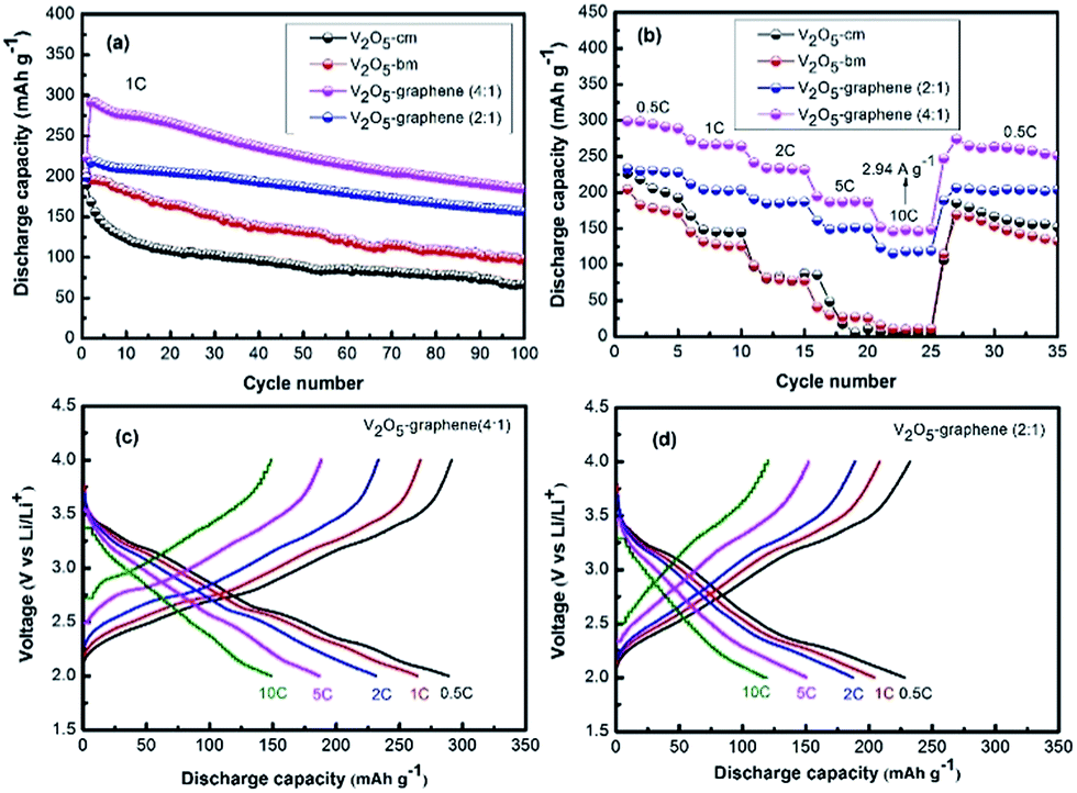 | ||
| Fig. 6 Electrochemical performances of the electrodes at 2 to 4 V: (a) cycling stability up to 100 cycles at a current rate of 1C (1C = 294 mA g−1); (b) rate capability at different current rates ranging from low to moderate to very high; (c and d) potential profiles of the 5th cycle obtained at different current rates. | ||
Fig. 6(b) demonstrates a consecutive cycling performance at different current rates, measured after 5 cycles in ascending steps from 0.5C to 10C, followed by a return to 0.5C. At higher current densities, both hybrid electrodes still retain a high capacity. Discharge capacities were measured to be 289 mA h g−1 (771 W h kg−1) at 0.5C, 264 mA h g−1 (706 W h kg−1) at 1C, 232 mA h g−1 (617 W h kg−1) at 2C, 187 mA h g−1 (495 W h kg−1) at 5C, and 149 mA h g−1 (390 W h kg−1) at 10C for the V2O5/graphene (4:1) electrode whereas it was 228 mA h g−1 (597 W h kg−1) at 0.5C, 204 mA h g−1 (534 W h kg−1) at 1C, 187 mA h g−1 (488 W h kg−1) at 2C, 150 mA h g−1 (387 W h kg−1) at 5C, and 120 mA h g−1 (303 W h kg−1) at 10C for the V2O5/graphene (2:1) electrode, respectively. As the rate returns to 0.5C, discharge capacities of both V2O5/graphene (4:1) and V2O5/graphene (2:1) electrodes are still 253 mA h g−1 (671 W h kg−1) and 203 mA h g−1 (559 W h kg−1) even after 35 cycles, respectively. After 35 cycles, the capacity recovery was calculated to be approximately 87% (in respect to capacity of 289 mA h g−1 obtained at the 5th cycle at 0.5C initially) and 89% (in respect to capacity of 228 mA h g−1 obtained at the 5th cycle at 0.5C initially) for V2O5/graphene (4:1) and V2O5/graphene (2:1) electrodes, respectively. However, the rate capability of the electrodes (without graphene) were observed to be significantly hampered at the 10C rate and their capacities faded rapidly to below 10 mA h g−1.
Fig. 6(c and d) further presents the potential profile of the first cycle for hybrid electrodes obtained at different current rates. Both hybrid electrodes still exhibited perfect discharge/charge characteristic shapes, which indicates that Li intercalation/de-intercalation is similar between different current rates. However, such a huge improvement on rate performance, particularly at high rates (10C), suggests that the in situ incorporation of graphene into V2O5 crystals not only tremendously increases electronic conductivity (both inter-particle and intra-particle conductivity) but also improves the ionic conductivities of the hybrid electrodes. It is interesting to note that the content of graphene in the hybrid electrode plays a critical role on their electrochemical performance. Clearly, the low content of graphene (V2O5/graphene (4:1) electrode) results in a higher discharge capacity at different current rates, while a high content of graphene (V2O5/graphene (2:1) electrode) leads to a lower discharge capacity, but much improved cycle stability (Fig. 6(a and b)). It is anticipated that the lower graphene content may result in a better dispersion of the graphene sheets among the V2O5 nanoparticles, while the higher graphene content may lead to restacking of the graphene sheets.45 It is also expected that thicker stacks of graphene could hold V2O5 nanoparticles/aggregates more tightly and, thus, maintain the structural integrity of the electrode during repeated cycling, consequently leading to a much better cycle life. Furthermore, higher graphene content may lead to more complete coverage over the V2O5 nanoparticles/aggregates, which could help to hold the V2O5 nanoparticles/aggregates together and prevent them from collapsing.33
To gain insight into the improved performance of the hybrid electrodes, and the structure–function relationship of the material, an EIS and ex situ TEM characterization tests were conducted. The cycling stability and rate capability of the hybrid V2O5/graphene (2:1) and V2O5/graphene (4:1) electrodes were significantly superior to the electrodes made from other samples of V2O5-cm and V2O5-bm. These improvements originate from the in situ generation of graphene. The role of this graphene host is quite obvious as it forms a conducting network, resulting in more efficient electronic and ion transport in the electrode. The electrochemical impedance spectra of the V2O5-cm, V2O5-bm, V2O5/graphene (2:1) and V2O5/graphene (4:1) electrodes are shown in Fig. 7. In the spectrum, the inclined lines in the lower frequency region correspond to the Li diffusion processes inside the electrode material and a semicircle in the medium-frequency region is related to the charge transfer resistance of the electrolyte and the electrode interface. The Nyquist plots in the medium frequency range clearly show that the diameters of the semicircles of hybrid electrodes are much smaller than that of the V2O5-cm and V2O5-bm electrodes, indicating that the hybrid electrodes provide much easier charge transfer at the electrode–electrolyte interface and, consequently, decrease the overall internal cell resistance. The incorporation of graphene into V2O5 by the ball-milling process significantly enhances the conductivity of the hybrid electrodes since the graphene provides conductive paths in the vicinity of the V2O5 particles and is considered a key factor in the rate capability and cycling stability improvements of the V2O5/graphene hybrid electrodes.
 | ||
| Fig. 7 Electrochemical impedance spectra of the V2O5-cm, V2O5-bm, V2O5/graphene (2:1) and V2O5/graphene (4:1) electrodes. | ||
Fig. 8 exhibits the post-cycling TEM and HRTEM investigations on the electrodes extracted after 100 cycles of galvanostatic discharge/charge at 1C. Fortunately, the morphology of both hybrids remains well-preserved after intercalation/de-intercalation. Compared with their original morphologies (Fig. 3(c–f)), the V2O5 nanoparticles and aggregates are still anchored to the wrinkled graphene sheets (Fig. 8(a and d)), demonstrating that the graphene networks effectively accommodate the volume variation during cycling and stabilize the whole electrode structure, which ensures electron and ion transport in the electrode simultaneously. The SAED patterns of the hybrid electrodes at charging to 4 V are shown in Fig. 8(b and e). The SAED patterns show a single component of V2O5 (de-intercalated product) with d spacings of 0.334, 0.204, and 0.121 nm for the V2O5/graphene (2:1) electrode, which match well with the crystallographic directions of (110), (051), and (033), respectively (Fig. 8(b)). In the case of the V2O5/graphene (4:1) electrode, it was 0.325, 0.196, and 0.117 nm, and match well with the crystallographic directions of (110), (051), and (172), respectively (Fig. 8(e)). Fig. 8(c and f) represent HRTEM images of the electrodes taken from the region of Fig. 8(a and d), respectively. The in situ generated graphenes are composed of few-layers graphene with a d spacing of approximately 0.35 nm, which is in good agreement with the crystallographic direction of (002). Crystallinity of these graphenes is well retained even after cycling up to 100 cycles, which represents the high quality of this graphene. This observation clearly demonstrates the stability and robustness of this novel structure, which is beneficial for self-expansion and self-shrinkage buffering, and is capable of accommodating structural strains and favour an enhanced cycling performance.
 | ||
| Fig. 8 TEM investigation of the electrodes cycling up to 100 cycles at a current rate of 1C: images (a–c) of the hybrid V2O5/graphene (2:1) electrode: (a) a bright field TEM image; (b) the corresponding SAED pattern; and (c) the HRTEM image. Images (d–f) of the hybrid V2O5/graphene (4:1) electrode: (d) a bright field TEM image; (e) the corresponding SAED pattern; and (f) the HRTEM image. | ||
To further confirm the characteristic features and quality of graphene, Raman spectroscopy analysis was carried out on the V2O5/graphene hybrid electrodes. Fig. 9(a and b) compares Raman spectroscopy between the original materials (without cycling) and the cycled electrodes. Both materials exhibit the G-mode at about 1573 cm−1, and it is due to the E2g mode. The G-band arises from the stretching of the C–C bond in graphitic materials, and is common to all sp2 carbon systems. Furthermore, both materials exhibit a strong peak in the 2500–2800 cm−1 range in the Raman spectra that is a characteristic feature of sp2 carbon materials. Combined with the G-band, this spectrum is a Raman signature of graphitic sp2 materials and is called 2D-band. 2D-band is a second-order two-phonon process and exhibits a strong frequency dependence on the excitation laser energy. The 2D-band can be used to determine the number of layers of graphene. This is mainly because in multi-layer graphene, the shape of the 2D-band is much different from that of single-layer graphene. As shown in Fig. 9(a and b), the 2D-band is not much more intense or sharper as compared to the 2D-band in single-layer graphene.46,47 Low intensity with a broader 2D-band is consistent with multi-layer graphene.
 | ||
| Fig. 9 Room-temperature Raman spectra of V2O5/graphene hybrid samples: (a) original materials (without cycling) and (b) cycled electrodes after charging/discharging up to 100 cycles at 1C. | ||
Overall, the V2O5/graphene hybrid electrode simultaneously demonstrates good cycling stability, an excellent rate capability, and a high discharge capacity. Several factors might have contributions towards the enhanced electrochemical performance of the V2O5/graphene hybrid electrode discussed herein.
(i) Although carbon materials cannot directly provide storage capacity for Li+ in the cathode, they can assist in improving the performance significantly. They are expected to improve the electrical conductivity and stability, and inhibit agglomeration of the cathode materials.48 In this context, graphene is advantageous compared to other carbonaceous materials. Therefore, in the hybrid electrodes, graphene not only prevents aggregation of the intermediate and active materials, but also provides good electrical contact with the particles, which could reduce the polarization of the electrode. It is interesting to note that few-layer graphene can still be observed even after cycling the electrode (Fig. 8), which suggests that the graphene stacks are quite stable and can stabilize the whole electrode structure during cycling.
(ii) The V2O5/graphene hybrid structure not only facilitates the kinetics for Li+-ion diffusion and electron transport by shortening the diffusion pathways to the nanoscale, but also allows the most freedom for a change in dimension during lithium intercalation/de-intercalation.
(iii) In this hybrid structure, graphene not only serves as a matrix for V2O5 nanoparticles, it also acts as a building block and establishes inimitable superstructures with interconnected networks, which is more helpful fast transportation of Li+. Therefore, the performance of electrode material is dramatically improved.
(iv) The combined effects of electronic conduction and Li+ diffusion significantly improve the electrochemical performance.
These advantages result in a stable, high discharge capacity, as well as an improved rate capability of the hybrid electrodes.
Conclusions
To prevent the long-standing issues of low intrinsic electronic conductivity, slow lithium-ion diffusion and irreversible phase transitions on deep discharge of a V2O5 electrode, a hybrid of nanostructured V2O5 with graphene is proposed as a cathode for lithium-ion batteries. Herein, a simple and low cost wet ball-milling method was used to create the V2O5/graphene hybrid structure by in situ mechanical peeling of bulk graphite and simultaneously disperse them among V2O5 nanoparticles/aggregates. The V2O5/graphene hybrid effectively leads to significant improvements in electronic conductivity, structural stability, and ion diffusion, which in turn, results in excellent electrochemical performance. Lower contents of graphene results in a higher discharge capacity (185 mA h g−1) at 1C rate, while higher contents of graphene leads to a lower discharge capacity (157 mA h g−1), but with much improved cycling stability. This hybrid structure was also demonstrated to prevent self-aggregation of active materials and fully utilize the advantages of the active materials.Acknowledgements
Financial support from Deakin University Higher Degree Research Scholarship and an Alfred Deakin Fellowship Award 2015 is acknowledged. Authors also acknowledge the support from Deakin Advanced Characterization Facility.Notes and references
- C. Zhang, Z. Chen, Z. Guo and X. W. Lou, Energy Environ. Sci., 2013, 6, 974 CAS.
- X. F. Zhang, K.-X. Wang, X. Wei and J.-S. Chen, Chem. Mater., 2011, 23, 5290 CrossRef CAS.
- R. Alcantara, P. Lavela, J. Tirado, R. Stoyanova and E. Zhecheva, J. Solid State Chem., 1997, 134, 265 CrossRef CAS.
- H. Huang, S.-C. Yin and L. S. Nazar, Electrochem. Solid-State Lett., 2001, 4, A170 CrossRef CAS.
- Y. Yang, L. Li, H. Fei, Z. Peng, G. Ruan and J. M. Tour, ACS Appl. Mater. Interfaces, 2014, 6, 9590 CAS.
- M. S. Whittingham, J. Electrochem. Soc., 1976, 123, 315 CrossRef CAS.
- D. Yu, C. Chen, S. Xie, Y. Liu, K. Park, X. Zhou, Q. Zhang, J. Li and G. Cao, Energy Environ. Sci., 2011, 4, 858 CAS.
- A. Pan, J.-G. Zhang, Z. Nie, G. Cao, B. W. Arey, G. Li, S.-q. Liang and J. Liu, J. Mater. Chem., 2010, 20, 9193 RSC.
- T. Zhai, H. Liu, H. Li, X. Fang, M. Liao, L. Li, H. Zhou, Y. Koide, Y. Bando and D. Golberg, Adv. Mater., 2010, 22, 2547 CrossRef CAS PubMed.
- A. M. Cao, J. S. Hu, H. P. Liang and L. J. Wan, Angew. Chem., Int. Ed., 2005, 44, 4391 CrossRef CAS PubMed.
- L. Mai, L. Xu, C. Han, X. Xu, Y. Luo, S. Zhao and Y. Zhao, Nano Lett., 2010, 10, 4750 CrossRef CAS PubMed.
- Y. Wang, H. Li, P. He, E. Hosono and H. Zhou, Nanoscale, 2010, 2, 1294 RSC.
- Y. Wang, Y. Wang, E. Hosono, K. Wang and H. Zhou, Angew. Chem., Int. Ed., 2008, 47, 7461 CrossRef CAS PubMed.
- X. L. Wu, L. Y. Jiang, F. F. Cao, Y. G. Guo and L. J. Wan, Adv. Mater., 2009, 21, 2710 CrossRef CAS.
- S. L. Chou, J. Z. Wang, J. Z. Sun, D. Wexler, M. Forsyth, H. K. Liu, D. R. MacFarlane and S.-X. Dou, Chem. Mater., 2008, 20, 7044 CrossRef CAS.
- Y. Wang, K. Takahashi, K. Lee and G. Cao, Adv. Funct. Mater., 2006, 16, 1133 CrossRef CAS.
- Y. S. Hu, X. Liu, J. O. Müller, R. Schlögl, J. Maier and D. S. Su, Angew. Chem., Int. Ed., 2009, 48, 210 CrossRef CAS PubMed.
- G. Li, C. Zhang, H. Peng and K. Chen, Macromol. Rapid Commun., 2009, 30, 1841 CrossRef CAS PubMed.
- Y. Wang, H. J. Zhang, W. X. Lim, J. Y. Lin and C. C. Wong, J. Mater. Chem., 2011, 21, 2362 RSC.
- B. Li, Y. Xu, G. Rong, M. Jing and Y. Xie, Nanotechnology, 2006, 17, 2560 CrossRef CAS PubMed.
- G. Li, C. Zhang, H. Peng and K. Chen, Macromol. Rapid Commun., 2009, 30, 1841 CrossRef CAS PubMed.
- A. M. Glushenkov, V. I. Stukachev, M. F. Hassan, G. G. Kuvshinov, H. K. Liu and Y. Chen, Cryst. Growth Des., 2008, 8, 3661 CAS.
- M. M. Rahman, A. Z. Sadek, I. Sultana, M. Srikanth, X. J. Dai, M. R. Field, D. G. McCulloch, S. B. Ponraj and Y. Chen, Nano Res., 2015, 8, 3591 CrossRef CAS.
- Q. An, P. Zhang, Q. Wei, L. He, F. Xiong, J. Sheng, Q. Wang and L. Mai, J. Mater. Chem. A, 2014, 2, 3297 CAS.
- X. Peng, X. Zhang, L. Wang, L. Hu, S. H. S. Cheng, C. Huang, B. Gao, F. Ma, K. Huo and P. K. Chu, Adv. Funct. Mater., 2016, 26, 784 CrossRef CAS.
- M. Sathiya, A. Prakash, K. Ramesha, J. M. Tarascon and A. Shukla, J. Am. Chem. Soc., 2011, 133, 16291 CrossRef CAS PubMed.
- H. Gwon, H.-S. Kim, K. U. Lee, D.-H. Seo, Y. C. Park, Y.-S. Lee, B. T. Ahn and K. Kang, Energy Environ. Sci., 2011, 4, 1277 CAS.
- H. Liu and W. Yang, Energy Environ. Sci., 2011, 4, 4000 CAS.
- M. Koltypin, V. Pol, A. Gedanken and D. Aurbach, J. Electrochem. Soc., 2007, 154, A605 CrossRef CAS.
- C. H. Lui, L. Liu, K. F. Mak, G. W. Flynn and T. F. Heinz, Nature, 2009, 462, 339 CrossRef CAS PubMed.
- M. J. Allen, V. C. Tung and R. B. Kaner, Chem. Rev., 2009, 110, 132 CrossRef PubMed.
- K. Zhao, L. Zhang, R. Xia, Y. Dong, W. Xu, C. Niu, L. He, M. Yan, L. Qu and L. Mai, Small, 2016, 12, 588 CrossRef CAS PubMed.
- Q. Liu, Z.-F. Li, Y. Liu, H. Zhang, Y. Ren, C.-J. Sun, W. Lu, Y. Zhou, L. Stanciu and E. A. Stach, Nat. Commun., 2015, 6, 1 Search PubMed.
- F. Carn, M. Morcrette, B. Desport and R. Backov, Solid State Sci., 2013, 17, 134 CrossRef CAS.
- X. H. Xia, D. L. Chao, Y. Q. Zhang, Z. X. Shen and H. J. Fan, Nano Today, 2014, 9, 785 CrossRef CAS.
- M. Yi and Z. Shen, J. Mater. Chem. A, 2015, 3, 11700 CAS.
- A. E. Del Rio-Castillo, C. Merino, E. Díez-Barra and E. Vázquez, Nano Res., 2014, 7, 963 CrossRef.
- P. Y. Liao, J. G. Duh, J. F. Lee and H. S. Sheu, Electrochim. Acta, 2007, 53, 1850 CrossRef CAS.
- G. Ali, J. H. Lee, S. H. Oh, B. W. Cho, K. W. Nam and K. Y. Chung, ACS Appl. Mater. Interfaces, 2016, 8, 6032 CAS.
- A. Odani, V. G. Pol, S. V. Pol, M. Koltypin, A. Gedanken and D. Aurbach, Adv. Mater., 2006, 18, 1431 CrossRef CAS.
- X. Rui, N. Ding, J. Liu, C. Li and C. Chen, Electrochim. Acta, 2010, 55, 2384 CrossRef CAS.
- K. E. Swider-Lyons, C. T. Love and D. R. Rolison, Solid State Ionics, 2002, 152–153, 99 CrossRef CAS.
- G. Du, K. H. Seng, Z. Guo, J. Liu, W. Li, D. Jia, C. Cook, Z. Liu and H. K. Liu, RSC Adv., 2011, 1, 690 RSC.
- Z. F. Li, H. Zhang, Q. Liu, L. Sun, L. Stanciu and J. Xie, ACS Appl. Mater. Interfaces, 2013, 5, 2685 CAS.
- D. Chao, C. Zhu, X. Xia, J. Liu, X. Zhang, J. Wang, P. Liang, J. Lin, H. Zhang, Z. X. Shen and H. J. Fan, Nano Lett., 2015, 15, 565 CrossRef CAS PubMed.
- A. Ferrari, J. Meyer, V. Scardaci, C. Casiraghi, M. Lazzeri, F. Mauri, S. Piscanec, D. Jiang, K. Novoselov and S. Roth, Phys. Rev. Lett., 2006, 97, 187401 CrossRef CAS PubMed.
- W. Zhao, M. Fang, F. Wu, H. Wu, L. Wang and G. Chen, J. Mater. Chem., 2010, 20, 5817 RSC.
- B. Sun, B. Wang, D. Su, L. Xiao, H. Ahn and G. Wang, Carbon, 2012, 50, 727 CrossRef CAS.
| This journal is © The Royal Society of Chemistry 2016 |