Spatiotemporally controllable acoustothermal heating and its application to disposable thermochromic displays

Jinsoo Park, Byung Hang Ha, Ghulam Destgeer, Jin Ho Jung and Hyung Jin Sung*
Department of Mechanical Engineering, KAIST, Daejeon 34141, Korea. E-mail: hjsung@kaist.ac.kr; Fax: +82 42 350 5027; Tel: +82 42 350 3027

Received 15th February 2016 , Accepted 28th March 2016

First published on 30th March 2016


Abstract

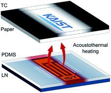
Polydimethylsiloxane, the most common microchannel material, effectively absorbs acoustic waves and converts the acoustic energy into thermal energy. Here, we quantitatively characterize this phenomenon and develop a heating platform that offers spatiotemporal temperature control in two dimensions. We demonstrate the use of this heating platform to innovate thermochromic displays (TCDs). A TCD comprises a display layer covered with a thermochromic substance and a heater attached to the bottom of the display layer. The thermochromic substance is opaque at room temperature and becomes translucent when heated beyond a transition temperature. Consequently, the TCDs deliver visual information concealed beneath the thermochromic substance by controlling the temperature of the display layer. The previously reported TCDs have limitations including restricted flexibility in display information and cumbersome spatiotemporal temperature control. We address these limitations by developing a disposable TCD system using our spatiotemporally controllable heating platform. The utility of the proposed system is demonstrated in shutter-type TCDs for coloured, intricate picture displays, as well as in segment-type TCDs for on-demand information displays of alphanumeric characters. Finally, we propose a new type of TCD that can represent colour gradients based on the ability of the heating technique to generate free-form, continuous temperature gradients.


Introduction

Surface acoustic waves (SAWs) are mechanical waves that travel along the surface of a medium. SAWs have attracted considerable interest for a variety of microfluidic operations due to the following advantages. First, fluid-structural coupling of SAWs is remarkably efficient and effective, with a vibration velocity of the order of 1 m s−1 and an acceleration of the order of 107 m s−2, because most of the acoustic energy is confined near the surface.1 Second, SAW devices are simple and inexpensive to fabricate using conventional photolithography, small enough to be integrated onto chip-scale substrates, and easy to operate by simply applying an electrical signal.2 Third, the SAW devices can be made portable using a palm-sized, CR123 battery-powered driver circuit3 and even flexible when built on a bendable plastic film.4 Thus, SAWs have been extensively utilized for micro-object (particle,1,5,6 bubble,1,6–8 droplet,1,6,9,10 and cell1,6,11,12) manipulation in fluids and for fluid actuation (mixing,1,6,13,14 pumping,1,6,15,16 jetting,1,6,17 and atomization1,6,18,19).

SAW-based microfluidic systems are commonly fabricated using polydimethylsiloxane (PDMS) as the microchannel material owing to its easy and low-cost fabrication process; however, the PDMS microchannels effectively absorb the acoustic energy of SAWs and in turn produce unintentional heat during SAW system operation.16 This energy conversion from acoustic to thermal is called acoustothermal heating. Unfortunately, the acoustothermal heating may cause operational drawbacks such as alterations in the physical properties of the liquid samples and microchannels, local boiling of the liquid samples, and deformation of the microchannel. Therefore, this heating phenomenon has been considered to be an undesirable side effect. Researchers have avoided this side effect by maintaining the operating temperature of SAW devices using a cooling element, such as a Peltier cooler, to remove heat.20–22

We recently noted the utility of the acoustothermal heating in PDMS microfluidic channels and designed a new type of microfluidic heater based on this principle.23,24 An acoustothermal heater is composed of a conventional SAW system and a PDMS microchannel. The SAW system comprises interdigital transducers (IDTs) deposited onto a piezoelectric substrate, and the PDMS microchannel consists of a thin membrane and an embossed microstructure. The thin PDMS membrane plays a critical role in absorbing the acoustic energy of SAWs. The thin PDMS membrane is thus heated by acoustothermal heating and transfers heat to the liquid samples. The acoustothermal heating was found to be rapid (≥2000 K s−1), volumetric, and energy-efficient.23 One of the attractive aspects of acoustothermal heating is its ability to produce multiple temperature zones using time-division multiplexed (TDM) AC signals, which will be elaborated in the subsequent section. The feasibility of our acoustothermal heating system was validated using a two-step continuous-flow polymerase chain reaction (CFPCR) system designed to amplify 134 bp DNA in less than 3 min.23 We proceeded further to develop a slanted interdigital transducer-based acoustothermal heater to dynamically generate free-form temperature profiles in a disposable microchip. The linear temperature profile formed on the microchip enabled one-shot high-resolution melting analysis to detect single nucleotide polymorphisms in DNA.24

Here, we explored the utility of acoustothermal heating in thermochromic display (TCD) systems. Many point-of-care (POC) diagnostic systems include ambiguous displays of test results that can lead to misinterpretation of the displayed information.25,26 TCDs present an alternative approach to test outcome displays in POC diagnostics.27 Thermochromism is a reversible, temperature-dependent change of colour.28 This temperature-dependent colour transition is used in TCD devices to deliver visual information via a thermochromic substance-containing layer mounted on a heater. The TCDs can precisely represent visual information, and they offer significant advantages including simple and inexpensive fabrication requirements, easy operation, and integrability into other microfluidic devices. Among the various TCDs reported to date,27,29–33 the simplest form is shutter-type TCDs based on the colour change of thermochromic ink, from black to translucent, at the ink's transition temperature. The ink is coated onto a substrate, in which visual information is pre-printed, and conceals (shut) or reveals (open) the visual information depending on the temperature. Siegel et al. developed a paper-based TCD by depositing a thermochromic ink layer and patterning electrically conductive wires that acted as a heater onto the front and back sides of the paper substrate, respectively.27 Their paper-based TCD system was low-cost, light-weight, and structurally flexible. Nevertheless, its application has been limited because only pre-selected messages concealed under the thermochromic ink layer could be displayed, offering restricted flexibility in the displayed information.33

Segment-type TCDs have been proposed to address the limitations of shutter-type TCDs. Shin et al. designed a paper-based, seven-segment TCD system and applied it to numerical displays (0–9).33 The limitations imposed by the need to pre-print information were resolved to some extent, but their seven-segment thermochromic display was still limited in its ability to express only numbers. Liu et al. developed a TCD using a carbon nanotube (CNT) film heater array and applied it to Chinese character and number displays.32 Despite their excellent resolution (16 × 16 segments) compared to Joule heater-integrated TCDs, technological advances are still needed to resolve several pending problems: the device fabrication is complicated and costly, the surface roughness tends to be high, and the surface energy tends to be low.34–36 In addition, the abovementioned TCD systems have common limitations. First, a single heater unit cannot be reused in another display component, thereby limiting each heater unit to a single-purpose display.

In the present study, we propose an improved thermochromic display system that uses acoustothermal heating to address the abovementioned limitations of the TCD systems reported to date. Following our earlier work on acoustothermal heating,23,24 we performed an in-depth characterization of the heating mechanism. Based on the results, we developed a heating platform that provides spatiotemporal temperature control using TDM AC signals, and we tailored this system to TCD applications. In the proposed TCD system, a heater and a display layer were attached in a separable manner to allow disposability of the display layer. The flexibility of the display information was thereby significantly improved as the display contents could be easily changed by replacing the display layer. We demonstrated the capability of the shutter-type TCDs to display coloured, intricate pictures, and the segment-type TCDs were developed to display on-demand information in alphanumeric characters. In addition, we presented a new type of TCD that could display colour gradients based on a continuous temperature profile. Such temperature gradients were previously unattainable using conventional heating methods. We postulate that the proposed TCD system can be utilized as a disposable display system in POC diagnostics that can be integrated into other SAW-based microfluidic devices.

Materials and methods

Device fabrication

Fig. 1(a) illustrates a conventional SAW system composed of a pair of uniformly spaced metal electrodes (IDT) deposited onto a piezoelectric substrate (e.g., LiNbO3; LN). The IDT resonates to emanate SAWs in two opposite directions with a frequency of fSAW, only when the frequency of an applied AC signal (fAC) corresponds to the IDT spacing (λ/4) such that fAC = cs/λ = fSAW where cs is the speed of sound in the substrate. As shown in Fig. 1(b), the proposed TCD system consisted of an acoustothermal heater and a disposable TCD layer. The heater was composed of an IDT patterned onto the LN substrate and a thin PDMS membrane. The IDT (Cr/Au: 300 Å/2000 Å) was deposited using e-beam evaporation onto the LN substrate (128° Y-cut X-propagating LiNbO3, MTI Korea, Korea) in a single step lift-off process using a single chrome photomask. The PDMS base and curing agent (Sylgard 184A and 184B, Dow Corning, USA) were mixed in a ratio of 10[thin space (1/6-em)]:[thin space (1/6-em)]1 to produce a thin PDMS membrane by spin-coating at 260 rpm for 30 s and curing in an oven at 90 °C for 2 h. The thickness of the PDMS membrane was controlled according to the empirical equation presented by Zhang et al.37,38 The PDMS membrane was uniformly contacted and reversibly bonded to the LN substrate owing to the high surface energy of PDMS. The disposable display layer was composed of an adhesive label paper sheet (#21301-100, 3M, Korea) and an adhesive thermochromic (TC) film (NANO I&C, Korea) that changed its colour from black to translucent over a transition temperature of 40 °C (see the ESI Fig. S1(a)). The thicknesses of the LN/PDMS/paper/TC layers were 500/400/100/125 μm, respectively.
image file: c6ra04075f-f1.tif
Fig. 1 (a) A conventional surface acoustic wave (SAW) system composed of a piezoelectric substrate (LiNbO3; LN) and an interdigital transducer (IDT) patterned onto the LN substrate; (b) the proposed TCD system composed of an acoustothermal heater and a disposable thermochromic (TC) display layer.

Working mechanism

In the acoustothermal heater, the SAWs propagating on the LN substrate immediately refracted into the PDMS membrane in the form of longitudinal waves (LWs) due to a mismatch between the speeds of sound in PDMS (cp ≈ 1100 m s−1) and LN (cs ≈ 4000 m s−1). The refraction occurred at a small angle of refraction (θ) of approximately 16° pursuant to Snell's law such that θ = sin−1(cp/cs) ≈ 16°. The acoustic energy of the LWs was then transformed into thermal energy (heat) as the acoustic waves were absorbed into the PDMS membrane via viscoelastic damping. The damping capability could be quantified by calculating loss tangent tan(η) = E′′/E′, which indicates the acoustic energy lost per cycle, where E′′ and E′ represent the storage and loss moduli in the complex modulus E* = E′ + iE′′, respectively.39 When the frequency of the incident acoustic waves matched with the natural frequency of the polymer chains, the damping capability of the polymer reached its maximum.39 Because the absorbed acoustic energy was converted into heat, the most energy-efficient acoustothermal heating occurred at the frequency of maximum viscoelastic damping. The penetration depth δ of the acoustothermal heating, at which the acoustic power of the propagating LWs is reduced by one-half, was found to abide by the power law δfSAW−0.7.23 Over the frequency range 20–45 MHz used in the present study, the corresponding penetration depths varied over the range 700–450 μm, deep enough to cover the PDMS membrane (400 μm). Therefore, the PDMS membrane was volumetrically heated as the acoustic waves travelled through the membrane. The small angle of refraction at the LN/PDMS interface and volumetric heating enabled localized heating of the display layer.

Device operation

The TDM AC signals shown in Fig. 2(a) comprise a set of multiple AC signals with different frequencies that are sequentially separated with a time interval τ. These signals enable selective actuation of each IDT in an IDT array because each IDT intrinsically resonates only under an incident AC signal with a resonant frequency, leading to spatiotemporally controllable acoustothermal heating. TDM AC signals with multiple frequencies were produced from an RF signal generator (N5171B-501, Keysight Technologies, USA) controlled by a MATLAB in-house code and amplified using a power amplifier (ZHL-100W-GAN+, Mini-Circuits, USA) with a DC power supply (E3634A, Keysight Technologies, USA). For example, a 1 × 3 IDT array with resonant frequencies of f1, f2, and f3 in Fig. 2(b) could be selectively actuated using TDM AC signals that included these specific resonant frequencies (a detailed description of the IDT array provided below in the subsequent section). The yellow solid line represents the position at which the TCD layer was deposited. As shown in Fig. 2(c), the application of TDM AC signals, with frequencies of f1 and f3, and with τ = 100 μs, only heated the areas corresponding to f1 and f3, and the colours of these areas changed from black to opaque white as the white paper sheet beneath the thermochromic film was revealed. An IR image of the display was measured using an IR camera (A325sc, FLIR Systems, USA) to confirm the spatiotemporally controlled heating of our display system.
image file: c6ra04075f-f2.tif
Fig. 2 (a) Time-division multiplexed (TDM) AC signals; (b) a 1 × 3 IDT array with three resonant frequencies of f1, f2, and f3 (the position of the TCD layer represented with the yellow solid line); (c) a photograph and an IR image of the TCD upon application of TDM AC signals at f1 and f3.

Results and discussion

Characterization of acoustothermal heating

The temperature increase via acoustothermal heating was proportional to the electrical power applied to the IDTs; however, the energy conversion efficiency of PDMS depended on the frequency of the incident acoustic waves due to the frequency-dependent damping capability. The relation between the electrical power and the temperature increase was characterized as a function of the frequency of an AC signal applied to an IDT. We therefore characterized the intensity of the electrical power required to actuate an IDT for TCD operation as a function of the IDT frequency. In a previous study, we reported the frequency dependent acoustothermal heating with its maximum heating capability at a frequency of around 30 MHz.23 We further investigated the heating process in terms of the power density, which is the electrical power applied per unit area, at different IDT frequencies. Fig. 3 plots the temperature increase ΔT (K) as a function of the power density Pd (mW mm−2) in 9 acoustothermal heaters in a 3 × 3 IDT array (20.3, 23.3, 25.8, 28.7, 31.5, 34.5, 37.5, 40.0, and 42.5 MHz). The solid lines indicate the linear fits of the discrete data points. The temperature increase was measured 5 s after the SAW excitation, and the results from five independent experiments were averaged over each heater area (2 × 2 mm2). Regardless of the IDT resonant frequency, the temperature increase was found to be proportional to the power density applied to the IDT such that ΔTPd. This relationship suggested that the temperature of the proposed TCD could be controlled by modulating the electrical power density applied to the IDT. Note that the acoustothermal heater provided uniform heating with a standard deviation over each heater of less than 1 K, irrespective of the IDT frequency. However, the slope of the Pd–ΔT profiles varied with the IDT resonant frequencies, indicating the frequency-dependent thermal behaviour of the thin PDMS membrane in the heater.
image file: c6ra04075f-f3.tif
Fig. 3 Power density–temperature increase profiles of the acoustothermal heaters in a 3 × 3 IDT array with resonant 9 frequencies (20.3, 23.3, 25.8, 28.7, 31.5, 34.5, 37.5, 40.0, and 42.5 MHz). The linear fits of the discrete data points represented by solid lines. The temperature increase was measured 5 s after the SAW excitation, and the results from five independent experiments were averaged over each heater area (2 × 2 mm2).

The frequency dependent acoustothermal heating can be clearly observed in Fig. 4, which shows the temperature increase at Pd = 10 mW mm−2 (black symbols) and the power density required to achieve ΔT = 25 K as a function of the IDT resonant frequency. The solid lines indicate 4th-order polynomial fits to the discrete data points. At a fixed power density, the temperature increase varied depending on the IDT frequency with its maximum of 66.04 K at 31.5 MHz. Similarly, the power density required to achieve ΔT = 25 K varied depending on the IDT frequency with its minimum of 3.85 mW mm−2 at 31.5 MHz. The energy conversion efficiency from electrical to acoustic and finally to thermal could be measured from the temperature increase at a given power density. The frequency range of 25–40 MHz was appropriate for low-power-consumption TCDs (≤10 mW mm−2 for ΔT = 25 K), which were more energy-efficient than those using a CNT film heater with an area of 2 × 2 mm2.32 Fig. 4 suggests an approach to designing and controlling a TCD system using multiple acoustothermal heaters in an IDT array. The IDT frequency and electrical power density required for a given IDT frequency were carefully selected to achieve energy-efficient TCD operation. It should be noted that the electrical power was measured at the output terminal of the amplifier. This caused slight different results from those reported previously,23 in which the measurements were conducted without calibrating of the frequency-dependent performance of the signal generator and amplifier. The large standard deviation of the temperature increase observed in the previous measurements was dramatically alleviated to less than 1.5 K, regardless of the IDT frequency. The steep temperature increase profile also shifted to provide a smooth profile with a peak at a higher IDT frequency of around 32.5 MHz.


image file: c6ra04075f-f4.tif
Fig. 4 Temperature increase at a power density of 10 mW mm−2 (black symbols) and the power density required for a temperature increase of 25 K (white symbols). The 4th-order polynomial fits to the discrete data points are represented by solid lines.

The heating rate is an important consideration for achieving rapid thermal actuation. Unlike surface heating methods (e.g., Joule heating, CNT film heating) that transfer heat by conduction, the proposed acoustothermal heating is volumetric, leading to rapid heating. Fig. 5 shows a periodic temperature profile of a TCD layer upon heating over 5 s (Pd = 3.85 mW mm−2) and cooling for 20 s, which was deposited onto an acoustothermal heater with fSAW = 31.5 MHz and an area of 2 × 2 mm2. The thermochromic colour transition as a function of the temperature is represented in symbol colour. The heating proceeded rapidly, with a maximum instantaneous heating rate above 2000 K s−1, because the high-frequency acoustic waves rapidly propagated into the PDMS membrane to simultaneously generate heat. The cooling process by natural convection was also fast without the need for an additional cooling element due to the small thermal mass of the system.23 A slight lag in the colour transition from opaque white back to black was observed during cooling due to the thermochromic hysteresis of the film between heating and cooling (see the ESI Fig. S1(a)).


image file: c6ra04075f-f5.tif
Fig. 5 Periodic temperature profile of a TCD layer upon heating over 5 s (Pd = 3.85 mW mm−2) and cooling for 20 s. The TCD layer was deposited onto an acoustothermal heater with fSAW = 31.5 MHz and an area of 2 × 2 mm2. Thermochromic colour transition is represented by the symbol colour.

Shutter-type TCDs

Many POC diagnostics rely on colorimetric representation to display their test outcomes.40 With this application in mind, we developed thermochromic colour display systems that could reduce ambiguity in colour representation. Fig. 6(a) shows a 1 × 3 IDT array with actual resonant frequencies of f1f3 (24.5, 29.3, and 34.3 MHz) and a pixel area of 3 × 3 mm2. The yellow solid line represents the position at which the TCD layer was deposited. As explained above, the spatiotemporally controllable acoustothermal heating under applied TDM AC signals enabled the selective actuation of the TCDs. We demonstrated two types of colour displays, as shown in Fig. 6(b) and (c). First, it was possible to display any colour that had been pre-printed on the paper sheet and covered by a black thermochromic film that became translucent at a temperature above a transition temperature of 40 °C (see the ESI Fig. S1(a)). As an example, RGB coloured-pixels were selectively displayed, as shown in Fig. 6(b). The application of TDM AC signals with frequencies corresponding to the target pixels selectively heated the pixels above 50 °C and thus exposed the colours concealed beneath the thermochromic film. In this shutter-type configuration, only pre-printed colours could be displayed when the thermochromic film was heated above the transition temperature. Second, Fig. 6(c) shows a multi-phase colour transition of a thermochromic film with two colour transition temperatures of 40 °C (from blue to orange) and 60 °C (from orange to yellow). By modulating the power density applied to each pixel, we constructed three-step temperature profiles of 30, 50, and 70 °C, corresponding to blue, orange, and yellow colours, respectively. It should be noted that a paper sheet was not required in the TCD layer. This type of colour display enabled the proposed TCDs to deviate from pre-programmed colour displays at each pixel. It also suggested its potential utility for a variety of colour display applications in combination with the recently developed thermochromic pigments in the industry. Taking one step further, we fabricated a 2 × 2 IDT array-based TCD device for confusion matrix displays, as shown in Fig. 6(d). The device comprised a 2 × 2 IDT array with actual resonant frequencies of f1f4 (24.5, 29.3, 34.3, and 39.1 MHz) and each pixel area of 5 × 5 mm2. The yellow solid line represents the position at which the TCD layer was deposited. In binary classification-based diagnostic tests, statistical aspects of test results can be represented using a 2 × 2 confusion matrix for precise interpretation. Specifically, the sensitivity, specificity, and positive/negative predictive values of a diagnostic test can be calculated using the matrix.41 With this application in mind, we designed a shutter-type display of coloured pictures of thumbs-up and thumbs-down for use in a 2 × 2 confusion matrix display, as shown in Fig. 6(e). Depending on the test results, matching pictures pre-printed under the thermochromic film could be selectively displayed, indicating true positive (f1), false positive (f2), false negative (f3), and true negative (f4) results. In the shutter-type display configuration shown in Fig. 6, any coloured, intricate picture could be easily displayed without the use of a costly or complex display device.
image file: c6ra04075f-f6.tif
Fig. 6 (a) A 1 × 3 IDT array with three resonant frequencies of f1, f2, and f3 (24.5, 29.3 and 34.3 MHz) (the position of the TCD layer represented with the yellow solid line); (b) an RGB-coloured pixel display using the colour change of a thermochromic film from black to translucent; (c) blue/orange/yellow colour display using the colour change of a thermochromic film from blue to orange at 40 °C and from orange to yellow at 60 °C; (d) a 2 × 2 IDT array with four resonant frequencies of f1, f2, f3, and f4 (24.5, 29.3, 34.3, and 39.1 MHz); (e) a 2 × 2 confusion matrix display.

Segment-type TCDs

In some POC diagnostic tests, the results of an assay may be appropriately represented using language texts or numbers; however, the shutter-type TCD systems provide only pre-defined visual information in an on and off manner. To overcome this limitation, we fabricated a nine-segment TCD system for on-demand information displays using a 3 × 3 IDT array shown in Fig. 7(a). The yellow solid line represents the position at which the TCD layer was deposited. We previously presented a potential application of acoustothermal heating to obtain two-dimensional spatiotemporal temperature control using a 5 × 5 IDT array.23 In that work, the letters ‘K-A-I-S-T’ were patterned in an IR image by staking multiple IR images of individually actuated IDTs; however, the practical realization of this design was not accomplished because the IDT frequency difference, frequency range, and size were not optimized. Here, we realized two-dimensional spatiotemporal temperature control using an optimized 3 × 3 IDT array with a pixel area of 2 × 2 mm2. The results in Fig. 4 reveal that an IDT frequency difference of 3 MHz over the frequency range 20.3–42.5 MHz provided energy-efficient actuation of the TCDs. With these results in mind, the resonant frequencies of the 3 × 3 IDT array (f1f9) were designed to be 20.3, 23.3, 25.8, 28.7, 31.5, 34.5, 37.5, 40, and 42.5 MHz, respectively. Alphanumeric characters could be represented in 3 × 3 segments, allowing the display of on-demand information in these characters using a nine-segment TCD with a 3 × 3 IDT array. We demonstrated the capabilities of our TCD system by displaying numbers (‘2-0-1-6’) and English alphabets (‘K-A-I-S-T’), as shown in Fig. 7(b) and (c), respectively. Numbers from ‘0’ to ‘9’ and English alphabets from ‘A’ to ‘Z’ displayed in this configuration are shown in the ESI Fig. S2. Although the segment-type display's pixel resolution was low, this display system addressed the inherent limitation of the TCD system: limited flexibility in display information. Therefore, we anticipate that this display system will be applicable where information should be displayed in alphanumeric characters without a high pixel resolution.
image file: c6ra04075f-f7.tif
Fig. 7 (a) A 3 × 3 IDT array with resonant frequencies from f1f9 (20.3, 23.3, 25.8, 28.7, 31.5, 34.5, 37.5, 40, and 42.5 MHz) (the position of the TCD layer represented with the yellow solid line); (b) numeric display of ‘2-0-1-6’; (c) English alphabet display of ‘K-A-I-S-T’; numbers from ‘0’ to ‘9’ and English alphabets from ‘A’ to ‘Z’ displayed in this configuration are shown in the ESI Fig. S2.

Thermochromic colour gradient displays

Colour gradient displays are useful to represent spatially distributed information with a progressive change. However, none of the previously reported TCDs had the capability of displaying colour gradients. This is simply because a great number of heaters are required for a high-resolution heater array to form a continuous temperature gradient in conventional heating methods. Here, we suggest a slanted interdigital transducer (SIDT)-based acoustothermal heater to realize colour gradient displays. The SIDT-based acoustothermal heater offers the ability to generate continuous temperature gradients even as a single unit. Fig. 8(a) shows an SIDT having varying IDT spacing ranging from λ1 (198 μm) to λ2 (99 μm), corresponding to SAW frequencies from f1 (20 MHz) to f2 (40 MHz). The yellow solid line represents the position at which the TCD layer is to be deposited. The application of an AC signal, with a frequency of f where f1 < f < f2, to the SIDT activates the corresponding area having an IDT spacing of λ/4 where λ = cs/f on the SIDT, thereby producing SAWs with a frequency of fSAW = f. The free-from, dynamic generation of continuous temperature gradients could be obtained using an SIDT-based acoustothermal heater actuated by TDM AC signals. Thermochromic colour gradients can be realized by temperature gradients in TCDs. It can be difficult to form a continuous temperature gradient using a heater array unless fabricated with extremely high resolutions. By contrast, SIDT-based TCDs could display thermochromic colour gradients due to the ability of SIDT-based acoustothermal heating to generate free-form, continuous temperature gradients. This capability can be better understood by comparing a continuous linear temperature profile produced by a SIDT to a step-function like linear temperature profile produced by a 1 × 5 IDT array, as shown in the ESI Fig. S3. We demonstrated a thermochromic colour gradient display, as shown in Fig. 8(b), under a linear temperature profile ranging from 30 °C to 50 °C using a thermochromic film with gradual colour transition from black to translucent (see the ESI Fig. S1(b)). Under the temperature distribution 30–50 °C, a colour gradient from black to opaque white was formed in the TCD. The nonlinear normalized greyscale intensity resulted from the nonlinear thermal response of the thermochromic film.
image file: c6ra04075f-f8.tif
Fig. 8 (a) A SIDT with a resonant frequency range from f1 (20 MHz) to f2 (40 MHz) (the position of the TCD layer represented with the yellow solid line); (b) colour gradient displays; (c) confusion matrix displayed along one dimension; (d) 5-level displays.

In addition to colour gradient TCDs, the SIDT-based TCD can be utilized as one-dimensional shutter-type TCDs. The use of TDM AC signals with multiple frequencies simultaneously actuates multiple areas of the SIDT, resulting in selective operation of one-dimensional TCDs. The 2 × 2 confusion matrix display shown in Fig. 6(e) could also be implemented in a one-dimensional manner using an SIDT-based TCD. Four types of test results (true positive, false positive, false negative, and true negative) were displayed by activating the corresponding areas using TDM AC signals to expose the pre-printed messages as shown in Fig. 8(c). The ‘T’ in the green background colour, ‘F’ in the red background colour, ‘plus’ and ‘minus’ symbols indicate ‘true’, ‘false’, ‘positive’, and ‘negative’, respectively. Furthermore, the SIDT-based acoustothermal heater could also be used for level displays for semi-quantitative representation, as pictured in Fig. 8(d). A thermochromic 5-level display was realized by actuating individual levels to obtain a temperature above the colour transition temperature of the thermochromic film. With the above applications of confusion matrix and level displays, we demonstrated that the SIDT-based acoustothermal heater can be utilized as one-dimensional shutter-type TCDs. Unlike other heating methods, only one unit of the SIDT-based acoustothermal heater is required for one-dimensional shutter-type TCDs composed of multiple segments, leading to a dramatic reduction in costs.

Conclusions

We designed a series of disposable TCD systems that provide spatiotemporally controllable acoustothermal heating. We investigated the properties of the acoustothermal heating and characterized its frequency dependence on temperature increase and power density. These characterization studies were used to develop an optimized heating platform for TCD applications that offered spatiotemporal temperature control in two dimensions using TDM AC signals. The proposed TCD system comprised an acoustothermal heater and a TCD layer that were attached in a separable manner, thereby enabling disposability of the TCD layer. Unlike the heater-integrated configuration, the disposability of the display layer enabled a single heater to be used for versatile displays simply by replacing the display layer. The disposability addresses limitations on flexibility of display information in the shutter-type TCDs. This feature offers a rational, long-term countermeasure to the relatively expensive acoustothermal heater compared to the paper-based heater. We demonstrated the utility of the proposed TCD system in POC diagnostic applications using a variety of display types: shutter-type, segment-type, and colour gradient displays. The shutter-type displays demonstrated that an intricate picture with multiple colours could be displayed. Alphanumeric characters could be displayed using a nine-segment thermochromic display system for on-demand information displays. In addition, we demonstrated a new type of TCD that could represent colour gradients based on the ability of acoustothermal heating to produce free-form, continuous temperature gradients. In conclusion, the proposed TCD system can deliver complex information easily at low cost with disposability and significantly improved flexibility in display information. We envisage that the proposed TCD systems may find application in POC diagnostics, in which information should be unambiguously displayed to allow the correct interpretation of test outcomes.

Acknowledgements

This work was supported by the Creative Research Initiatives (no. 2015-001828) program of the National Research Foundation of Korea (MSIP) and the KUSTAR-KAIST Institute.

References

  1. L. Y. Yeo and J. R. Friend, Annu. Rev. Fluid Mech., 2014, 46, 379–406 CrossRef.
  2. Y. Q. Fu, J. K. Luo, X. Y. Du, A. J. Flewitt, Y. Li, G. H. Markx, A. J. Walton and W. I. Milne, Sens. Actuators, B, 2010, 143, 606–619 CrossRef CAS.
  3. A. Qi, J. R. Friend, L. Y. Yeo, D. A. Morton, M. P. McIntosh and L. Spiccia, Lab Chip, 2009, 9, 2184–2193 RSC.
  4. H. Jin, J. Zhou, X. He, W. Wang, H. Guo, S. Dong, D. Wang, Y. Xu, J. Geng, J. K. Luo and W. I. Milne, Sci. Rep., 2013, 3, 2140 Search PubMed.
  5. D. J. Collins, T. Alan and A. Neild, Lab Chip, 2014, 14, 1595–1603 RSC.
  6. G. Destgeer and H. J. Sung, Lab Chip, 2015, 15, 2722–2738 RSC.
  7. L. Meng, F. Cai, Z. Zhang, L. Niu, Q. Jin, F. Yan, J. Wu, Z. Wang and H. Zheng, Biomicrofluidics, 2011, 5, 44104–4410410 Search PubMed.
  8. L. Meng, F. Cai, J. Chen, L. Niu, Y. Li, J. Wu and H. Zheng, Appl. Phys. Lett., 2012, 100, 173701 Search PubMed.
  9. T. Franke, A. R. Abate, D. A. Weitz and A. Wixforth, Lab Chip, 2009, 9, 2625–2627 RSC.
  10. M. Sesen, T. Alan and A. Neild, Lab Chip, 2014, 14, 3325–3333 RSC.
  11. X. Ding, Z. Peng, S.-C. S. Lin, M. Geri, S. Li, P. Li, Y. Chen, M. Dao, S. Suresh and T. J. Huang, Proc. Natl. Acad. Sci. U. S. A., 2014, 111, 12992–12997 CrossRef CAS PubMed.
  12. M. Antfolk, C. Magnusson, P. Augustsson, H. Lilja and T. Laurell, Anal. Chem., 2015, 87, 9322–9328 CrossRef CAS PubMed.
  13. R. Shilton, M. K. Tan, L. Y. Yeo and J. R. Friend, J. Appl. Phys., 2008, 104, 014910 CrossRef.
  14. A. R. Rezk, A. Qi, J. R. Friend, W. H. Li and L. Y. Yeo, Lab Chip, 2012, 12, 773–779 RSC.
  15. L. Schmid, A. Wixforth, D. A. Weitz and T. Franke, Microfluid. Nanofluid., 2011, 12, 229–235 CrossRef.
  16. S. M. Langelier, L. Y. Yeo and J. Friend, Lab Chip, 2012, 12, 2970–2976 RSC.
  17. P. K. Bhattacharjee, A. G. McDonnell, R. Prabhakar, L. Y. Yeo and J. Friend, New J. Phys., 2011, 13, 023005 CrossRef.
  18. M. Alvarez, J. Friend and L. Y. Yeo, Nanotechnology, 2008, 19, 455103 CrossRef PubMed.
  19. D. J. Collins, O. Manor, A. Winkler, H. Schmidt, J. R. Friend and L. Y. Yeo, Phys. Rev. E: Stat., Nonlinear, Soft Matter Phys., 2012, 86, 056312 CrossRef PubMed.
  20. P. Augustsson, R. Barnkob, S. T. Wereley, H. Bruus and T. Laurell, Lab Chip, 2011, 11, 4152–4164 RSC.
  21. C. Grenvall, C. Magnusson, H. Lilja and T. Laurell, Anal. Chem., 2015, 87, 5596–5604 CrossRef CAS PubMed.
  22. R. J. Shilton, V. Mattoli, M. Travagliati, M. Agostini, A. Desii, F. Beltram and M. Cecchini, Adv. Funct. Mater., 2015, 25, 5895–5901 CrossRef CAS.
  23. B. H. Ha, K. S. Lee, G. Destgeer, J. Park, J. S. Choung, J. H. Jung, J. H. Shin and H. J. Sung, Sci. Rep., 2015, 5, 11851 CrossRef PubMed.
  24. B. H. Ha, J. Park, G. Destgeer, J. H. Jung and H. J. Sung, Anal. Chem., 2015, 87, 11568–11574 CrossRef CAS PubMed.
  25. P. Yager, T. Edwards, E. Fu, K. Helton, K. Nelson, M. R. Tam and B. H. Weigl, Nature, 2006, 442, 412–418 CrossRef CAS PubMed.
  26. M. Usdin, M. Guillerm and A. Calmy, J. Infect. Dis., 2010, 201(Suppl 1), S73–S77 CrossRef PubMed.
  27. A. C. Siegel, S. T. Phillips, B. J. Wiley and G. M. Whitesides, Lab Chip, 2009, 9, 2775–2781 RSC.
  28. J. A. Compton, Color Res. Appl., 1984, 9, 15–22 CrossRef.
  29. L. Liu, S. Peng, W. Wen and P. Sheng, Appl. Phys. Lett., 2007, 90, 213508 CrossRef.
  30. O. Yarimaga, M. Im, Y.-K. Choi, T. W. Kim, Y. K. Jung, H. G. Park, S. Lee and J.-M. Kim, Macromol. Res., 2010, 18, 404–407 CrossRef CAS.
  31. L.-O. Hennerdal and M. Berggren, Appl. Phys. Lett., 2011, 99, 183303 CrossRef.
  32. P. Liu, L. Liu, K. Jiang and S. Fan, Small, 2011, 7, 732–736 CrossRef CAS PubMed.
  33. H. Shin, B. Yoon, I. S. Park and J. M. Kim, Nanotechnology, 2014, 25, 094011 CrossRef PubMed.
  34. V. Popov, Mater. Sci. Eng., R, 2004, 43, 61–102 CrossRef.
  35. S. K. Hwang, J. M. Lee, S. Kim, J. S. Park, H. I. Park, C. W. Ahn, K. J. Lee, T. Lee and S. O. Kim, Nano Lett., 2012, 12, 2217–2221 CrossRef CAS PubMed.
  36. G. Kalita, K. Wakita, M. Umeno, Y. Hayashi and M. Tanemura, Large-area CVD graphene as transparent electrode for efficient organic solar cells, 2012 38th IEEE, 2012, pp. 003137–003141 Search PubMed.
  37. Introduction to microlithography, ed. C. Willson, L. Thompson and M. Bowden, American Chemical Society, Washington, 1994 Search PubMed.
  38. W. Zhang, G. Ferguson and S. Tatic-Lucic, Elastomer-supported cold welding for room temperature wafer-level bonding, Micro Electro Mechanical Systems, 17th IEEE International Conference on (MEMS), 2004, pp. 741–744 Search PubMed.
  39. R. D. Corsaro and L. H. Sperling, Sound and vibration damping with polymers, American chemical society, 1990 Search PubMed.
  40. J. Hu, S. Q. Wang, L. Wang, F. Li, B. Pingguan-Murphy, T. J. Lu and F. Xu, Biosens. Bioelectron., 2014, 54, 585–597 CrossRef CAS PubMed.
  41. D. J. Lo, B. Kaplan and A. D. Kirk, Nat. Rev. Nephrol., 2014, 10, 215–225 CrossRef CAS PubMed.

Footnote

Electronic supplementary information (ESI) available: Additional results and experimental details. See DOI: 10.1039/c6ra04075f

This journal is © The Royal Society of Chemistry 2016
Click here to see how this site uses Cookies. View our privacy policy here.