Nanostructured charge transfer complex of CuTCNQF4 for efficient photo-removal of hexavalent chromium

Duong Duc Laa, Rajesh Ramanathan*b, Anushri Rananawarea, Vipul Bansal*b and Sheshanath V. Bhosale*a
aSchool of Science, RMIT University, GPO Box 2476, Melbourne, VIC 3001, Australia. E-mail: sheshanath.bhosale@rmit.edu.au
bIan Potter NanoBioSensing Facility, NanoBiotechnology Research Laboratory (NBRL), School of Science, RMIT University, GPO Box 2476, Melbourne, VIC 3001, Australia. E-mail: rajesh.ramanathan@rmit.edu.au; vipul.bansal@rmit.edu.au; Fax: +61 3 9925 3747; Tel: +61 3 9925 2121

Received 28th January 2016 , Accepted 21st March 2016

First published on 24th March 2016


Abstract

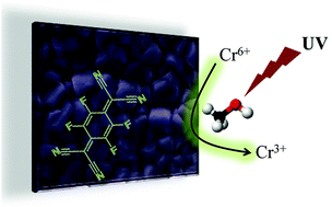
The high toxicity of hexavalent chromium warrants the development of efficient catalysts that could reduce chromium into relatively non-toxic trivalent chromium species. Pristine charge transfer complexes of the MTCNQ family (M = Cu or Ag; TCNQ = 7,7,8,8-tetracyanoquinodimethane) have previously failed to catalyse the reduction of Cr6+ to Cr3+. We demonstrate that due to the outstanding electron transfer properties of one of the fluorinated derivatives of MTCNQ, i.e., 7,7,8,8-tetracyano-2,3,5,6-tetraflouroquinodimethane (CuTCNQF4), it is able to catalyse the reduction of hexavalent chromium in aqueous solution at room temperature. We further demonstrate that the semiconducting nature of these organic charge transfer complexes allows CuTCNQF4 to act as an outstanding material for the reductive photo-removal of hexavalent chromium under UV photoexcitation conditions. Such materials are likely to play an important role in photoactive electron transfer reactions.
Introduction

Metal–organic semiconducting materials of the MTCNQ family (M = Cu or Ag; TCNQ = 7,7,8,8-tetracyanoquinodimethane) have attracted considerable attention over the last decade due to their potential applications in data and energy storage,1,2 sensors,3,4 electric devices,3–5 catalyst surfaces,6–9 and antibacterial materials.10 Fluorinated analogues of TCNQ, such as 7,7,8,8-tetracyano-2,3,5,6-tetraflouroquinodimethane (TCNQF4) have shown a significant improvement in the stability of the anion and dianion radicals in acetonitrile, while further improving their electron accepting properties, thereby enhancing the potential applicability of TCNQF4-based semiconducting materials.6,11,12 The synthesis and structural characterization of MTCNQF4 crystals have shown their outstanding optical, electrical, and magnetic properties13–20 compared to their non-fluorinated analogues. However, it is surprising that the applications of TCNQF4-based semiconducting materials have remained limited.11,12 Recently, the potential of CuTCNQF4 and AgTCNQF4 for electron transfer reactions between ferrocyanide and thiosulfate was investigated, and revealed that the balance between the injection of charge to the catalyst surface and the ejection of charge from the surface to the solution is an important factor in promoting this reaction.6 Similarly, CuTCNQF4 and AgTCNQF4 have also been used to fabricate field emission17 and switching devices.21

Hexavalent chromium, a carcinogen and mutagen, is a serious pollutant found in many industrial effluents, including metal plating, wood processing, pigment manufacturing and leather tanning.22,23 Chromium usually exists in two oxidation states viz. trivalent (Cr3+) and hexavalent (Cr6+) in aqueous solutions. While Cr3+ is minimally toxic to the environment and humans (it is even known as an essential nutrient for humans);24 Cr6+ remains extremely toxic to humans.25 It is also well-known that in comparison to Cr6+ that can easily migrate through groundwater and soil, Cr3+ can be readily precipitated in the form of Cr(OH)3 in aqueous solutions at neutral pH.26 This further negates the toxic effect of trivalent chromium in the environment. Therefore, it is of utmost importance to find effective ways to remove Cr6+ from aqueous solutions.

A facile approach for the removal of hexavalent chromium may involve the reduction of Cr6+ to Cr3+ followed by its precipitation to Cr(OH)3 in combination with other separation methods.27 Several strategies have been developed to reduce Cr6+ to Cr3+ in aqueous solution, including treatment with sulphur compounds or iron salts28,29 under acidic conditions followed by precipitation with an alkali, electrochemical reduction,30 photocatalytic reduction using semiconducting materials either by directly using the semiconductor for reduction or using the semiconductor as an adsorbent material followed by catalytic conversion in the presence of light illumination conditions31,32 and more recently bacteria33,34 and marine planktons.35 Among these strategies, the use of photocatalytic processes, wherein a semiconducting material is employed in combination with additional electron donors such as organic acids, is finding particular attention due to improved efficiencies.9,11,27,36 Although the use of inorganic semiconductors as photocatalysts is well-established,27,36 recent investigations have started to reveal that organic semiconductors decorated with noble metals can also effectively reduce Cr6+ to Cr3+.9 However, those studies found that pristine organic semiconductors without noble metals do not have enough driving force to catalyse this reaction. This is challenging, as noble metals typically add significant costs to the catalytic processes, which make their use impractical for environmental remediation.

In the current study, we report for the first time, the ability of a pristine organic semiconductor based on CuTCNQF4 in promoting the catalytic reduction of toxic Cr6+ to its non-toxic Cr3+ counterpart. The influence of reaction conditions including solution pH, electron donors, temperature, and UV light irradiation on the reduction efficiency is evaluated.

Materials and methods

Materials

Copper foil (99.99% purity) was procured from Chem Supply. Acetonitrile, concentrated sulphuric acid, nitric acid, methanol, acetic acid, and sodium dichromate (Na2Cr2O7) were purchased from Ajax Finechem. Tetrafluoro-1,4-benzoquinone was purchased from Sigma-Aldrich. All chemicals were used as received. TCNQF4 was synthesised in house. The copper foil was treated with dilute nitric acid, thoroughly rinsed with deionized water (MilliQ) and dried with a flow of N2 gas prior to use.

Synthesis of TCNQF4

The TCNQF4 synthesis was performed using a protocol reported previously.37 A suspension containing 5 mM of compound [1] in 150 mL of pyridine was added to 10 mM of TiCl4 (Scheme 1). This reaction mixture was slowly heated under a nitrogen atmosphere. To this heated mixture, 100 mM of malononitrile in 20 mL of dry pyridine was added and the reaction was refluxed for 15 h. At the end of 15 h, the reaction mixture was concentrated to half its volume. The solid product obtained after cooling was filtered, washed and dried in a vacuum oven. The product containing TCNQF4 was purified by recrystallization (methanol and acetonitrile) yielding a brown solid (TCNQF4) with 87% yield. Elemental analysis for C12F4N4: calculated: C – 52.19, N – 20.29; actual: C – 52.20, N – 20.29; FTIR using KBr disc, ν 3012 cm−1 (C–H aromatic), 2226 cm−1 (C[triple bond, length as m-dash]N), 1665 cm−1 (C[double bond, length as m-dash]C ring) and 1460 cm−1 (C–CN stretching); MALDI-TOF (m/z): [M+] calculated for C12F4N4: 276.0059, actual: 276.0057.
image file: c6ra02636b-s1.tif
Scheme 1 Synthesis of TCNQF4.

Synthesis of CuTCNQF4

Copper foil (2 × 0.5 cm2) was immersed in 6 mL of a 2 mM TCNQF4 solution at 45 °C for 3 h. The surface of the copper foil turned purple in colour indicating the formation of CuTCNQF4. The sample was rinsed several times with deionized water and dried in a stream of N2 gas prior to characterization.

Characterization of CuTCNQF4

The crystal structures and elemental composition of CuTCNQF4 grown on copper foil were studied by scanning electron microscopy (SEM) and energy dispersive X-ray spectroscopy (EDX) using an EDX-equipped Phillips XL30 SEM instrument. Fourier transform infrared spectroscopy (FTIR) was performed on a PerkinElmer D100 spectrometer in attenuated total reflectance mode, while Raman spectroscopy was performed using a PerkinElmer Raman Station 200F. The Raman spectra were background corrected using a smoothing free algorithm developed in house.38 X-ray photoelectron measurements (XPS) were carried out using a Thermo K-Alpha XPS instrument (Al Kα radiation, photon energy of 1486.6 eV). The C 1s, Cu 2p, N 1s and F 1s core level spectra were recorded with an overall resolution of 0.1 eV. The core level spectra were background corrected using the Shirley algorithm and chemically distinct species were resolved using a nonlinear least squares fitting procedure. UV-Vis reflectance measurements were carried out using a CRAIC Technologies microspectrophotometer with a 15× objective. The measurements were obtained from a 50 μm × 50 μm area.

Reduction of Cr6+

The catalysis experiments were carried out by placing CuTCNQF4 at the bottom of a 50 mL beaker containing a total 20 mL reaction volume with 10 mM of Cr6+ and 1 mL of electron donor (either dried methanol or acetic acid). The pH of the mixture was adjusted using 1 M H2SO4 before the reaction. CuTCNQF4 grown on 1 × 0.5 cm2 of foil was used for electron donor and pH-dependent catalytic experiments. For dark and UV irradiation (200 mW cm−2 UV with a λmax of 254 nm obtained from Edmund Optics) experiments, the Cu foil size on which CuTCNQF4 was grown was increased to 2 × 0.5 cm2 to increase the surface for light absorption. The sample was placed 2 cm away from the light source. The reaction mixture was continuously stirred at 250 rpm during the experiment. Samples were collected at different time points and examined using a Cary 50 UV-Vis spectrophotometer to determine the reduction of Cr6+ to Cr3+ by measuring the absorbance changes between 300 and 500 nm (characteristic absorption maxima λmax = 352 nm). For reusability experiments, the CuTCNQF4 catalyst grown on Cu foil was removed from the reaction vessel after completion of the reaction, followed by washing the catalyst surface three times with deionized water, before being used for the subsequent cycle for up to 10 cycles.

Results and discussion

The synthesis of TCNQF4 derivative [2] from precursor tetrafluoro-1,4-benzoquinone [1] was performed using a previously described protocol (Scheme S1).37 Briefly, the quinones present in [1] were reacted with malononitrile to form TCNQF4 [2], which was purified by precipitation and recrystallization from methanol and acetonitrile, and obtained as a crystalline high-temperature melting solid with 87% yield. The structure of TCNQF4 derivative [2] was confirmed by mass spectroscopy, elemental analysis (see Materials and methods) and FTIR.

The fabrication of CuTCNQF4 on copper foil proceeds through a one electron transfer reaction between copper metal and TCNQF4 in acetonitrile solution. During this process, a simple reduction of TCNQF40 dissolved in acetonitrile by Cu0 as the electron donor results in the formation of Cu+TCNQF4 crystals on the surface of the Cu foil. This is similar to what was observed in the case of CuTCNQ crystals formed on a copper foil.5–9,15 Illustrated in Fig. 1 are the SEM images of CuTCNQF4 crystals synthesised on both sides of a copper foil through a spontaneous crystallisation process in acetonitrile. These crystals show cuboidal morphology with an edge length of approximately 3 μm. The reaction time was optimised to obtain a uniform coating of the crystals throughout the surface of the copper foil, wherein a reaction time of 3 h yielded complete coverage of the copper foil with CuTCNQF4 crystals, while using 2 mM TCNQF4 at 45 °C.


image file: c6ra02636b-f1.tif
Fig. 1 (a) Low and (b) higher magnification SEM images of pristine CuTCNQF4 crystals synthesised on Cu foil in acetonitrile.

An EDX spectrum (Fig. 2a) obtained from the CuTCNQF4 crystals shows characteristic C Kα, N Kα, and F Kα energy lines at 0.277, 0.392 and 0.677 keV, respectively, which are attributed to TCNQF4 in the sample. An additional characteristic energy line for Cu Lα at 0.930 keV suggests the formation of CuTCNQF4 crystals. The calculated atomic ratios of C[thin space (1/6-em)]:[thin space (1/6-em)]F[thin space (1/6-em)]:[thin space (1/6-em)]N[thin space (1/6-em)]:[thin space (1/6-em)]Cu from the EDX measurements were 12[thin space (1/6-em)]:[thin space (1/6-em)]4[thin space (1/6-em)]:[thin space (1/6-em)]4[thin space (1/6-em)]:[thin space (1/6-em)]1, which is consistent with the expected stoichiometric ratio of the CuTCNQF4 elemental composition.17 Raman spectroscopy is an ideal technique to distinguish between neutral (TCNQF40) and reduced TCNQF4 (TCNQF4). Illustrated in Fig. 2b are background-corrected Raman spectra38 obtained from pristine TCNQF4 powder and CuTCNQF4. The pristine TCNQF4 powder shows characteristic signatures at 2226 cm−1 (C[triple bond, length as m-dash]N), 1665 cm−1 (C[double bond, length as m-dash]C ring) and 1460 cm−1 (C–CN stretching), confirming its neutral state (TCNQF40).6,15,17 Following the reaction of TCNQF4 with Cu, the C[triple bond, length as m-dash]N (2200 cm−1) and C[double bond, length as m-dash]C (1640 cm−1) bands shift to lower wavenumbers, confirming that the neutral TCNQF4 has converted to its reduced state (TCNQF4), signifying CuTCNQF4 formation.6,15,17 Furthermore, an important signature suggesting the formation of the TCNQF4 radical is the splitting of the C[triple bond, length as m-dash]N stretch, which indicates that the coordination between Cu+ and TCNQF4 is through the CN group.6,15,17 Additional peak shifts of the C–CN, C–C, and C–F stretching provides evidence for the presence of the TCNQF4 radical.6,15,17 The formation of CuTCNQF4 was also confirmed through the presence of characteristic FTIR bands at 2215, 1497 and 1223 cm−1 (Fig. S1, ESI).6,15 The presence of the 1497 cm−1 peak corresponding to the C[double bond, length as m-dash]C ring stretch, which is found at higher energy for TCNQF4, clearly suggests that the TCNQF4 units in CuTCNQF4 are present in their reduced form. In addition, the shift in the C–F out of plane bending at 1206 cm−1 also confirms the formation of CuTCNQF4.15,39


image file: c6ra02636b-f2.tif
Fig. 2 (a) EDX spectrum of CuTCNQF4 crystals; (b) Raman spectra of pristine TCNQF4 and CuTCNQF4 crystals.

Further evidence for the formation of CuTCNQF4 is evident from XPS measurements, wherein the Cu 2p core level XPS spectrum shows two characteristic 2p3/2 and 2p1/2 splitting components at 931.6 eV and 951.5 eV, respectively (Fig. 3). The absence of signatures corresponding to shake-up satellites suggests that the Cu species in CuTCNQF4 is present as Cu+, which corroborates well with the values reported in the literature.17,40,41 The N 1s core level XPS spectrum provides information about the involvement of the CN functional group during the formation of CuTCNQF4.5,7–9 In comparison to pristine TCNQF4 (Fig. S2, ESI), the N 1s core level spectrum of CuTCNQF4 shifts to a lower binding energy (BE) of 398.2 eV with an additional shake-up peak at a higher BE of 401.6 eV.18 This additional higher BE feature is due to the π–π conjugated system, a feature commonly observed in TCNQ and its derivatives.42 The BEs of C 1s and F 1s core level XPS spectra are also consistent with the reported values of TCNQF4.6,15,17


image file: c6ra02636b-f3.tif
Fig. 3 XPS spectra showing Cu 2p, N 1s, C 1s and F 1s core levels obtained from CuTCNQF4 crystals grown on a copper foil.

It is well-known that there is a considerable activation energy barrier during the reduction of Cr6+, even when a large driving potential is available during the reaction between Cr6+ and an electron donor. For instance, the reduction potentials (versus the standard hydrogen electrode) of the two-half equations, i.e. Cr6+ reduction and methanol oxidation, are 1.36 V and 0.02 V, respectively (E0 values).43 Therefore, even with a large driving potential of 1.34 V, the reaction does not proceed spontaneously and requires an efficient catalyst and/or high temperatures. This is probably the reason why non-fluorinated CuTCNQ could not catalyse Cr6+ reduction, even at high temperatures.9 However, when CuTCNQ was converted to CuTCNQ–metal hybrids, although Cr6+ could be reduced at ambient temperatures, elevated temperatures accelerated Cr6+ reduction.9 Given that the fluorinated analogues of TCNQ have superior electron accepting properties over TCNQ, in the current study, we assessed the performance of CuTCNQF4 as a potential catalyst for the reduction of hexavalent chromium in aqueous solutions at room temperature. In a typical reaction, the catalyst was immersed in an aqueous solution containing Cr6+ ions in the presence of acetic acid and methanol as electron donors, and held at a stable temperature of 25 °C. The UV-Vis spectra of the dichromate ions in the presence and absence of electron donors were measured as a function of time. It is apparent that while the reaction proceeds only in the presence of electron donors (Fig. 4a) due to ligand-to-metal charge transfer of dichromate ions;9,44 it is very interesting that pristine CuTCNQF4 could in fact catalyse Cr6+ reduction even at 25 °C. This is a significant advantage over non-fluorinated CuTCNQ, which remained inactive even at high temperatures for this particular reaction.9 Assuming that the reaction follows a pseudo-first-order kinetic model (the reaction proceeds in the presence of excess donor concentration), plotting the ln(At/A0) versus time (where At is the absorbance at time t and A0 is the absorbance at time zero) allows the determination of the rate constants. The relative rate constants for the reduction of Cr6+ at pH 2.0 in the presence of two electron donors, viz. methanol and acetic acid, were 2.5 × 10⁻³ min−1 and 2.0 × 10⁻³ min−1, respectively (Table S1, ESI). This suggests that methanol has a higher driving force over acetic acid in the presence of the catalyst and was therefore the choice of electron donor for subsequent studies. It is noteworthy that the reaction rates largely depend on the reaction conditions; therefore these rates are calculated for comparative purposes under similar reaction conditions.6,9,11


image file: c6ra02636b-f4.tif
Fig. 4 Plot of ln(At/A0) versus time for the CuTCNQF4 mediated reduction of Cr6+ (a) in the presence of different electron donors at pH 2.0 and 25 °C; (b) at different pH values in the presence of methanol at 25 °C and (c) at different temperatures in the presence of methanol and at pH 2.0.

Other reaction conditions such as the pH and temperature may also have a significant impact on the reaction rates. Hence, the catalytic conversion of Cr6+ was also performed at different pH values in the presence of methanol as an electron donor. Fig. 4b shows that at 25 °C, the reaction proceeds only under acidic pH conditions; such that while the reaction rates do not improve at pH values lower than 2.0, they dramatically drop at and above pH 3.0. Therefore, subsequent experiments were carried out at pH 2 in the presence of methanol. The role of pH in improving the reduction reaction is due to either an increase in oxidising ability of Cr6+ and/or the availability of more catalytically active sites through a reduction in the amount of Cr(OH)3 deposited on the catalyst surface.11,27 Fig. 4c shows the influence of temperature on the catalytic reduction of Cr6+, wherein while CuTCNQF4 was catalytically active at ambient temperatures, an increase in temperature from 25 to 50 °C did not significantly improve the reaction rates. This suggests that the outstanding electron transport properties of CuTCNQF4 may allow it to act as an efficient catalyst for even room-temperature reduction of hexavalent chromium.

The photocatalytic activity of traditional inorganic semiconductors such as TiO2, SnO2 and ZnO is well-known.45,46 Given that CuTCNQF4 also possesses semiconducting properties, we explored the possibility of improving the rate of Cr6+ reduction through photo-excitation. The absorption characteristics of CuTCNQF4 and pristine TCNQF4 suggested that while similar to traditional oxides,45 these molecules primarily absorb in the UV region, they also have absorbance across the visible region of the electromagnetic spectrum (Fig. S3, ESI).

Illustrated in Fig. 5 is the effect of UV light irradiation on the reduction of Cr6+. To assess the influence of UV light irradiation, the experiments were first carried out in the dark in the presence and absence of the catalyst. Under dark conditions, although the reaction proceeds faster in the presence of the catalyst, the reaction rate is not remarkably improved. In contrast, when the same reaction is carried out during UV light irradiation, the CuTCNQF4-mediated reduction of Cr6+ becomes significantly faster, such that the reaction rate is increased over an order of magnitude from 3.4 × 10⁻³ min−1 to 3.6 × 10⁻² min−1 in the presence of CuTCNQF4 (reaction rates for all reactions are outlined in Table S1, ESI). Notably, although the non-fluorinated analogue (CuTCNQ) was unable to promote the reduction of Cr6+,9 it is very interesting that the use of a fluorinated analogue (CuTCNQF4) in the current case could not only actively promote the catalytic reduction of Cr6+ even at room temperature, but the reaction rates could also be significantly enhanced by UV-light irradiation.


image file: c6ra02636b-f5.tif
Fig. 5 Plot of ln(At/A0) versus time for CuTCNQF4-mediated photo-reduction of Cr6+ at pH 2 and 25 °C in the presence of methanol as an electron donor.

The reusability of the CuTCNQF4 catalyst was also evaluated by employing the same catalyst for 10 consecutive catalytic reactions, wherein the surface of the catalyst was washed several times with deionised water between two reactions. The efficiency of the Cr6+ reduction was maintained for at least 10 cycles with no loss of efficiency (Fig. S4, ESI). In addition, the stability of the catalyst was also ascertained using SEM and Raman spectroscopy. No structural change was observed to the catalyst surface as seen from the SEM images (Fig. S5, ESI). The Raman spectra obtained before and after the catalytic reaction showed no change in the chemical composition (Fig. S6, ESI) further demonstrating the high stability of CuTCNQF4.

Conclusions

In summary, we have shown the fabrication of a nanostructured CuTCNQF4 organic charge transfer complex on copper foil by employing a facile redox reaction in acetonitrile. While non-fluorinated CuTCNQ is known to be inactive towards the reduction of hexavalent chromium, for the first time, its fluorinated derivative CuTCNQF4 is demonstrated to catalytically promote this reaction in aqueous solutions at room temperature. Importantly, under UV photo-excitation conditions, CuTCNQF4 could enhance the rate of this reaction by an order of magnitude over that in the dark. Given the ability of CuTCNQF4 in promoting catalytic reactions that are not successfully catalysed by its non-fluorinated analogues, the outcomes presented here open up a new avenue for employing fluorinated MTCNQ type organic semiconductors for reductive photocatalysis applications.

Acknowledgements

D. D. L. thanks RMIT University for financial support. R. R. thanks RMIT University for a Vice Chancellor’s Research Fellowship. V. B. and S. V. B. acknowledge the Australian Research Council for ARC Future Fellowships (FT140101285, FT110100152). V. B. also acknowledges the generous support of the Ian Potter Foundation for establishing an Ian Potter NanoBioSensing Facility at RMIT University. The authors acknowledge the support from the RMIT Microscopy and Microanalysis Facility (RMMF) for technical assistance and providing access to characterization facilities.

Notes and references

  1. H. L. Peng, C. B. Ran, X. C. Yu, R. Zhang and Z. F. Liu, Adv. Mater., 2005, 17, 459–464 CrossRef CAS.
  2. C. Ran, H. Peng, W. Zhou, X. Yu and Z. Liu, J. Phys. Chem. B, 2005, 109, 22486–22490 CrossRef CAS PubMed.
  3. R. Ramanathan, A. E. Kandjani, S. Walia, S. Balendhran, S. K. Bhargava, K. Kalantar-zadeh and V. Bansal, RSC Adv., 2013, 3, 17654–17658 RSC.
  4. R. Ramanathan, S. Walia, A. E. Kandjani, S. Balendran, M. Mohammadtaheri, S. K. Bhargava, K. Kalantar-zadeh and V. Bansal, Langmuir, 2015, 31, 1581–1587 CrossRef CAS PubMed.
  5. A. Pearson, R. Ramanathan, A. P. O’Mullane and V. Bansal, Adv. Funct. Mater., 2014, 24, 7570–7579 CrossRef CAS.
  6. M. Mahajan, S. K. Bhargava and A. P. O’Mullane, RSC Adv., 2013, 3, 4440–4446 RSC.
  7. A. Pearson, A. P. O’Mullane, V. Bansal and S. K. Bhargava, Inorg. Chem., 2011, 50, 1705–1712 CrossRef CAS PubMed.
  8. A. Pearson, A. P. O’Mullane, S. K. Bhargava and V. Bansal, Inorg. Chem., 2012, 51, 8791–8801 CrossRef CAS PubMed.
  9. A. Pearson and A. P. O’Mullane, ChemPlusChem, 2013, 78, 1343–1348 CrossRef CAS.
  10. Z. M. Davoudi, A. E. Kandjani, A. I. Bhatt, I. L. Kyratzis, A. P. O’Mullane and V. Bansal, Adv. Funct. Mater., 2014, 24, 1047–1053 CrossRef CAS.
  11. M. Mohammadtaheri, R. Ramanathan and V. Bansal, Catal. Today, 2016 DOI:10.1016/j.cattod.2015.1011.1017.
  12. A. Nafady, A. P. O’Mullane and A. M. Bond, Coord. Chem. Rev., 2014, 268, 101–142 CrossRef CAS.
  13. D. A. Dixon, J. C. Calabrese and J. S. Miller, J. Phys. Chem., 1989, 93, 2284–2291 CrossRef CAS.
  14. T. H. Le, A. Nafady, N. T. Vo, R. W. Elliott, T. A. Hudson, R. Robson, B. F. Abrahams, L. L. Martin and A. M. Bond, Inorg. Chem., 2014, 53, 3230–3242 CrossRef CAS PubMed.
  15. M. Mahajan, S. K. Bhargava and A. P. O’Mullane, Electrochim. Acta, 2013, 101, 186–195 CrossRef CAS.
  16. S. A. O’Kane, R. Clérac, H. Zhao, X. Ouyang, J. R. Galán-Mascarós, R. Heintz and K. R. Dunbar, J. Solid State Chem., 2000, 152, 159–173 CrossRef.
  17. C. Ouyang, Y. Guo, H. Liu, Y. Zhao, G. Li, Y. Li, Y. Song and Y. Li, J. Mater. Chem. C, 2009, 113, 7044–7051 CAS.
  18. J. Wang, W. Xu, J. Wu, G. Yu, X. Zhou and S. Xu, J. Mater. Chem. C, 2014, 2, 2010–2018 RSC.
  19. J. Wang, W. Xu, J. Zhang and S. Xu, J. Mater. Chem. C, 2014, 118, 24752–24760 CAS.
  20. K. Xiao, M. Yoon, A. J. Rondinone, E. A. Payzant and D. B. Geohegan, J. Am. Chem. Soc., 2012, 134, 14353–14361 CrossRef CAS PubMed.
  21. R. S. Potember, T. O. Poehler, A. Rappa, D. O. Cowan and A. N. Bloch, Synth. Met., 1982, 4, 371–380 CrossRef CAS.
  22. N. Spanos, S. Slavov, C. Kordulis and A. Lycourghiotis, Colloids Surf., A, 1995, 97, 109–117 CrossRef CAS.
  23. P. R. Wittbrodt and C. D. Palmer, Environ. Sci. Technol., 1995, 29, 255–263 CrossRef CAS PubMed.
  24. L. E. Eary and D. Rai, Environ. Sci. Technol., 1988, 22, 972–977 CrossRef CAS PubMed.
  25. X. Wang, J. Wang, L. Chang, Q. Ding, H. Liu and X. Jiang, RSC Adv., 2012, 2, 12315–12321 RSC.
  26. H. Gu, S. B. Rapole, J. Sharma, Y. Huang, D. Cao, H. A. Colorado, Z. Luo, N. Haldolaarachchige, D. P. Young, B. Walters, S. Wei and Z. Guo, RSC Adv., 2012, 2, 11007–11018 RSC.
  27. M. Valari, A. Antoniadis, D. Mantzavinos and I. Poulios, Catal. Today, 2015, 252, 190–194 CrossRef CAS.
  28. S. S. Chen, C. Y. Cheng, C. W. Li, P. H. Chai and Y. M. Chang, J. Hazard. Mater., 2007, 142, 362–367 CrossRef CAS PubMed.
  29. M. Gheju and A. Iovi, J. Hazard. Mater., 2006, 135, 66–73 CrossRef CAS PubMed.
  30. C. Barrera-Díaz, F. Ureña-Nuñez, E. Campos, M. Palomar-Pardavé and M. Romero-Romo, Radiat. Phys. Chem., 2003, 67, 657–663 CrossRef.
  31. R. Abe, J. Photochem. Photobiol., C, 2010, 11, 179–209 CrossRef CAS.
  32. F. Zheng, X. Lin, H. Yu, S. Li and X. Huang, Sens. Actuators, B, 2016, 226, 500–505 CrossRef CAS.
  33. K. H. Cheung and J.-D. Gu, Int. Biodeterior. Biodegrad., 2007, 59, 8–15 CrossRef CAS.
  34. R. Singh, A. Kumar, A. Kirrolia, R. Kumar, N. Yadav, N. R. Bishnoi and R. K. Lohchab, Bioresour. Technol., 2011, 102, 677–682 CrossRef CAS PubMed.
  35. S.-X. Li, F.-Y. Zheng, H.-S. Hong, N.-S. Deng and L.-X. Lin, Mar. Environ. Res., 2009, 67, 199–206 CrossRef CAS PubMed.
  36. S. C. Xu, S. S. Pan, Y. Xu, Y. Y. Luo, Y. X. Zhang and G. H. Li, J. Hazard. Mater., 2015, 283, 7–13 CrossRef CAS PubMed.
  37. N. Martin, R. Behnisch and M. Hanack, J. Org. Chem., 1989, 54, 2563–2568 CrossRef CAS.
  38. A. E. Kandjani, M. J. Griffin, R. Ramanathan, S. J. Ippolito, S. K. Bhargava and V. Bansal, J. Raman Spectrosc., 2013, 44, 608–621 CrossRef CAS.
  39. T. Le, A. O’Mullane, L. Martin and A. Bond, J. Solid State Electrochem., 2011, 15, 2293–2304 CrossRef CAS.
  40. S. R. Anderson, M. Mohammadtaheri, D. Kumar, A. P. O’Mullane, M. R. Field, R. Ramanathan and V. Bansal, Adv. Mater. Int., 2016, 3, 1500632 Search PubMed.
  41. R. Ramanathan, M. R. Field, A. P. O’Mullane, P. M. Smooker, S. K. Bhargava and V. Bansal, Nanoscale, 2013, 5, 2300–2306 RSC.
  42. J. M. Lindquist and J. C. Hemminger, J. Phys. Chem., 1988, 92, 1394–1396 CrossRef CAS.
  43. C. G. Zoski, Handbook of electrochemistry, Elsevier, Amsterdam, 2007 Search PubMed.
  44. C. E. Barrera-Díaz, V. Lugo-Lugo and B. Bilyeu, J. Hazard. Mater., 2012, 223–224, 1–12 CrossRef PubMed.
  45. A. Henglein, Chem. Rev., 1989, 89, 1861–1873 CrossRef CAS.
  46. R. Ramanathan and V. Bansal, RSC Adv., 2015, 5, 1424–1429 RSC.

Footnote

Electronic supplementary information (ESI) available: FTIR and XPS spectra, and catalytic reaction rates. See DOI: 10.1039/c6ra02636b

This journal is © The Royal Society of Chemistry 2016
Click here to see how this site uses Cookies. View our privacy policy here.