Study on a hydrophobic Ti-doped hydroxyapatite coating for corrosion protection of a titanium based alloy

M. A. Surmenevaa, A. Vladescuab, R. A. Surmeneva, C. M. Pantilimonc, M. Braicb and C. M. Cotrut*ac
aDepartment of Experimental Physics, Centre of Technology, National Research Tomsk Polytechnic University, 634050 Tomsk, Russia
bNational Institute for Optoelectronics – INOE 2000, 409 Atomistilor St., RO77125, Magurele, Romania
cUniversity Politehnica of Bucharest, 313 Splaiul Independentei, RO 060042, Bucharest, Romania. E-mail: cosmin.cotrut@upb.ro; Fax: +40-21-316-95-63; Tel: +40-21-316-95-63

Received 5th February 2016 , Accepted 31st August 2016

First published on 7th September 2016


Abstract

In the paper, hydroxyapatite coatings enriched with Ti were prepared as a possible candidate for biomedical applications, especially for implantable devices that are in direct contact with bone. The hydroxyapatite coatings with different Ti contents were prepared by an RF magnetron sputtering method on a Ti6Al4V alloy using pure hydroxyapatite and TiO2 targets. The Ti content was modified by changing the RF power fed to the TiO2 target. The formation of the hydroxyapatite compound was not influenced by the addition of Ti. The Ca/P ratio of the Ti-doped hydroxyapatite coatings was found to be in the range between 1.64 and 1.68, which is close to the stoichiometric hydroxyapatite coating. The roughness of the doped hydroxyapatite coatings was augmented by increasing the RF power on the TiO2 cathode. The addition of Ti led to an increase in the contact angle of the hydroxyapatite coatings. The in vitro corrosion performance of the Ti6Al4 alloy was improved significantly by the hydrophobic hydroxyapatite coatings with and without the Ti addition. A surface with a higher Ti concentration and water contact angle exhibited a better corrosion resistance in simulated body fluid at 37 °C. Therefore, the deposition of a hydrophobic Ti-doped HA coating could be a promising surface treatment for the improvement of the electrochemical behaviour of metallic implants.

1. Introduction

Titanium alloys are frequently used in various applications because of their good properties, such as high stiffness, hardness and strength, low unit weight and corrosion resistance.1–3 Compared with other titanium alloys, the Ti6Al4V alloy is widely used in medical applications. According to the study of Peters' et al., Ti6Al4V represents more than 50% of titanium alloys in use today.1 In orthopaedic surgery, it is important to use biomaterials with a high mechanical strength, a high fatigue endurance limit, and good wear and corrosion resistances. Despite the large variety of biomaterials, a material that combines all of the mentioned properties has not yet been found. In spite of its low elastic modulus and good corrosion resistance, the Ti6Al4V alloy has some disadvantages, which restrict its use in orthopaedic fields as bone implants: low wear resistance, high chemical reactivity, relatively high cytotoxicity because of the released Al and V ions, and a low osteoconductive capability.3 The most important challenge in joint replacement surgery is to obtain a strong bonding between the bone and the metallic implant, especially in the early stage, after the implantation. The Ti6Al4V alloy does not assure this bonding because it does not react with the bone, and this is the main reason why many implants fail. Consequently, the recent trend is to find a solution for the increase of the Ti6Al4V alloy osseointegration. The bone interaction and the bioactivity of titanium alloys have been intensively studied for a better understanding of the surface modifications that occur in the human body.4 During the last years, several methods have been proposed to solve this problem, by a change in surface properties, such as porosity and roughness,5–7 or by coating the surface with biocompatible thin films.8–10 The most commonly used method today is to coat the alloy surface with different bioactive coatings.11 For titanium alloys, several types of coatings such as oxides, oxynitrides and phosphates have been studied to improve the biocompatibility and the biological performance. Among them, hydroxyapatite (HAP, Ca10(PO4)6(OH)2) coatings, deposited on titanium alloys, are suitable as implants in the human body. HAP forms a pure calcium phosphate phase, which provides osteoconductive and bioactive properties,12 and furthermore, the chemical composition of HAP is similar to the inorganic constituents of natural bones.13 The processes of reconstruction and substitution of the bones require a strong bond between HAP and the hard tissues.14

The HAP coatings have been prepared using different deposition techniques, such as magnetron sputtering, ion-beam-assisted-deposition, plasma spraying process, sol–gel, thermal spraying, electrophoretic deposition, pulsed laser deposition, dynamic mixing, dip coating, biomimetic coating, and hot isostatic pressing.14–19 It is well-known that the adhesion of HAP on a Ti6Al4V substrates depends on the deposition method, and it has been demonstrated that the magnetron sputtering technique offers the highest adhesion between metals and HAP.20

In recent years, there has been an increasing interest in studying the HAP behaviour in physiological conditions.21 Moreover, a new trend in medicine is to use implants with antibacterial surfaces22 to eliminate the possibility of implant infections after the implantation.

In the last two years, the substitution of sputtered HAP coatings with Sr, Si or Ag has been proposed to promote the bone formation, to reduce the bone resorption and to improve the antibacterial properties of HAP.23,24 To the best of our knowledge, in the literature, there is only Desai's study, which develops titanium-doped HAP coatings by magnetron sputtering and investigates the effects of Ti on the crystal structure, surface chemistry and biological response of the HAP films.25 In this case, after the deposition, the coatings were heat treated at 700 °C for 4 h to change the HAP coatings to a crystalline form. Baek-Hee and Koshizaki have prepared HAP + TiO2 coatings by RF magnetron sputtering, using HAP and TiO2 targets without a substrate heating process.26 They obtained amorphous coatings, and they annealed the coatings at 600 °C for 1 h in an N2 atmosphere. In the present paper, the coatings were deposited at 700 °C by substrate heating, and the post-deposition annealing process was eliminated. Thus, Ti was selected because its oxide is recognized as a biocompatible material,22,27 with anticorrosive22 and antibacterial capabilities28,29 and an appropriate value of Young's modulus, which is reflected in a low stress shielding effect; all of these result in an increased lifetime of the implants in the human body.30

Wettability can be a determining factor in the occurrence of corrosion in various biological fluids.31 Recently, hydrophobic and superhydrophobic surfaces with anti-corrosion properties have received significant attention, owing to their important industrial applications.32 By modification of the HAP structure, an improvement in biodegradation time, corrosion resistance and biocompatibility were expected to occur. The goal of the present study was to improve the wettability and the anticorrosive properties of HAP by the addition of titanium.

2. Experimental details

The coatings were deposited on Si wafer and Ti6Al4V alloy substrates using a RF magnetron system unit (13.56 MHz) equipped with two targets in a confocal geometry. The HAP (99.9% purity) and TiO2 (99.9% purity) targets with a diameter of 20.4 mm were sputtered at a constant HAP target power, while fed under different TiO2 target powers, as described in Table 1.
Table 1 Abbreviations of the HAP coatings with and without the TiO2 addition
Coating Abbreviation HAP target power TiO2 target power
Coating 1 C1 50 W
Coating 2 C2 50 W 10 W
Coating 3 C3 50 W 17 W
Coating 4 C4 50 W 25 W


Prior to the deposition, the substrates were ultrasonically cleaned in isopropyl alcohol. The coatings were prepared in an Ar atmosphere at 6.7 × 10⁻¹ Pa and at 700 °C. The deposition temperature was chosen to be 700 °C, based on the previous results reported in ref. 33, according to the fact that the HAP coatings exhibit crystalline structures and good anticorrosive and biological properties with a deposition temperature of 700 °C. The distance between the substrate's holder and the cathode's was approximately 11 cm. The deposition duration was 240 min. The thickness of the coatings was approximately 0.2 μm.

The coating's surface roughness was measured using a Dektak 150 surface profiler with a low-inertia stylus sensor (12.5 mm radius). Ten profilometry measurements were performed for each sample, and a mean value was calculated. The measurements were taken on a 1 mm scan length with a 49 μN contact force and a 33 μm s−1 scan speed. The measured parameters were: Ra – arithmetic mean deviation of the surface, Rq – root-mean-square deviation of the surface and Sskw – skewness.

Contact angle analyses were performed with an optical contact angle apparatus (OCA 15 Plus Data Physics Instruments GmbH, Germany) using the SCA20 software (Data Physics Instruments GmbH, Germany). The contact angle of water in air was measured by the sessile drop method. The whole analysis was conducted at 20 ± 1 °C by placing the samples inside a custom-made cabinet, conditioned at a 100% relative humidity. A minimum of 10 droplets (2 μL, 5 μL s−1) of water and 3 droplets of diiodomethane or ethylene glycol were used to examine each sample, and the resulting mean θ values were used for the calculations. The surface free energy was calculated using the Owens–Wendt–Rabel–Kaelble (ORWK) method. Three different media (water, diiodomethane and ethylene glycol) were used for these calculations. The theory of surface wetting, as well as contact angle hysteresis, is well-described in ref. 34 and 35. Contact angle hysteresis is related to the energy barrier that a liquid droplet must overcome during its movement along a solid surface, and thus characterizes the resistance to the droplet movement.36

Because the prepared coatings are intended to be used in orthopaedic surgery, the corrosion behaviour was evaluated in simulated body fluid (SBF, composition: 8.035 g l−1 NaCl, 0.335 g l−1 NaHCO3, 0.225 g l−1 KCl, 0.231 g l−1 K2HPO4·3H2O, 0.311 g l−1 MgCl2·6H2O, 0.292 g l−1 CaCl2, 0.072 g l−1 Na2SO4, 6.228 g l−1 tris–(HOCH2)3CNH2, pH = 7) at 37 ± 0.4 °C. The tests were performed according to the standard ASTM G 5–94 (reapproved 1999), using a PARSTAT 4000 potentiostat/galvanostat with a low current interface module (VersaSTAT LC) on an exposure area of 1 cm2 and a scanning rate of 0.1667 mV s−1. The tests were carried out with a typical three-electrode cell, with Pt and saturated calomel as counter and reference electrodes, respectively, in a Faraday cage. For each sample, the test was repeated at least two times. Potentiodynamic polarization curves from −1.5 V to +2 V vs. SCE were performed to evaluate the electrochemical behaviour of the coatings. Prior to the polarization tests, the open-circuit potential (EOC) was measured for 2 h. The corrosion behaviour of the samples was estimated by determining the main electrochemical parameters: corrosion potential (Ei=0), corrosion current density (icorr), polarization resistance (Rp), total porosity (P) and protective efficiency (Pe). The corrosion potential and the corrosion current density were estimated by a graphical extrapolation of the anodic and cathodic branches at overpotentials of approximately ±250 mV vs. EOC. The polarization resistance was determined from the potentiodynamic curves as a slope of potential versus the current density plot at i = 0. The total porosity (P) of the coating was calculated using Elsener's empirical equation:37

 
image file: c6ra03397k-t1.tif(1)
where Rps and Rp are the polarization resistances of the substrate and of the coating, respectively, ΔEi-0 – the difference between the corrosion potentials of the coating and the substrate, and ba is the anodic Tafel slope of the substrate.

The protective efficiency (Pe) was calculated according to the equation of Nozawa et al.:38

 
image file: c6ra03397k-t2.tif(2)
where icorr,coatings and icorr,substrate are the corrosion current densities of the coating and substrate, respectively.

The phase composition of the coatings after the electrochemical tests was determined by X-ray diffraction (XRD) using a Rigaku MiniFlex II diffractometer with a Bragg–Brentano geometry using Cu Kα radiation. The elemental composition and morphology of the coatings, after the electrochemical tests, were examined by scanning electron microscopy (SEM, TM3030Plus table top microscope, Hitachi) equipped with an energy-dispersive X-ray spectroscope (EDS, Brucker). The EDS mapping analysis was performed in different positions on each sample, obtaining key information about the distribution of each element in the coating. For each coating, the EDS measurements were carried out in five different areas; the results being averaged (arithmetic mean), and the standard deviation (SD) was calculated. The SEM cross-section morphology was obtained with a scanning electron microscope with field emission (FEI QUANTA 450 FEG). The topography of the coatings was analysed using an INNOVA atomic force microscope (AFM) operating in tapping mode on an area of 5 μm2.

For this paper, different replicates were used: two for EDS and the electrochemical tests, three for contact angle measurements and one for the XRD and AFM analyses. Note that the EDS and AFM measurements were carried out on different positions of each sample (at least three). All of the collected data were presented as means ± standard deviations (SD) and statistically analysed by paired student's t-test, with α = 0.01.

3. Results and discussion

3.1. Elemental composition

The atomic concentration results of Ca and P elements for HAP coatings with and without Ti made at different positions of the samples are given in Table 2. The EDS mapping analyses were performed on the coatings deposited on Si substrates to exactly see the amount of Ti inside the coatings. It was found that the Ca/P ratios of the coatings are close to 1.67, which corresponds to a Ca/P value of stoichiometric HAP. This result indicates that the addition of Ti had no influence on the formation of the HAP compound. The Ti content of the coatings is augmented with increasing RF power fed on the TiO2 target. According to the EDS mapping spectra, a homogenous dispersion of each element of the coating on the investigated area was found.
Table 2 Atomic concentration of Ca and P in the deposited coatings (EDS)
Sample Elemental composition (at%) Ca/P ratio
Ti Ca P O
C1 5.8 ± 0.29 3.5 ± 0.21 90.7 ± 2.27 1.66 ± 0.03
C2 1.5 ± 0.05 5.0 ± 0.24 3.0 ± 0.18 90.5 ± 2.27 1.67 ± 0.04
C3 3.4 ± 0.13 5.2 ± 0.29 3.1 ± 0.20 88.3 ± 2.70 1.68 ± 0.03
C4 8.9 ± 0.36 5.9 ± 0.31 3.6 ± 0.21 81.6 ± 2.77 1.64 ± 0.02


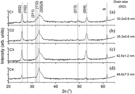
X-ray diffraction spectra of the investigated coatings deposited on Si substrates are presented in Fig. 1. According to International Centre for Diffraction Data (ICDD) file 9-0432, the C1–C4 samples' diffractograms revealed the presence of the HAP crystalline structure. For the C1 sample, the detected peaks are observed at 25.83°, 28.02°, 31.47°, 32.11°, 49.36°, and 53.15° corresponding to the (002), (102), (211), (112), (213) and (004) planes.


image file: c6ra03397k-f1.tif
Fig. 1 X-ray diffraction patterns of: (a) C1, (b) C2, (c) C3, and (d) C4 coatings deposited on Si substrates. The HAP identification according to the ICDD 9-0432 standard. “S” = peaks of the substrate. The (300) plane of HAP overlaps a peak of the substrate.

By adding the Ti to the composition of the C2–C4 samples, only the (002) and (004) reflections are observed, suggesting a preferential (00l) orientation, and the peaks are shifted to lower 2θ angles relative to the same reflection in the C1 sample. The shift is augmented with an increase in the RF power applied to the TiO2 cathode, i.e., with the increase of the Ti content in the films.

3.2. Cross-sectional morphology and the wettability studies

Atomic force microscopy was performed on the coatings deposited on silicon wafers to investigate the coating's morphology without any influence of the titanium alloy roughness (Fig. 2). As shown in the AFM images, the surfaces of C1, C2 and C3 coatings appear dense and feature dome-shaped grains. In the case of C2 and C3, the diameters of the grains were augmented with an increasing amount of titanium. For the C4 surface, some dome-shaped grains were formed. For the C1, C2 and C3, interconnected pores between the coating grains were observed, and the number of pores decreased with increasing RF power on the TiO2 target.
image file: c6ra03397k-f2.tif
Fig. 2 AFM images of the coatings deposited on Si substrates.

The roughness parameters of the uncoated and coated Ti alloy substrates are summarized in Table 3. For comparison, the results of HAP without Ti (C1 sample) are also presented. The C3 sample showed the highest root-mean-square deviation of the surface (43 nm). The Ti addition increases the roughness of the HAP coatings. The increase in target power leads to an increase in the surface roughness of the C2–C4 coatings. The Ra values of C2–C4 samples, as well as those for Rq, increased steeply with the power fed on the TiO2 cathode (from 10 W to 25 W). By increasing the RF power, the Ti content of the films is augmented, leading to the increase in roughness. By increasing the RF power, the deposition rate increased, resulting in an increase of the atomic flux. Therefore, the average distance that allows the adatoms to bond with other adatoms and form the coating was decreased by forming islands, which led to the increase in roughness.

Table 3 Roughness parameters of the investigated coatings
Coating Ra (nm) Rq (nm) Sskw
Ti6Al4V 39 ± 1.81 51 ± 2.87 0.41 ± 0.12
C1 24 ± 0.09 30 ± 0.41 −0.105 ± 0.09
C2 21 ± 0.67 26 ± 0.77 −0.005 ± 0.11
C3 26 ± 0.43 34 ± 1.09 −0.191 ± 0.34
C4 32 ± 0.21 43 ± 0.38 0.235 ± 0.18


Wang and Zreiqat have demonstrated that a high roughness means a large contact area between body fluid and the implant surface and provides more nucleation sites with a lower interfacial energy for bone-like apatite to anchor to.39 Moreover, the surface with high roughness results in an increased Ca and P release, being an advantage for bone regeneration and remodelling.39,40 Based on their results, it can be concluded that the coatings with high Ti content can be more favourable for cell adherence.

The skewness (Sskw) is sensitive to deep valleys or high peaks. According to the ISO 4287/1997 standard, surfaces with a positive skewness present relatively high spikes that protrude above a flattered average. While porous surfaces have a negative skewness, with deep valleys in a smoother plateau. Polished surfaces should exhibit a skewness of approximately zero. Sedlaček et al. have reported that the surfaces with more negative values of the Sskw parameter often present an advantage in terms of friction, as the use of surfaces with a more negative skewness always results in lower friction coefficients.41 The C2 coating has an Sskw close to zero, indicating a flat surface. An important increase in the Sskw parameter was observed for the C4 sample, indicating the presence of high spikes.

Typical cross-sectional SEM micrographs of all of the investigated coatings deposited on silicon wafers are shown in Fig. 3. The undoped HAP coating presents a columnar structure. All of the doped coatings exhibit an amorphous structure. No significant differences were found between the coatings with differing amounts of Ti added. In addition, all of the coatings were well attached to the substrate, without gaps and with uniform thicknesses.


image file: c6ra03397k-f3.tif
Fig. 3 SEM cross-sectional view of all of the coatings.

The wettability is an important property of biomaterials because the adhesion, spreading and differentiation of cells are generally better on hydrophilic surfaces.42,43 It has been reported that when functionalized with an oxygen plasma, a surface revealed increased surface energy and wettability.44 The surface energies and hence the contact angles are also influenced by factors such as surface roughness, surface chemistry and surface phases.45 Fig. 4 shows the variations of the water contact angle and the contact angle hysteresis for the uncoated and coated titanium surfaces. The corresponding water droplet shapes on the uncoated and coated surfaces were also shown. A summary of the obtained results on the total solid surface free energy, including dispersive and polar contributions, is given in Table 4.


image file: c6ra03397k-f4.tif
Fig. 4 The water contact angle (a) and contact angle hysteresis (b) measurements for the uncoated Ti and hydrophobic Ti-doped HA coatings. The inset images of (a) and (b) show the water drop shape on the respective surfaces.
Table 4 Calculated surface free energies of the uncoated and coated surfaces, including dispersive and polar contributions
Sample Surface free energy, (mH × m−1)
Dispersive Polar Total
Ti6Al4V 22.1 9.2 31.3
C1 24.5 1.2 25.7
C2 22.9 1.4 24.3
C3 23.9 0.9 24.8
C4 24.5 0.5 25.0


We see from Table 4 that the water surface contact angle for the uncoated substrate is approximately 80°; while for the coated samples, the water contact angle was found to be in the range between 97° and 102°. All of the coatings exhibited a contact angle greater than 90°, indicating a hydrophobic surface. Comparing the coatings, the increase in the RF power on the TiO2 target led to a slight increase in the contact angle. For the C2 and C3 coatings, the increase of the water contact angle is connected with the increase of the surface roughness as a result of the coating deposition. The increase of the water contact angle with the coating deposition can be connected to the process of surface nanopatterning, which prevents droplets from spreading. Moreover, for the coated surfaces, the asperities were placed close enough so that the droplets are stable. It is known that the contact angle is influenced by the surface roughness. The most simple model to explain the relation between the contact angle and roughness is the Wenzel model,46 assuming that the liquid totally fills the grooves of the rough surface. Moreover, the Wenzel theory shows that the surface roughness increases the contact angle in case of smooth surfaces with a contact angle greater than 90°, but the opposite is true when the contact angle is lower than 90°.

The uncoated substrate and HAP without Ti exhibited positive skewness indicating tall spikes on the surfaces. According to the Wenzel model, the liquid fills these grooves, and the contact angle will decrease. By increasing the RF power on the TiO2 target, the roughness increases, and the skewness approaches a zero value. This indicates an increase in the surface area of the solid, which geometrically enhances hydrophobicity (Wenzel model). Comparing the coatings, the C4 sample has a rough surface and tall spikes, which leads to an increase in the contact angle. Comparing our experimental data, we can observe that the contact angle of the coated samples augments with increasing surface roughness, being in agreement with the results reported earlier by other authors, who claim that with increasing surface roughness, the apparent contact angle increases for hydrophobic materials.47 The coating deposition process resulted in a decrease of the surface free energy from 31.3 to 24.3 mH m−1, which resulted in a significant decrease of the polar part of the surface energy. Baier et al. have correlated the surface energies of the solids with their biological interactions and agreed that the materials with an energy ranging from 20 to 30 dynes cm−1 exhibited a good biocompatibility, while those with a surface energy above 40 dynes cm−1 had a good bioadhesion.48 An increase in the water contact hysteresis from 60° to 77° was observed because of the coating's fabrication process. This increase signifies an increase in the surface wettability, which is in agreement with the decrease of the surface roughness in the case of the uncoated substrates. The results of the present study are promising because the water angle hysteresis in the case of the coated substrates is higher than those of the uncoated ones. It is known that the closer the water hysteresis is to zero, the more hydrophobic the surfaces are.49 Furthermore, taking into account both the increase of the water contact angle and the water angle hysteresis in the case of the coated substrates compared with the uncoated ones, we suggest that the wetting behaviour of the surface can be explained using a so-called Wenzel model.46

3.3. Corrosion resistance

Potentiodynamic polarization curves for the uncoated and coated Ti6Al4V alloy are presented in Fig. 5. The electrochemical parameters, i.e., the corrosion potential (Ei=0), corrosion current density (icorr) and polarization resistance (Rp), obtained from the curves are listed in Table 5. Compared with the uncoated Ti6Al4V alloy, all of the coated samples showed a shift of the corrosion potential to more electropositive values, indicating an improved corrosion resistance of the coated Ti6Al4V alloy. Compared with the HAP reference coating, significant improvements in Ei=0 were observed after the Ti addition.
image file: c6ra03397k-f5.tif
Fig. 5 Potentiodynamic curves of all of the investigated samples in the SBF solution at 37 °C.
Table 5 Electrochemical parameters of the Ti6Al4V substrate and the coatings: corrosion potential (Ei=0), corrosion current density (icorr), polarization resistance (Rp), porosity (P), and protective efficiency (Pe)
Sample Ei=0 (mV) icorr (nA cm−2) Rp (MΩ) P Pe (%)
Ti6Al4V −569 26.29 2.842
C1 −493 114.72 0.6804 2.319
C2 −379 123.45 0.4365 5.297
C3 −189 1.926 74.867 0.025 92.7
C4 −102 0.4922 215.99 0.0079 98.2


The low TiO2 target power (10 W) does not enhance the corrosion current density (icorr). With an increase in the TiO2 target power from 10 W to 17 W and from 17 W to 25 W, the corrosion current density decreases gradually. The polarization resistance of the coatings increases with the Ti addition and also with the RF power. Based on the presented results, increasing the power applied to the TiO2 cathode leads to a significant decrease in the corrosion current density and an increase in the polarization resistance, proving that the coatings prepared at a higher RF power were more resistant to corrosive attack in the SBF solution.

It is well-known that an electropositive corrosion potential, a low corrosion current density and a high polarization resistance indicate a good corrosion resistance [ASTM G 5–94]. With these criteria taken into account, we can see that the Ti addition improves the corrosion resistance of the HAP coatings. The best corrosion resistance was found for the C4 coating.

The corrosion behaviour is sensitive to structural defects, which appeared on the surfaces during the deposition. Most of these defects influenced the porosity (P) of the surfaces. Elsener et al. have shown that the surfaces are more resistant to the corrosive attack if their porosities are low.37 The HAP coatings with Ti prepared at 17 W and 25 W exhibited low porosity, demonstrating the beneficial effect of the Ti addition in the HAP structure. Comparing the HAP coatings with the Ti addition, the protective efficiency (Pe) of the coatings was augmented with increasing RF power on the TiO2 target. The results showed that the C4 coating showed the highest Pe value.

After the electrochemical tests in SBF solutions at 37 °C, XRD and SEM/EDS investigations were carried out for all of the coatings. For the uncoated Ti6Al4V alloy, XRD shows only the corresponding peaks of the Ti alloy, without any traces of oxides on the surface. It is possible that some oxides exist on the surface, but these are extremely thin, being undetectable by XRD. For all of the coatings, the XRD indicates the presence of the Ti6Al4V peaks, showing that the films were partially dissolved. For the C4 coating, the presence of hydroxyapatite is detected (Fig. 6), meaning the initial HAP layer was partially dissolved. This shows that this coating was resistant to the corrosive attack of the SBF. The XRD results are also supported by the SEM/EDS analysis (Fig. 7). The SEM images show that the C1, C2 and C4 coatings were partially dissolved, and in some parts of the surface, an apatite layer formed. For the C3 coating, the area without coating is bigger than it is in other samples, indicating a high dissolution rate of the coating.


image file: c6ra03397k-f6.tif
Fig. 6 X-ray diffraction patterns of the uncoated Ti6Al4V alloy and the C4 coating after the electrochemical tests.

image file: c6ra03397k-f7.tif
Fig. 7 SEM images of the coated samples after the electrochemical tests in SBF at 37 °C.

3.4. Analysis of the corrosion mechanisms

Zhang and co-authors showed that the corrosion mechanism of the HAP coating involves two steps: the production of hydrogen ions (H+) and the dissolution of HAP in the high H+ concentration.50 Thus, the main degradation mechanism of the investigated coatings is dissolution. This conclusion is also supported by the XRD and EDS results. Most likely, the H+ ions decrease the local pH at the sample–solution interface, leading to the high dissolution of the HAP coatings. This process is very intense, and it cannot be stopped until the coating is dissolved. After the immersion in SBF, on the sample surfaces, some amorphous calcium phosphate particles formed. However, the dissolution of the deposited HAP coating does not stop. Usually, the dissolution process is more rapid than the formation of a new CaP layer. This result is in good agreement with the ref. 51. The dissolution process of the deposited HAP coating is quite complex and there are many factors that affect it. To understand what influences the HAP dissolution, it is first important to closely examine the porosity and the protective efficiency of the coatings.

The porosity of the coatings can be explained by considering the results of the electrochemical tests. The differences in the porosity were due to the presence of the pinholes produced during the deposition process. By increasing the power applied to the TiO2 target, the pinholes were reduced, and consequently, the actual solid surface area and the electrolyte diffusion, through the open porosity to the substrate, decreased. The chloride ions (Cl) penetrate the pores or other defects, and the substrate area exposed to the corrosive attack will be much larger, leading to an increase of the corrosion rate. Our results are in agreement with those of Creus et al. who have noted that the corrosive attack of a surface with pores or other defects is more active because the cathode area is much larger than the anodic area, and the surface ratio, in direct contact with the corrosive solution, increased (cathodic surface ≫ anodic surface).52 The AFM results and the investigation into the surface wettability support the degradation mechanism of the HAP coatings. The AFM images revealed the interconnected pores between the coating grains, and we can see that the number of pores decreased by increasing the RF power on the TiO2 target. Based on these results, the C4 coating showed a compact coating with small pores in which the SBF solution can penetrate, leading to better corrosion behaviour. It is reported that the grain boundaries significantly facilitate the localized dissolution of a material.53

The surface wettability and thus the tendency of water droplets to wet the surface were evaluated by measuring the contact angle and hysteresis values for different surface compositions, as well as different surface roughnesses. It was found that the hydrophobic coated titanium surface is simultaneously strongly adhesive to water. The Wenzel's state denotes a wetting contact mode, where water droplets are pinned on a surface to form a high contact angle hysteresis. It can be concluded that there is an interaction force between the fluid and the coated titanium surface.

Thus, the deposited coating can control the penetration of aggressive ions attacking the surface. In the case of the uncoated titanium substrate, the attack by the chloride ions is substantially stronger because there is no barrier influence of the pure HAP and Ti-doped HAP films. The fabrication of relatively compact Ti-doped HAP coating could help to effectively reduce the direct contact between the titanium surface and the electrolyte.

4. Conclusions

The HAP coatings with the addition of Ti were prepared on the Ti6Al4V alloy substrates at different RF powers applied to the TiO2 target for biomedical applications.

Important results are summarized as follows:

• The titanium content was augmented by increasing the RF power.

• The roughness of the coatings was increased considerably at a higher RF power.

• Comparing the coatings, the increase in the RF power on the TiO2 target led to a slight increase in the contact angle.

• The decreased surface roughness of the coatings resulted in a complete surface wetting.

• All of the Ti-enriched HAP coatings were found to enhance the corrosion resistance of the Ti6Al4V alloy in the SBF solution. The best corrosion resistance was found for the coatings deposited at a high RF power (25 W), which proved to have a low porosity (0.0079) and a high protective efficiency to corrosive attack (98.2%). For this coating, the low corrosion current density was determined, indicating a low dissolution rate. In this study, the assumption of dissolution as the main degradation mechanism of pure and Ti-doped HAP coatings deposited on titanium alloy is challenged.

Based on these results, the incorporation of Ti into the structure of HAP could be a promising way to prepare an implant for bone substitution.

Acknowledgements

The work was supported by the grants of the Romanian National Authority for Scientific Research and Innovation, CCCDI – UEFISCDI, Project numbers PN-II-PT-PCCA-2014-212, 44/2016 and 43/2016 – INTELBIOCOMP, within PNCDI III and by the Federal Target Program #14.587.21.0013 (a unique application number 2015-14-588-0002-5599), the Russian President's grant МК-7907.2016.8. The cross-section images were acquired using a scanning electron microscope with field emission (FEI QUANTA 450 FEG) purchased by the Sectorial Operational Programme “Increase of economic Competitiveness”, ID 1799/SMIS 48589/2015.

References

  1. C. Leyens and M. Peters, Titanium and Titanium Alloys, WILEY-VCH Verlag GmbH & Co., Weinheim, 2003 Search PubMed.
  2. S. Bauer, P. Schmuki, K. von der Mark and J. Park, Prog. Mater. Sci., 2012, 58, 261–326 CrossRef.
  3. C. O. Dominguez and A. Dominguez, in Recent Advances in Arthroplasty, ed. D. S. Fokter, InTech, 2012, pp. 149–162 Search PubMed.
  4. J. Duyck and I. Naert, Clin. Oral Investig., 1998, 2, 102–114 CrossRef CAS PubMed.
  5. S. Amin Yavari, S. M. Ahmadi, J. van der Stok, R. Wauthle, A. C. Riemslag, M. Janssen, J. Schrooten, H. Weinans and A. A. Zadpoor, J. Mech. Behav. Biomed. Mater., 2014, 36, 109–119 CrossRef CAS PubMed.
  6. Y. Torres, P. Trueba, J. Pavón, I. Montealegre and J. A. Rodríguez-Ortiz, Mater. Des., 2014, 63, 316–324 CrossRef CAS.
  7. M. Gasik, A. Braem, A. Chaudhari, J. Duyck and J. Vleugels, Mater. Sci. Eng., C, 2015, 49, 152–158 CrossRef CAS PubMed.
  8. Y. Qiao and X. Liu, in Comprehensive Materials Processing, 2014, vol. 4, pp. 425–447 Search PubMed.
  9. R. S. Pessoa, M. A. Fraga, L. V. Santos, N. K. A. M. Galvão, H. S. Maciel and M. Massi, in Anti-Abrasive Nanocoatings: Current and Future Applications, Elsevier Ltd., 2014, pp. 456–479 Search PubMed.
  10. M. Yaseen, B. J. Cowsill and J. R. Lu, in Coatings for Biomedical Applications, Woodhead Publishing, 2012, pp. 176–220 Search PubMed.
  11. D. R. Sumner and S. Amarjit, in Surgery of the Hip, ed. D. J. Berry, Saunders, United States, 2013, pp. 145–156 Search PubMed.
  12. R. S. Corpe, D. E. Steflik, R. Y. Whitehead, M. D. Wilson, T. R. Young and C. Jaramillo, Crit. Rev. Biomed. Eng., 2000, 28, 395–398 CrossRef CAS PubMed.
  13. J. C. Elliott, Structure and chemistry of the apatites and other calcium orthophosphates, Elsevier Ltd, 1994, vol. 18 Search PubMed.
  14. R. A. Surmenev, M. A. Surmeneva and A. A. Ivanova, Acta Biomater., 2014, 10, 557–579 CrossRef CAS PubMed.
  15. S. J. Ding, Biomaterials, 2003, 24, 4233–4238 CrossRef CAS PubMed.
  16. P. Li, K. de Groot and T. Kokubo, J. Sol-Gel Sci. Technol., 1996, 7, 27–34 CrossRef CAS.
  17. Y. Han, T. Fu, J. Lu and K. Xu, J. Biomed. Mater. Res., 2001, 54, 96–101 CrossRef CAS PubMed.
  18. M. Yoshinari, Y. Ohtsuka and T. Derand, Biomaterials, 1994, 15, 529–535 CrossRef CAS PubMed.
  19. P. Habibovic and F. Barrere, J. Am. Ceram. Soc., 2002, 85, 517–522 CrossRef CAS.
  20. N. J. Hallab, J. J. Jacobs and J. L. Gilbert, in Joint Replacement and Bone Resorption: Pathology, Biomaterials and Clinical Practice, ed. A. Shanbhag, H. E. Rubash and J. J. Jacobs, CRC Press, 1st edn, 2005, pp. 211–254 Search PubMed.
  21. Y. Han, K. Xu and J. Lu, J. Mater. Sci.: Mater. Med., 1999, 10, 243–248 CrossRef CAS PubMed.
  22. V. B. Damodaran, D. Bhatnagar, V. Leszczak and K. C. Popat, RSC Adv., 2015, 5, 37149–37171 RSC.
  23. A. R. Boyd, L. Rutledge, L. D. Randolph, I. Mutreja and B. J. Meenan, J. Mater. Sci.: Mater. Med., 2015, 26, 65 CrossRef PubMed.
  24. E. S. Thian, J. Huang, S. M. Best, Z. H. Barber and W. Bonfield, J. Biomed. Mater. Res., Part B, 2006, 76, 326–333 CrossRef CAS PubMed.
  25. A. Y. Desai, Masters thesis, University of Cambridge, 2007.
  26. B.-H. Lee and N. Koshizaki, Nanotechnology, 2008, 19, 415303 CrossRef PubMed.
  27. Y. X. Leng, J. Chen, J. Wang, G. J. Wan, H. Sun, P. Yang and N. Huang, Surf. Coat. Technol., 2006, 201, 157–163 CrossRef CAS.
  28. X. Zhao, Bioact. Mater. Med., 2011, 97–123 Search PubMed.
  29. Y. Tian, H. Cao, Y. Qiao, F. Meng and X. Liu, Acta Biomater., 2014, 10, 4505–4517 CrossRef CAS PubMed.
  30. O. Anderson, C. H. Ottermann, R. Kuschnereit, P. Hess and K. Bange, Fresenius. J. Anal. Chem., 1997, 358, 315–318 CrossRef CAS.
  31. M. Zheng, M. Sakairi and H. Jha, Corros. Sci., 2012, 55, 332–338 CrossRef CAS.
  32. K. Liu and L. Jiang, Nanoscale, 2011, 3, 825–838 RSC.
  33. A. Vladescu, M. Braic, F. A. Azem, I. Titorencu, V. Braic, V. Pruna, A. Kiss, A. C. Parau and I. Birlik, Appl. Surf. Sci., 2015, 354, 373–379 CrossRef CAS.
  34. T. Wong, T. Sun, L. Feng and J. Aizenberg, Mater. Res. Soc. Bull., 2013, 38, 366–371 CrossRef CAS.
  35. H. B. Eral, D. J. C. M. 'T Mannetje and J. M. Oh, Colloid Polym. Sci., 2013, 291, 247–260 CAS.
  36. A. K. Kota, W. Choi and A. Tuteja, MRS Bull., 2013, 38, 383–390 CrossRef CAS.
  37. B. Elsener, A. Rota and H. Böhni, Mater. Sci. Forum, 1989, 44/45, 29–38 CrossRef.
  38. K. Nozawa and K. Aramaki, Corros. Sci., 1999, 41, 57–73 CrossRef CAS.
  39. G. Wang and H. Zreiqat, Materials, 2010, 3, 3994–4050 CrossRef CAS.
  40. S. Parithimarkalaignan and T. V. Padmanabhan, Journal of Indian Prosthodontic Society, 2013, 13, 2–6 CrossRef CAS PubMed.
  41. M. Sedlaček, L. M. S. Vilhena, B. Podgornik and J. Vižintin, Strojniški vestnik–Journal of Mechanical Engineering, 2011, 57, 674–680 CrossRef.
  42. H. Liao, A. S. Andersson, D. Sutherland, S. Petronis, B. Kasemo and P. Thomsen, Biomaterials, 2003, 24, 649–654 CrossRef CAS PubMed.
  43. C. Ma, A. Nagai, Y. Yamazaki, T. Toyama, Y. Tsutsumi, T. Hanawa, W. Wang and K. Yamashita, Acta Biomater., 2012, 8, 860–865 CrossRef CAS PubMed.
  44. U. Cvelbar, M. Modic, J. Kovac, S. Lazovic, G. Filipic, D. Vujosevic, I. Junkar, K. Elersic, S. P. Bruhi, C. Canal, T. Belmonte and M. Mozetic, Surf. Coat. Technol., 2012, 211, 200–204 CrossRef CAS.
  45. A. K. Kurella, M. Z. Hu and N. B. Dahotre, Mater. Sci. Eng., C, 2008, 28, 1560–1564 CrossRef CAS.
  46. R. N. Wenzel, J. Ind. Eng. Chem., 1936, 28, 988–994 CrossRef CAS.
  47. T. T. Chau, W. J. Bruckard, P. T. L. Koh and A. V. Nguyen, Adv. Colloid Interface Sci., 2009, 150, 106–115 CrossRef CAS PubMed.
  48. R. E. Baier and V. A. DePalma, in Management of Arterial Occlusive Disease, ed. W. Dale, Year Book Medical Publishers, Chicago, 1971, pp. 147–163 Search PubMed.
  49. M. Liu, S. Wang and L. Jiang, Mater. Res. Bull., 2013, 38, 375–382 CrossRef CAS.
  50. Z. Zhang, M. F. Dunn, T. D. Xiao, A. P. Tomsia and E. Saiz, in MRS Proceedings, 2001, p. 703 Search PubMed.
  51. L. Verestiuc, C. Morosanu, M. Bercu, I. Pasuk and I. N. Mihailescu, J. Cryst. Growth, 2004, 264, 483–491 CrossRef CAS.
  52. J. Creus, H. Mazille and H. Idrissi, Surf. Coat. Technol., 2000, 130, 224–232 CrossRef CAS.
  53. D. López, C. Sánchez and A. Toro, in Wear, 2005, vol. 258, pp. 684–692 Search PubMed.

This journal is © The Royal Society of Chemistry 2016