
 Open Access Article
 This Open Access Article is licensed under a
 Creative Commons Attribution 3.0 Unported Licence
Electrocatalytic regeneration of atmospherically aged MoS2 nanostructures via solution-phase sulfidation†
H. A. Burchab,
M. Isaacsc,
K. Wilsonc,
R. E. Palmerb and
N. V. Rees*a
aSchool of Chemical Engineering, University of Birmingham, UK. E-mail: N.Rees@Bham.ac.uk
bNanoscale Physics Research Laboratory (NPRL), University of Birmingham, UK
cEuropean Bioenergy Research Institute (EBRI), Aston University, UK
First published on 4th March 2016
Abstract
The performance of MoS2 as a hydrogen evolution catalyst is diminished by exposure to air. We demonstrate a solution phase technique to resulfidate MoSxO2−x using Na2S2O3. The success of the method was judged by performance as a H+ reduction catalyst. Following sulfidation samples displayed a favourable decrease in both onset potential and Tafel slope, with the best decreasing from −0.23 V to −0.18 V (vs. SHE), and 282 mV dec−1 to 87 mV dec−1 respectively. Ageing studies indicate that this method may be used to recycle the MoS2 repeatedly without losing catalytic performance, although repeated sulfidation did result in homogenisation of the nanostructure.
Introduction
MoS2 is an earth abundant, 2D-layered transition metal dichalcogenide (TMD) which is already deployed in hydrodesulfurisation catalysis,1,2 electrocatalysis,3,4 and shows potential for photoelectrocatalysis (PEC).5,6 One application is the photoelectrocatalytic hydrogen evolution reaction (HER).| 2H+(aq) + 2e− ⇌ H2(g) | (1) |
This in conjunction with the oxygen evolution reaction (OER) (eqn (2)) comprises photoelectrocatalytic water splitting.7
| H2O + 2h+ ⇌ 0.5O2(g) + 2H+(aq) | (2) |
In order for spontaneous light driven water splitting to proceed the free-energy stored in the photogenerated electron–holes pairs must exceed the energy separation between the H+/H2 and O2/H2O redox energy levels (1.23 V at 298 K).8 In practice an overpotential is also required to drive the separation of charge carriers.8 This can be achieved either by one material which straddles the water splitting redox energy levels, or two or more materials with overlapping bandgaps connected in tandem.9 MoS2 meets the requirements for PEC HER as it is catalytically active for HER, and absorbs sufficient light to generate an electron–hole pair with enough potential to drive the HER.10 The free energy level of the conduction band is also negative of the reduction potential of H+/H2.8,11 Nanopatterning is common technique used to adapt the band gap, as well as increasing the number of active edge sites.10 Various nanostructuring techniques have been applied to attempt to improve the catalytic properties of MoS2 including: electrodeposition,3 cluster deposition,12 sonochemical synthesis,13 chemical vapour deposition,14 and chemical exfoliation.15
The basal plane of MoS2 is inert for the HER, while the (10![[1 with combining macron]](https://www.rsc.org/images/entities/char_0031_0304.gif) 0) edge sites are catalytically active.5,16 The initial step of the HER is the binding of hydrogen to sulfur atoms on the Mo-edge (100),5 however these edge sites adsorb oxygen at room temperature.17 Due to this poor stability is an issue with MoS2 electrocatalysis, although long term performance has not been studied in depth.18
0) edge sites are catalytically active.5,16 The initial step of the HER is the binding of hydrogen to sulfur atoms on the Mo-edge (100),5 however these edge sites adsorb oxygen at room temperature.17 Due to this poor stability is an issue with MoS2 electrocatalysis, although long term performance has not been studied in depth.18
Little attention has been paid to restoring the functionality of MoS2 partially oxidised to MoSxO(2−x) in air. To address this issue nanopatterned MoS2 was prepared using nanosphere lithography and plasma etching19,20 in order to produce a larger number of catalytically active edge sites, these sites were then allowed to oxidise in air before regeneration. In this paper we present a rapid, room temperature, solution-phase method to sulfidise air-exposed MoS2 through electrochemical deposition of sulfur from a sodium thiosulfate solution. Although MoS2 has been synthesised in the solution phase using Na2S2O3 and a Mo ion source,21 this technique has not been applied to restoring the functionality of air-exposed MoS2, nor has MoS2 synthesised via this method been investigated for HER.22 This method avoids the use of toxic chemicals such as H2S, Na2S, or vapourised sulfur at high temperature employed in many current methods to synthesise MoS2 from MoOx.23–26 The sulfidation process was analysed physically through SEM and XPS, and electrochemically via the electrochemical reduction of protons on the air-exposed MoS2 before and after sulfidation. The electrode surfaces before and after sulfur deposition have been imaged by SEM, and the chemical composition confirmed by XPS.
It was found that the sulfidation results in an increase in MoS2 composition from 49.5% to 58%. This increase in MoS2 composition had a beneficial effect on the cyclic voltammetry of the sample, resulting in a lower overpotential for the HER as evidenced by the decrease in onset potential from −0.23 V SHE to −0.18 V, plus a decrease in the Tafel slope from 282 mV dec−1 to 87 mV dec−1. For comparison a freshly nanopatterned MoS2 was found to have an onset potential of −0.2 V SHE, and a Tafel slope of 120 mV dec−1. Ageing studies found that when left exposed to air for 21 days following sulfidation HER performance steadily decreases, but can be reinstated by further sulfidation.
Results and discussion
Nanostructuring and sulfidation
The structuring by nanosphere lithography and plasma etching is covered briefly here.19,20 First, naturally occurring MoS2 crystals were mounted onto a GC substrate, cleaved between basal planes, then placed at the bottom of a beaker of water. Polystyrene nanospheres were deposited from a suspension in ethanol onto the surface of the water, forming a self-assembled monolayer. The water level was lowered using a syringe until the nanospheres deposited onto the MoS2. The nanospheres were then exposed to oxygen plasma at 100 SCCM (standard cubic centimetres per minute) for 30 to 50 seconds in order to reduce their size before the MoS2 was etched with SF6 plasma at 25 SCCM for 25 to 40 seconds. After both etches the nanospheres were washed off the MoS2 with acetone, leaving a nanopatterned crystal, which was imaged by SEM. Following the nanopatterning the MoS2 samples were stored for a period of 5 to 28 days, it was found however, that the samples stored for longer than 23 days had already fully aged (Fig. S1†). For this reason the bulk and freshly fabricated samples (Fig. 2) were electrochemically tested immediately following manufacture. Following exposure to air the crystals were sulfidated electrochemically and subsequently re-tested. The methodology was inspired by strategies to synthesise MoS2 and other metal sulphides from metal ions and sodium thiosulfate.21,22,27–29The air-exposed MoS2 modified GC working electrode was placed in a solution containing 10 mM Na2S2O3, and 0.1 M Na2SO4 which has been acidified to pH 3 in order to reduce the S2O32− via28,30
| S2O32−(aq) + H+(aq) ⇌ S(s) + HSO3−(aq) | (3) |
An oxidative voltage scan was then used to fully oxidise the Mo as this has previously been found to yield MoS2 on exposure to sulfur.22,26 A reductive voltage scan was then applied (at a scan rate of 25 mV s−1) to electroreduce the colloidal sulfur onto the electrode (eqn (3)).28
| S(s) + 2e− ⇌ S2−(aq) | (4) |
Experimental results confirmed that the sulfidation gave improved voltammetric results if the electrode was swept anodically prior to the reductive deposition (Fig. S2†). The sulfidated MoS2 samples were then characterised by SEM and XPS, and the electrochemical performance as HER catalysts recorded and compared to the pre-sulfidated results.
Physical characterisation
The SEM images (Fig. 1) reveal that repeated deposition results in the filling of gaps between the pillars, which builds up over repeated sulfidations, and could explain the lowering of current as fewer catalytically active edge sites are available, provided that sufficient active sites are lost over a diffusionally-relevant area to effect a change in diffusional character of the nano-array from case IV.31 The H+ reduction measurements corresponding to each of these sulfidations are provided in Fig. S7.† However the remaining edge sites appear to have improved catalytic properties, indicating this method would be well suited to robust morphologies, or electrodes that do not require multiple re-use.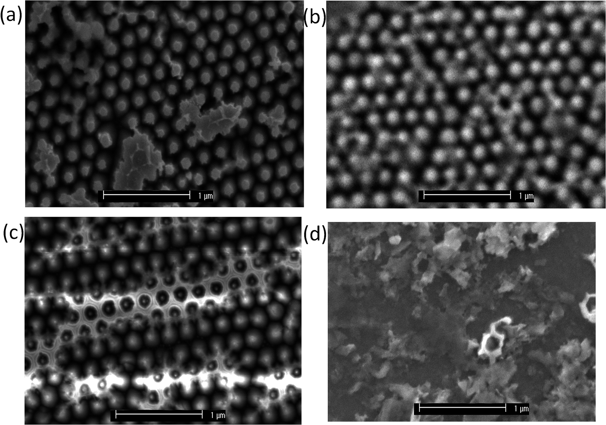 | ||
| Fig. 1 SEM images showing the effect of sulfidation on the surface of nanopatterned MoS2. (a) Sample 1 before sulfidation: the features are individual and distinct, and (b) after 2 sulfidations: the features remain distinct. (c) Sample 2 before sulfidation: the features are individual and distinct, and (d) after 8 sulfidations: the surface has homogenised though some features remain visible. | ||
Surface XPS data identified a decrease in the MoS2 content of the Mo 3d region and concurrent increase in MoO2 when the sample degraded in air, and that the sulfidation reverses this process (Table 1, Fig. S5†). MoO3, readily identified by a significant Mo 3d3/2 peaks at 235.6 eV, appears to decrease largely to the Mo(IV) species, of which sulfidation is unable to reoxidise. MoS2 is identified at a binding energy of 229 eV for the 5/2 peak, with MoO2 existing at a slightly higher binding energy of 229.7 eV. The broadening and shift to a higher energy of the major Mo 3d5/2 species could therefore be deconvoluted to probe the chemical composition. The MoS2 composition of the freshly fabricated sample was very similar to that of the sulfidated sample indicating that sulfidation did indeed regenerate the samples surface. This conclusion is corroborated by the electrochemical measurements in Fig. 3(a).
| Sample | % MoS2 | % MoO3 | % MoO2 |
|---|---|---|---|
| Freshly fabricated | 56.07 | 35.83 | 8.10 |
| Air-exposed | 45.52 | 2.51 | 51.97 |
| Sulfidated | 57.99 | 5.03 | 36.98 |
Electrochemical characterisation
The performance of the MoS2 as a H+ reduction catalyst was tested as a means of comparison (see Experimental). The electrode was immersed into a thoroughly degassed solution of 2 mM HClO4 and 0.1 M NaClO4 in ultrapure water along with a saturated Ag/AgCl reference electrode and Pt mesh counter electrode. Cyclic voltammograms were recorded from 0 V Ag/AgCl to −1.6 V at a scan rate of 25 mV s−1 (Fig. 2(a)).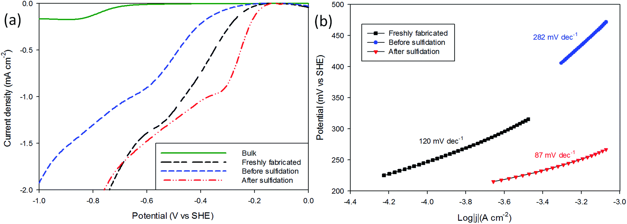 | ||
| Fig. 2 Comparison of electrocatalytic performance of freshly nanopatterned, and before and after sulfidation nanopatterned MoS2 as well as bulk MoS2 for proton reduction. The data presented here is baseline corrected, and numbers quoted in the text are adjusted to SHE and corrected for Nernstian shift. (a) i–V curves of before and after sulfidation, compared to freshly nanopatterned and bulk MoS2. (b) Tafel slopes derived from (a). | ||
It can be seen that following sulfidation the MoS2 displays improved catalysis for H+ reduction (Fig. 2(a) sulfidated) with the onset potentials, identified by where the trace departs from the baseline, changed from −0.23 V SHE in the air-exposed state to −0.18 V SHE. These values are favourable compared with bulk MoS2 (−0.65 V SHE), and the sulfidated onset is comparable to the freshly prepared sample (−0.20 V SHE). These results are in good agreement with other studies on nanostructured MoS2 HER, with an onset of ≈−0.20 V SHE commonly reported.4,32–35
The magnitude of the post-sulfidation current is intermediate to the crystals' aged state and freshly prepared state.
Tafel plots were constructed from the voltammetric results in order to measure the effect of the sulfidation on the HER kinetics. The HER in acidic media is well known to proceed via two pathways, each composed of two reaction steps.
 | (5) |
 | (6) |
 | (7) |
The first step common to both pathways is the primary discharge step (Volmer reaction, eqn (5)). What follows this is either an electrochemical desorption step (Heyrovský reaction, eqn (6)) or a recombination/desorption step (Tafel reaction, eqn (7)).
Due to the fast kinetics of the HER on Pt, it is widely considered a benchmark catalyst, and is known to proceed through the Volmer–Tafel reaction (eqn (5) and (7)).36–38
The precise pathway of hydrogen evolution on MoS2 is still unknown.37 However, MoS2 has been combined with reduced-graphene oxide (RGO), as well as single-walled carbon nanotubes to achieve Tafel slopes of ≈41 mV dec−1 (ref. 32 and 37) indicating a Volmer–Heyrovský reaction.
Various structuring techniques have been applied to optimise the performance of MoS2 in the HER. The lowest measured Tafel slope for pure MoS2 is 49 mV dec−1 and was achieved through edge termination and layer expansion.39 Other structures include nanoparticulate MoS2, 2D MoS2, and vertically aligned layers; achieving 55 mV dec−1,33 67 mV dec−1,32 and 86 mV dec−1,4 respectively. Bulk MoS2 has a slope of ≈120 mV dec−1 which suggests the primary discharge step is rate limiting.34,35,40
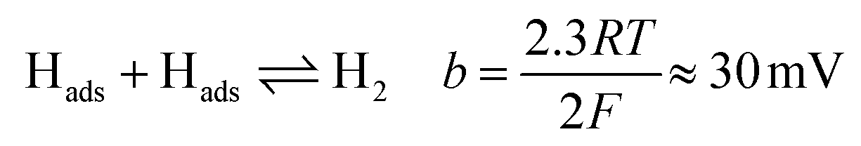
The Tafel responses obtained from the above samples showed some variation, but all displayed a decrease in Tafel slope following sulfidation. The freshly nanopatterned MoS2 from this work had a slope of 120 mV dec−1 indicating the primary discharge step (eqn (4)) was rate limiting (Fig. 2(b)) as in the case of bulk MoS2.34,35,40 When the samples were exposed to air for over 23 days the HER kinetics slowed considerably, evidenced by the increase in the Tafel slope to 282 mV dec−1. Sulfidation of the surface improved catalysis to a Tafel slope of 87 mV dec−1, comparable with other structured MoS2 reports.4,32,33 This is consistent with the restoration of catalytically active sulfur atoms on the MoS2 (100) edge enabling faster primary discharge kinetics as compared with the air-exposed state.10 Proton reduction measurements were used to record how the HER performance of the sulfidated crystals changed (Fig. 3). A sulfidated sample was left exposed to air for 2 months and voltammetrically cycled from 0 V Ag/AgCl to −1.6 V in 2 mM HClO4 solution three times over a three week period. After the three weeks the H+ reduction kinetics were still faster than in the crystals' (pre-sulfidated) air-exposed state, however both the onset potential and current were inferior to the first H+ reduction test. The Tafel slope before sulfidation was 204 mV dec−1, and decreased to 128 mV dec−1 after the deposition (Fig. S6†).
 | ||
| Fig. 3 H+ reduction tests before and after sulfidation to investigate the rate of ageing. (a) i–V curves showing the effect of sulfidation followed by gradual air-exposure and resulfidation. The sample had previously been exposed to air for two months before being H+ reduction tested and sulfidated. Following this H+ reduction was performed at regular intervals over a three week period, before re-sulfidation. The performance improved after the first sulfidation, and steadily decreased, the second sulfidation restored H+ reduction performance to roughly the same. (b) i–V curves of the ageing caused by cycling of the electrode in dilute acid. Sulfidation improved performance, but there was significant degradation between cycle 1 and 2. The sample was stable between cycle 2 and 20. | ||
The slope steadily increased with each subsequent measurement to 188 mV dec−1 after the three week period. After the final air-exposed measurement the sulfidation process was repeated and the catalytic ability remeasured. It was found that the performance was in very close agreement with the day one sulfidation, with a Tafel slope of 119 mV dec−1. This result indicates the sulfidation process can be used to repeatedly cycle air-exposed MoS2 without a permanent decrease in HER catalytic performance.
Photoelectrochemistry
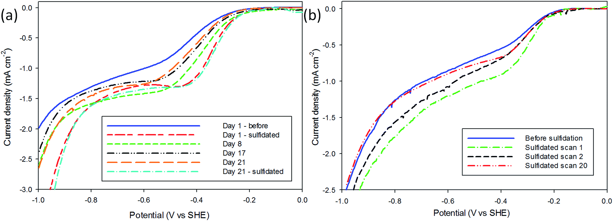
A brief investigation into the photoelectrochemical H+ reduction of both air-exposed and sulfidated MoS2 was performed under AM 1.5 (1 kW m−2) intensity from a Hg–Xe discharge lamp. The PEC measurements (Fig. 4) were performed in the same 2 mM HClO4 electrolyte, and using the same experimental procedure as above, except the electrochemical cell was fitted with a quartz window. The H+ reduction performance of three samples that had been air-exposed for longer than one month was first tested under dark, light, and interrupted conditions, before undergoing sulfidation. The same sample was then retested in dark, light and interrupted conditions, and the results shown in Fig. 4. It can be seen that the pre-sulfidation measurements showed little activity as a photocatalyst. The sulfidated sample displays a significant increase in light current as compared with dark current, the current increased tenfold compared to the pre-sulfidated sample, indicating that the sulfidation restores the photoelectrocatalytic activity of air-exposed MoS2. The onset potential moves to lower overpotentials due to illumination providing additional applied potential as a result of separating charge carriers in the sulfidated MoS2. This was not observed in the pre-sulfidated state implying that the sulfidation process has altered the material bandgap to a value more applicable for PEC HER.41,42 | ||
| Fig. 4 H+ reduction on air-exposed and sulfidated MoS2 under dark and light conditions. (a) i–V curves of air-exposed MoS2 under light, dark and interrupted light conditions. The light had a slight increase in current, however the interrupted showed peaks and troughs of only ≈0.3 μA. (b) i–V curves of sulfidated MoS2 under light, dark and interrupted conditions. Exposure to light led to an increase in current, and the difference between the peaks and troughs during the interrupted condition were ≈10 times that of the air-exposed state. | ||
Conclusion
The ageing of nanopatterned MoS2 in air is detrimental to its use as a photocatalyst for the HER. We have demonstrated a simple room temperature technique by which oxygen aged MoS2 can be restored to functionality. XPS data was used to verify the change in composition when MoS2 is left exposed to air, and that the sulfidation technique proposed here causes a reversal. H+ reduction was used to measure the success of the method, it was found that both onset potential and current were improved post-sulfidation as compared with an air-exposed sample.Tafel slopes varied from sample to sample, but sulfidation always resulted in a decrease. The lowest Tafel slope for sulfidated MoS2 was 87 mV dec−1, indicating a substantially faster HER kinetics than the oxygen-aged state (282 mV dec−1). Once sulfidated the MoS2 was found to age in air once more, however by repeating the sulfidation process catalytic performance was restored without loss in performance, enabling the same electrode to be recycled. The sulfidated electrodes also aged between the first and second H+ reduction i–V scans, but were then stable for at least 20 scans. Photoelectrochemical H+ reduction under AM 1.5 (1 kW m−2) demonstrated that the air-exposed electrodes have very little photocatalytic performance, while once sulfidated there is a significant increase in both current and onset potential in light over dark conditions.
Experimental
Naturally occurring MoS2 (99% purity, SPI Supplies Ltd) was adhered to a glassy carbon (GC) substrate (Alfa Aesar Ltd, 5 mm dia., type 2) using conductive double sided carbon adhesive tape (SPI Supplies Ltd) and cleaved between basal planes to present a flat surface (Fig. S8†). The GC was then coated with epoxy resin (Permatex quick set epoxy glue) leaving only the MoS2 exposed for use as the working electrode. Nanosphere solution (0.22 μm, Thermo Scientific Microparticle Technology) was deposited on the surface, and the nanospheres shrunk and MoS2 etched with an Oxford Instruments PlasmaPro NGP80 etcher. The geometric area of the MoS2 was measured using a Zeiss Lab A1 optical microscope. Images were recorded using a MicroPublisher 3.3 RTV camera. The geometric area of the MoS2 was calculated by Klonk image measurement software.All electrochemical measurements were performed in a three-electrode electrochemical cell using a PGSTAT128N potentiostat (Metrohm Autolab BV, Utrecht, NL) under a nitrogen atmosphere. The proton reduction experiments were performed in 2 mM perchloric acid (70%, Sigma-Aldrich) electrolyte with 0.1 M sodium perchlorate (98%, Sigma-Aldrich) supporting electrolyte prepared in ultra pure water (MilliQ by Millipore, with resistivity ≥18 MΩ cm) and thoroughly purged with N2 gas to remove dissolved oxygen. A silver–silver-chloride electrode (saturated KCl) (Sigma-Aldrich) and a bright Pt mesh were used as reference and counter electrodes, respectively. The potential vs. SHE was calculated using the following equation:26
| ESHE = Emeasured + E0Ag/AgCl + (0.059 × pH) |
The sulfidation of MoS2 crystals was carried out in a solution of 10 mM sodium thiosulfate (99%, Sigma-Aldrich), 1 mM sulfuric acid (98%, Sigma-Aldrich), with 0.1 M sodium sulfate (99% Sigma-Aldrich) supporting electrolyte prepared in ultra pure water purged with N2 gas. A double-junction Ag/AgCl (3 M KCl) electrode (Sigma-Aldrich) was used as a reference electrode to prevent interference from sulphide ions.43 The counter electrode was a bright Pt mesh.
PEC measurements were made using an electrochemical cell equipped with a quartz window, and a Lot-Oriel Hg–Xe lamp calibrated to 1000 W m−2 (AM 1.5) light source. The graphs for EC and PEC measurements are presented as recorded baseline correction, whereas the values in the text have been adjusted against SHE and corrected for Nernstian shift in order to aid comparison with other published values, and to account for the low concentration of electrolyte used in this study for the purpose of removing the effects of migration from the electrochemical results.
An XL 20 SFEG Scanning Electron Microscope (FEI) was used to image the surfaces.
XPS spectra were acquired using a Kratos Axis HSi XP spectrophotometer equipped with a charge neutraliser and a magnesium Kα source (1253.7 eV). Spectra were recorded at normal emission using a pass energy of 160 for survey scans and 20 for high resolution scans under a vacuum of 10−10 Torr. Curve fitting was performed using CasaXPS software version 2.3.16 and energy calibrated to the adventitious carbon 1s peak at 284.6 eV, employing Gaussian–Lorentz peak shapes and a Shirley background.
Acknowledgements
This work was funded by the Engineering and Physical Sciences Research Council (EPSRC).References
- R. Chianelli, J. Catal., 1984, 86, 226–230 CrossRef CAS.
- N. Liu, X. Wang, W. Xu, H. Hu, J. Liang and J. Qiu, Fuel, 2014, 119, 163–169 CrossRef CAS.
- J. Kibsgaard, Z. Chen, B. N. Reinecke and T. F. Jaramillo, Nat. Mater., 2012, 11, 963–969 CrossRef CAS PubMed.
- D. Kong, H. Wang, J. J. Cha, M. Pasta, K. J. Koski, J. Yao and Y. Cui, Nano Lett., 2013, 13, 1341–1347 CrossRef CAS PubMed.
- Y. Huang, R. J. Nielsen, W. A. Goddard and M. P. Soriaga, J. Am. Chem. Soc., 2015, 137, 6692–6698 CrossRef CAS PubMed.
- S. Shin, Z. Jin, D. H. Kwon, R. Bose and Y. S. Min, Langmuir, 2015, 31, 1196–1202 CrossRef CAS PubMed.
- M. G. Walter, E. L. Warren, J. R. McKone, S. W. Boettcher, Q. Mi, E. A. Santori and N. S. Lewis, Chem. Rev., 2010, 110, 6446–6473 CrossRef CAS PubMed.
- L. M. Peter and K. G. Upul Wijayantha, ChemPhysChem, 2014, 15, 1983–1995 CrossRef CAS PubMed.
- S. J. A. Moniz, S. A. Shevlin, D. J. Martin, Z. X. Guo and J. Tang, Energy Environ. Sci., 2015, 8, 731–739 CAS.
- A. B. Laursen, S. Kegnæs, S. Dahl and I. Chorkendorff, Energy Environ. Sci., 2012, 5, 5577–5591 CAS.
- Y. Zhao, Y. Zhang, Z. Yang, Y. Yan and K. Sun, Sci. Technol. Adv. Mater., 2013, 14, 043501 CrossRef.
- M. J. Cuddy, K. P. Arkill, Z. W. Wang, H. P. Komsa, A. V. Krasheninnikov and R. E. Palmer, Nanoscale, 2014, 6, 12463–12469 RSC.
- M. M. Mdeleni, T. Hyeon and K. S. Suslick, J. Am. Chem. Soc., 1998, 120, 6189–6190 CrossRef.
- L. Zhang, K. Liu, A. B. Wong, J. Kim, X. Hong, C. Liu, T. Cao, S. G. Louie, F. Wang and P. Yang, Nano Lett., 2014, 14, 6418–6423 CrossRef CAS PubMed.
- D. Voiry, M. Salehi, R. Silva, T. Fujita, M. Chen, T. Asefa, V. B. Shenoy, G. Eda and M. Chhowalla, Nano Lett., 2013, 13, 6222–6227 CrossRef CAS PubMed.
- C. Tsai, F. Abild-Pedersen and J. K. Norskov, Nano Lett., 2014, 14, 1381–1387 CrossRef CAS PubMed.
- S. M. Davis and J. C. Carver, Appl. Surf. Sci., 1984, 20, 193–198 CrossRef CAS.
- Y. Yan, B. Xia, Z. Xu and X. Wang, ACS Catal., 2014, 4, 1693–1705 CrossRef CAS.
- K. Seeger and R. E. Palmer, Appl. Phys. Lett., 1999, 74, 1627–1629 CrossRef CAS.
- K. Seeger and R. E. Palmer, J. Phys. D: Appl. Phys., 1999, 32, L129–L132 CrossRef CAS.
- R. S. Patil, Thin Solid Films, 1999, 340, 11–12 CrossRef CAS.
- E. Shembel, R. Apostolova, I. Kirsanova and V. Tysyachny, J. Solid State Electrochem., 2008, 12, 1151–1157 CrossRef CAS.
- T. Weber, J. C. Muijsers, J. H. M. C. van Wolput, C. P. J. Verhagen and J. W. Niemantsverdriet, J. Phys. Chem., 1996, 100, 14144–14150 CrossRef CAS.
- Z. Zhang, J. Zhang and Q. Xue, J. Phys. Chem., 1994, 12973–12977 CrossRef CAS.
- H. Nolan, N. McEvoy, M. O'Brien, N. C. Berner, C. Yim, T. Hallam, A. R. McDonald and G. S. Duesberg, Nanoscale, 2014, 6, 8185–8191 RSC.
- J. Miao, F. X. Xiao, H. B. Yang, S. Y. Khoo, J. Chen, Z. Fan, Y. Y. Hsu, H. M. Chen, H. Zhang and B. Liu, Sci. Adv., 2015, 1, e1500259 Search PubMed.
- S. Nakamura and A. Yamamoto, Sol. Energy Mater. Sol. Cells, 2001, 65, 79–85 CrossRef CAS.
- T. Yukawa, K. Kuwabara and K. Koumoto, Thin Solid Films, 1996, 286, 151–153 CrossRef CAS.
- M. Pac, X. Han and M. Tao, ECS Trans., 2011, 41, 157–166 CAS.
- K. LaMer and A. Kenyon, J. Colloid Sci., 1947, 2, 257–264 CrossRef.
- T. J. Davies and R. G. Compton, J. Electroanal. Chem., 2005, 585, 63–82 CrossRef CAS.
- Y. Cai, X. Yang, T. Liang, L. Dai, L. Ma, G. Huang, W. Chen, H. Chen, H. Su and M. Xu, Nanotechnology, 2014, 25, 465401 CrossRef PubMed.
- T. F. Jaramillo, K. P. Jørgensen, J. Bonde, J. H. Nielsen, S. Horch and I. Chorkendorff, Science, 2007, 317, 100–102 CrossRef CAS PubMed.
- H. Wang, C. Tsai, D. Kong, K. Chan, F. Abild-Pedersen, J. K. Nørskov and Y. Cui, Nano Res., 2015, 8, 566–575 CrossRef CAS.
- M. A. Lukowski, A. S. Daniel, F. Meng, A. Forticaux, L. Li and S. Jin, J. Am. Chem. Soc., 2013, 135, 10274–10277 CrossRef CAS PubMed.
- B. E. Conway and B. V. Tilak, Electrochim. Acta, 2002, 47, 3571–3594 CrossRef CAS.
- Y. Li, H. Wang, L. Xie, Y. Liang, G. Hong and H. Dai, J. Am. Chem. Soc., 2011, 133, 7296–7299 CrossRef CAS PubMed.
- S. J. Rowley-Neale, D. A. C. Brownson, G. C. Smith, D. A. G. Sawtell, P. J. Kelly and C. E. Banks, Nanoscale, 2015, 7, 18152–18168 RSC.
- M. R. Gao, M. K. Y. Chan and Y. Sun, Nat. Commun., 2015, 6, 7493 CrossRef PubMed.
- Y. Shi, J. Wang, C. Wang, T.-T. Zhai, W.-J. Bao, J. J. Xu, X. Xia and H. Y. Chen, J. Am. Chem. Soc., 2015, 137, 7365–7370 CrossRef CAS PubMed.
- D. E. Scaife, Sol. Energy, 1980, 25, 41–54 CrossRef CAS.
- Z. Chen, T. F. Jaramillo, T. G. Deutsch, A. Kleiman-Shwarsctein, A. J. Forman, N. Gaillard, R. Garland, K. Takanabe, C. Heske, M. Sunkara, E. W. McFarland, K. Domen, E. L. Miller, J. A. Turner and H. N. Dinh, J. Mater. Res., 2010, 25, 3–16 CrossRef CAS.
- F. J. Millero, T. Plese and M. Fernandez, Limnol. Oceanogr., 1988, 33, 269–274 CrossRef CAS.
Footnote |
| † Electronic supplementary information (ESI) available. See DOI: 10.1039/c6ra03326a |
| This journal is © The Royal Society of Chemistry 2016 |