Layered mesoporous Mg(OH)2/GO nanosheet composite for efficient removal of water contaminants

Panpan Wanga, Yixing Yea, Dewei Liangab, Hongmei Sunab, Jun Liua, Zhenfei Tiana and Changhao Liang*ab
aKey Laboratory of Materials Physics, Anhui Key Laboratory of Nanomaterials and Nanotechnology, Institute of Solid State Physics, Hefei Institutes of Physical Science, Chinese Academy of Sciences, Hefei 230031, China. E-mail: chliang@issp.ac.cn
bDepartment of Materials Science and Engineering, University of Science and Technology of China, Hefei 230026, China

Received 1st February 2016 , Accepted 5th March 2016

First published on 7th March 2016


Abstract

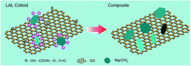
A layered magnesium hydroxide (Mg(OH)2) nanosheet/graphene oxide (GO) composite was synthesized through laser ablation of the Mg target in an aqueous solution with GO. Its mesoporous structure and application as an adsorbent for the removal of methylene blue (MB) and heavy metal ions from water were investigated. Mg(OH)2 nanosheets were organized in situ from the strong reaction between the laser-ablated Mg species and water molecules. The GO nanosheet served as a heterogeneous nucleation and growth site for sheet-like Mg(OH)2 nanocrystals. The resulting porous Mg(OH)2/GO nanosheet composite had a high specific surface area of 310.8 m2 g−1 and a pore volume of 1.031 cm3 g−1. These characteristics show that the composite could be an excellent adsorbent. The composite exhibited a maximum adsorption capacity of 532 mg g−1 at 298 K for typical contaminants of MB, and over 300 mg g−1 for heavy metal ions Zn2+ and Pb2+.


Introduction

The contaminants that contribute to pollution, including dyes and heavy metal ions, released from industrial waste produced by the textiles, paper, leather, plastic, metallurgy, and printing industries, are highly toxic to human beings and the environment.1–4 The removal of these contaminants from wastewater through the use of advanced materials and technologies has elicited considerable attention.5–10 Dyes can be typically removed in two ways. One is to break down the molecular structure of organic dyes, thereby leading to their degradation, including biodegradation5 and photocatalytic degradation.6 The other is to enrich dyes through different media, such as membrane separation,7,8 coagulation,9 and adsorption,10 which are then separated afterward through different procedures. For heavy metal ion removal, adsorption method has been applied the most.11,12 Adsorption technique is an easy, effective, and economic process for removing dyes and heavy metal ions from aqueous solutions.10–13 Thus, seeking for low-cost and efficient adsorbents of nanoscale materials with a high specific surface area is highly important. Graphene possesses a unique layer structure of sp2-hybridized carbon atoms and a high theoretical specific surface area of 2630 m2 g−1.14,15 Graphene oxide (GO), as an oxidation state of graphene, has a wide range of negatively charged oxygen-containing groups, such as hydroxyl (OH), epoxide (C–O–C), carbonyl (C[double bond, length as m-dash]O), and carboxyl (COOH).16 Thus, GO has strong π–π interactions with the aromatic moieties existing in many dyes, which make it a good candidate material as an adsorbent for dyes,17 and the negatively charged surface attracts heavy metal ions.12 However, the use of GO as adsorbents for contaminant depuration remains limited. Separating GO from aqueous solutions is difficult because of GO's good solubility in water.18 However, the network structure of GO provides nucleation and growth sites for other inorganic materials.16,19 This feature ensures the possible assembly of inorganic materials and the resulting interaction with inorganic materials in the network structure.20–24 Magnesium hydroxide (Mg(OH)2), with a basic layered unit of brucite, has a hexagonal symmetry (C6-type) structure, and nanoscale Mg(OH)2 crystalline often exhibits a nanosheet morphology similar to that of GO.25,26 The co-existing hydroxyl radicals and similar layered structure in both GO and Mg(OH)2 may be favorable for the composition of two structures with enhanced interaction and synergistic effects.25,27 Mg(OH)2 can effectively serve as a spacer to support contiguous graphene; GO could also prevent Mg(OH)2 from stacking together.27 As a typical candidate material for fire retardation28 and pollutant removal,25 environment-friendly and low-cost Mg(OH)2 nanocrystals have recently attracted an increasing amount of attention.25,26 Graphene-based Mg(OH)2 nanocomposites with a high specific area and mesoporous structure possess excellent adsorption ability for contaminant molecules and ions.25,27 Developing an in situ assembly process to ensure the uniform growth and assembly of Mg(OH)2 nanocrystalline onto GO nanosheets is thus beneficial. Laser ablation in liquid (LAL) is widely utilized to obtain highly reactive colloidal clusters through the strong reaction between the laser-ablated target species and the surrounding solution molecules during the expansion of plasma plume.29–31 LAL-induced positively or negatively charged clusters can be further employed as reactive precursors for the organization of various functional materials and composite structures.32–35

In this paper, we present the unique organization between layered Mg(OH)2 and GO nanosheets during the LAL process of the Mg target in aqueous suspension with GO. By taking advantage of the excellent applications of Mg(OH)2 in waste removal, we investigate the ability of such a composite to function as an adsorbent for the efficient removal of dyes and heavy metal ions. The maximum adsorption capacity of as-prepared Mg(OH)2/GO composites for methylene blue (MB) has been demonstrated to be as high as 532 mg g−1. The dye capture process follows a pseudo second-order kinetic model, and the adsorption rate is controlled by external and intra-particle diffusion. For the adsorption equilibrium process, the adsorption isotherm fits both Langmuir and Freundlich models well. In the case of heavy metal ions, the equilibrium adsorption capacities of Zn2+, Pb2+, Cu2+, and Ni2+ are 327.7, 344.4, 215.5, and 174.7 mg g−1, respectively, and the corresponding removal efficiencies are 99.9%, 99.6%, 62.1%, and 57.2%, respectively. Adsorption capacity and removal efficiency reach a high level for the removal of heavy metal ions.

Experimental section

Materials and methods

GO was fabricated according to a modified Hummers method.36,37 Before ablation, the Mg plate (99.9% purity) was polished with abrasive paper with different roughness values and ultrasonically rinsed with ethanol and deionized water (18.2 Ω). The magnesium target was submerged in a vessel filled with 15 mL aqueous solution of GO (Fig. S1a). The vessel was then installed onto a controlled turntable, which was set to rotate continuously (10 rpm). The plate was ablated for 20 min by a fundamental Nd:YAG laser (1064 nm) with a 10 Hz pulse repetition rate, 6 ns pulse duration, and 100 mJ per pulse energy. Brown flocculent precipitates appeared as soon as ablation was completed (Fig. S1b), and the product was collected through centrifugation and dried for subsequent characterization. For comparison, the Mg plate was also ablated in another vessel filled with pure water. The resulting colloid is shown in Fig. S1c.

Structure and morphological characterization

The morphology of the as-synthesized composite was investigated through field-emission scanning electron microscopy (SEM) (Sirion 200). The structure was investigated through transmission electron microscopy (TEM) (JEOL, JEM-2010) with 200 kV acceleration voltage. The phase structure of the powder products were analyzed through X-ray diffraction (XRD) with a Philips X'Pert system with Cu Kα radiation (λ = 0.15419 nm, scan step size = 0.033°, and time per step = 180 s). Nitrogen adsorption–desorption isotherms were measured with an Omnisorp 100CX (Beckman Coulter) analyzer.

Adsorption measurement of organic contaminants

Adsorption experiments were conducted with Mg(OH)2/GO composite as the adsorbent for an MB solution in glass bottles at room temperature. During the adsorption experiments, the Mg(OH)2/GO composite was separated from the mixture via centrifugation. At time t = 0 and t = t, the MB concentrations were measured with a UV-vis spectrophotometer (UV2550, Shimazu) at 663 nm. The adsorption capacity at time t, qt (mg g−1), was calculated by
 
image file: c6ra02914k-t1.tif(1)
where C0 and Ct (mg L−1) are the concentrations of MB at the initial period and time t, respectively. V is the volume of the solution (L), and w is the mass of the adsorbent used (in grams).

Adsorption measurement of heavy metal ions

Four types of heavy metal ions, namely, Zn2+, Pb2+, Cu2+, and Ni2+, were selected. Adsorption experiments were conducted with Mg(OH)2/GO (10 mg) as an adsorbent for a solution (approximately 165 mg L−1, 20 mL) in glass bottles at room temperature. The specific initial concentrations of Zn2+, Pb2+, Cu2+ and Ni2+ were detected to be 163.92, 172.84, 173.44 and 152.72 mg L−1 by inductively coupled plasma-atomic emission spectrometer (ICP-AES), respectively. The pH of each solution was adjusted by using 0.1 M HCl or 0.1 M NaOH: Zn2+ in pH 5.0 ± 0.1, Pb2+ in pH 5.0 ± 0.1, Cu2+ in pH 6.0 ± 0.1, and Ni2+ in pH 5.0 ± 0.1. The residual concentration of the heavy metal ions was also determined with the same ICP-AES (AtomScan Advantage Instrument, Thermo Jarrell-Ash Corporation, USA).

Results and discussion

Formation of the Mg(OH)2/GO nanocomposite

Usually, Mg(OH)2 produced through laser ablation in H2O has a positively charged outer surface,26,38 and the GO sheet prepared through the Hummers method has a negatively charged surface.16 As shown in Scheme 1, when Mg(OH)2 formed in the solution, the positively charged Mg(OH)2 flakes were rapidly attracted by the negative charge of GO and then combined through electrostatic attraction. Such self-assembling composites can be further stabilized by other noncovalent interactions (van der Waals interactions and hydrogen bonding) as well as chemisorption between the Mg(OH)2 flakes and groups containing oxygen (carboxylic, hydroxyl, and epoxy groups) existing on the GO surfaces. After laser ablation, brown precipitates were generated gradually, and the suspension became transparent gradually. This result indicates that the colloid electrostatic self-assembly process was driven by the electrostatic force between the positive Mg(OH)2 and negative GO sheets.
image file: c6ra02914k-s1.tif
Scheme 1 Illustration of the formation of the Mg(OH)2/GO composite.

Morphology and phase structure

Fig. 1a shows a typical SEM image of the as-prepared Mg(OH)2/GO composite. Mg(OH)2 flakes with a hexagonal structure (same morphology in Fig. S2a) are perpendicular to the GO sheets and create a flower-like morphology with a size of a few micron meters. The well-defined flower-like structure consists of numerous flakes and pores, which could indicate that the composite has a high specific surface area. The Mg(OH)2 flakes are all perpendicular to the GO plane and thus construct numerous open pores (Fig. 1a) in larger size. Fig. 1b shows the overall TEM image of the as-synthesized Mg(OH)2/GO composite. The ultrathin Mg(OH)2 nanoflakes are anchored and enfolded on rugate GO nanosheets. No separated Mg(OH)2 flakes exist. The inset in Fig. 1b shows the formation of mesoporous pores with a size of less than 4 nm in diameter. The high-resolution TEM (HRTEM) image for an individual Mg(OH)2 flake shows clear lattice fringes (Fig. 1c). The lattice distance is 0.228 nm, which corresponds to the (101) planes of Mg(OH)2. Corresponding selected area electron diffraction (Fig. 1d) along the [101] zone axis yielded a hexagonal spot pattern matching those expected for Mg(OH)2 sixfold symmetry.
image file: c6ra02914k-f1.tif
Fig. 1 (a) Typical SEM image and (b) overall TEM of Mg(OH)2/GO nanoflower. The inset in (b) is a magnified image of the porous structure. (c) HRTEM image of Mg(OH)2 flakes. (d) Corresponding SEAD pattern of the nanoflake in (c). (e) XRD pattern of the Mg(OH)2/GO composite.

Fig. 1e presents the XRD spectra of the product. All diffraction peaks can be well assigned to brucite Mg(OH)2 (JCPDF no. 00-44-1482) with a hexagonal cell (a = 3.1442 Å and c = 4.7770 Å). No peaks from other phases were observed, indicating the high purity of the synthesized materials. Compared with pure Mg(OH)2 produced through LAL method (Fig. S2b), the strongest diffraction of the Mg(OH)2/GO composite is (101) instead of (001), indicating that the growth of the crystals would be preferably stacked along the (101) planes of brucite when GO exists. Both XRD patterns show a non-uniform broadening of peak, which may be caused by various disorders, such as stack faults or interstratifications in layered materials.26 These results demonstrate that GO sheets were involved in the growth process of Mg(OH)2 and limited the nucleation and growth of Mg(OH)2 crystalline.

N2 adsorption and desorption

Prior to investigating the behavior of organic dye removal in water, the N2 adsorption–desorption isotherm for the synthesized mesoporous Mg(OH)2/GO composite was investigated, as shown in Fig. 2. According to the classification of adsorption isotherms by International Union of Pure and Applied Chemistry, the one in this study is a type-IV isotherm with a significant hysteresis loop.39 This finding further indicates that the Mg(OH)2/GO composite has a typical mesoporous structure. From the adsorption branch of the isotherm, the specific surface area was calculated to be 310.8 m2 g−1 through multi-point Brunauer–Emmett–Teller method, and the most probable pore width is 15.5 nm calculated using the Barrett–Joyner–Halenda model. Another probable pore was observed at 3.6 nm, which is consistent with the TEM result (inset of Fig. 1b). The distribution of pore width is in the range of a typical mesoporous structure, conforming with the result of isotherm type. The total pore volume of the Mg(OH)2/GO composite is 1.031 cm3 g−1 (inset of Fig. 2). The specific surface area of the composite is substantially larger than that of pure Mg(OH)2 (218.8 m2 g−1). The high pore volumes and large specific surface area of the composite should guarantee adsorption performance in pollution in water.
image file: c6ra02914k-f2.tif
Fig. 2 Nitrogen adsorption–desorption isotherm for nitrogen measured at 77 K and corresponding pore width distribution (inset).

Organic contaminant adsorption

To evaluate the efficiency of Mg(OH)2, GO, and Mg(OH)2/GO composites in MB, the adsorption process of these materials was determined by monitoring the concentration decrease in initial MB. Experiments were conducted on several bottles with 20 mg adsorbents and 20 mL MB solution (100 mg L−1). The MB solution after adsorption was separated through centrifugation at designed time intervals for 2 h. The result is shown in Fig. 3. The adsorption capacity of Mg(OH)2 is the lowest, demonstrating that Mg(OH)2 is not a suitable adsorbent for MB. A similar conclusion can be obtained from the MB molecular structure (Fig. S3) and the positively charged nature of Mg(OH)2. The UV-vis spectra of MB adsorbed on GO are shown in Fig. 3b. The main UV-vis adsorption peaks exhibit a red shift in extremely short time because of the complexation between MB molecules and GO, which caused the MB molecules to become monomers and protonated MB species with different adsorption peaks in UV-vis spectra.40,41 As shown, the peaks at 676 nm assigned to adsorbed MB monomers. While, the new generated peak at 753 nm assigned to protonated MB. With no appearance of 663 nm peak, GO showed an excellent adsorption property for MB. However, separating GO from the solution is difficult because of its excellent solubility in water. Combining Mg(OH)2 and GO into Mg(OH)2/GO composite can resolve this defect, as shown in Fig. 3c. The intense MB main peak at 663 nm decreased gradually.
image file: c6ra02914k-f3.tif
Fig. 3 UV-vis spectra of MB solution treated with (a) Mg(OH)2, (b) GO, and (c) Mg(OH)2/GO composite (C0 = 100 mg L−1, t = 2 h, V = 20 mL, adsorbent dose = 20 mg).

To investigate the adsorption mechanism, the adsorption time of MB on Mg(OH)2/GO was extended to 36 h. Fig. 4a and b show the concentration decrease and adsorption quantity of MB on the Mg(OH)2/GO composite as a function of contact time. Corresponding digital pictures of the MB solution after adsorption are shown in Fig. S4. The concentration decreased sharply within the first 10 min and subsequently decreased gradually close to 30% after 60 min. Afterward, the concentration still changed slowly until the contact time was extended to 36 h. The inset of Fig. 4a shows that the color of the MB solution became lighter as contact time extended. The maximum adsorption capacity was calculated to be 88.2 mg g−1 with eqn (1). MB is known as a cationic dye (Fig. S3). Mg(OH)2 flakes were anchored and enfolded on GO nanosheets, and the surface of the Mg(OH)2/GO composite was covered by GO with numerous negative charges on the surface. The electrostatic interaction between MB molecules and adsorbents is mainly responsible for the superior adsorption of the Mg(OH)2/GO composite.


image file: c6ra02914k-f4.tif
Fig. 4 (a) Ct/C0 versus time plot for adsorption of the MB solution. (b) Variation in adsorption capacity with contact time for MB on the Mg(OH)2/GO composite. (c) Pseudo second-order fitting of the kinetic adsorption process. (d) Intra-particle diffusion kinetics of MB adsorption on mesoporous Mg(OH)2/GO composite at room temperature (C0 = 100 mg L−1, t = 36 h, V = 20 mL, Mg(OH)2/GO composite dose = 20 mg).

To further explore the kinetics of MB adsorption on the Mg(OH)2/GO composite, a pseudo second-order kinetic model and intra-particle diffusion kinetics were employed to analyze the experimental data.

The pseudo second-order model based on adsorption capacity has the formula42,43

 
image file: c6ra02914k-t2.tif(2)
where qt and qe are adsorption capacity at time t and at equilibrium (mg g−1), respectively, and k2 is the pseudo second-order rate constant (g mg−1 min−1).

By integrating eqn (2) and applying the boundary conditions t = 0 to t = t and qt = 0 to qt = qt, we obtain

 
image file: c6ra02914k-t3.tif(3)

Obviously, k2 and qe can be obtained from the intercept and slope in the plot t/qtt.

The initial adsorption rate, V0, can be calculated with

 
V0 = k2qe2. (4)

The plot of t/qt versus t is shown in Fig. 4c. According to the formula above, the obtained parameters qe, k2, and initial adsorption rate V0 are 87.7 mg g−1, 3.88 × 10⁻⁴ g mg−1 min−1, and 2.99 mg g−1 min−1, respectively (as shown in Table S1). The large value of the correlation coefficients (R2 > 0.99) implies that MB capture by the Mg(OH)2/GO composite follows the pseudo second-order kinetic model.

MB adsorption was carried out under a strong mixing condition at a high concentration. According to previous results reported by SurendraKumar44 and Kunwar P. Singh,45 the rate of adsorption should be governed by intra-particle diffusion transport. The equation for this was utilized to evaluate the intra-particle diffusion kinetic model, which means the dye adsorbed varied more relatively with t1/2 rather than with contact time t. The model is expressed as

 
image file: c6ra02914k-t4.tif(5)
where kdi is the rate parameter of stage i (mg g−1 min−1/2) and Ci represents the thickness of the boundary layer, which can be obtained by the slope and intercept of the straight line of qt against t1/2 at each stage. The larger Ci is, the larger the boundary layer effect is. For each stage of diffusion, qt versus t1/2 should be linear. If the line of intra-particle diffusion passes through the origin, then the rate-limiting process is decided only by intra-particle diffusion; otherwise, it is also governed by film diffusion.

As shown in Fig. 4d, the plots are not linear over the entire time range, implying that more than one process affects MB adsorption. The plots indicate that three steps occur and can be explained by the adsorbate rapidly adsorbed on the external surface of the adsorbent (film diffusion) and intra-particle diffusion. During the first 10 min, rapid external adsorption occurred, which resulted from the electrostatic attraction between negatively charged GO and positively charged MB molecules and high initial MB concentration. This is the film diffusion process. In the next stage, the adsorption rate decreased as the transportation process occurred within the particles. Intra-particle diffusion is not the only rate-limiting process because the line of stage 2 does not go through the origin point. The last stage is final equilibrium stage with a low MB concentration, which resulted in the further slowdown of intra-particle diffusion. To sum up, the adsorption rate is controlled by both external and intra-particle diffusion. From the slopes of each stage (as shown in Fig. 4d and Table S2), the relationship kd1 > kd2 > kd3 was obtained. This relationship represents the rate decrease. Moreover, MB concentration gradually decreased with time. Thus, adsorption rate is significantly affected by adsorbate concentration during the adsorption process.

To investigate the adsorption capacity of the Mg(OH)2/GO composite at different aqueous equilibrium concentrations, the adsorption isotherm was considered. Fig. 5a shows the adsorption of MB on the Mg(OH)2/GO composite as a function of initial concentration (from 25–1750 mg L−1). The equilibrium adsorption capacity of the Mg(OH)2/GO composite continuously increased with increasing initial MB concentration. The adsorption capacity was kept almost constant when the initial concentration increased to 1750 mg L−1. The equilibrium adsorption capacity for MB reached 532 mg g−1. The inset of Fig. 5a illustrates the effect of initial MB concentration on removal efficiency. Removal efficiency reached almost 100% at a low initial concentration and then gradually decreased with adjustment of the initial concentration increase. This fact shows that MB gradually anchored on the surface of GO and filled the pores of the Mg(OH)2/GO composite as the concentration increased; hence, removal efficiency declined at higher concentrations.


image file: c6ra02914k-f5.tif
Fig. 5 (a) Plot of equilibrium adsorption capacity versus initial concentration. Inset: effect of initial MB concentration on removal efficiency. (b) Linearized Langmuir isotherm and (c) linearized Freundlich isotherm for MB adsorption by the Mg(OH)2/GO composite. (d) Isotherm of MB on the Mg(OH)2/GO composite. The nonlinear data fit the Langmuir and Freundlich isotherm models (C0 = 25–1750 mg L−1, t = 36 h, V = 20 mL, Mg(OH)2/GO dose = 20 mg).

In addition, to investigate the mechanism of isothermal adsorption, the experiment data were analyzed with both Langmuir and Freundlich isotherms. The Langmuir isotherm model supposes that the adsorption is localized in a monolayer, and no interaction exists between the adsorbate molecules. This condition means dye molecules can occupy a finite number of identical sites, and no other molecules can attach to them. The adsorption energy for each molecule is uniform, and no transmigration of adsorbate occurs on the surface of the adsorbent.46 The Langmuir equation is expressed as

 
image file: c6ra02914k-t5.tif(6)

The linearized form of the Langmuir isotherm is

 
image file: c6ra02914k-t6.tif(7)
where qm is the maximum adsorption capacity (mg g−1), Ce is the equilibrium concentration of the MB solution (mg L−1), and kL is the equilibrium constant (L mg−1). All these parameters can be calculated by the slope and intercept of the fitted line: Ce/qeCe.

By contrast, the Freundlich isotherm model is an empirical equation and assumes that the adsorption is multi-layer.47 The Freundlich model is expressed as

 
qe = kFCe1/n. (8)

The linearized form of the Freundlich isotherm is

 
image file: c6ra02914k-t7.tif(9)
where qe is the equilibrium adsorption capacity (mg g−1) and Ce is the equilibrium concentration (mg L−1); both were obtained from the experiment. kF and 1/n are the Freundlich characteristic constants, which indicate the adsorption capacity and adsorption intensity. These two can be calculated by the slope and intercept of the fitted line log[thin space (1/6-em)]qe ∼ log[thin space (1/6-em)]Ce. The value of 1/n stands for the degree of difficulty of adsorption, and it denotes easy adsorption only when 0.1 < 1/n < 0.5.

The Langmuir and Freundlich isotherm models were both applied to fit the adsorption equilibrium data of MB onto the Mg(OH)2/GO composite. The detailed results are shown in Fig. 5b to c and Table S3. The adsorption data fitted both Langmuir and Freundlich models well because the values of R2 in the two models approximate 0.99. This result discloses that the adsorption process was either monolayer or multi-layer and occurred on the homogeneous surface. The value of Freundlich constant 1/n is 0.36, which is between 0 and 0.5; this value means adsorption occurred easily.

The nonlinear fit of the two models, as shown in Fig. 5d, indicates that the Langmuir model isotherm closely coincided with the experimental data at a high concentration. The Freundlich model fitted the data at a low concentration. The R2 value of the Langmuir model (0.967) almost reached 0.99. According to eqn (7), the maximum adsorption capacity for MB was calculated to be 555.6 mg g−1, which is close to the experimental value of 532 mg g−1.

Heavy metal ions adsorption

Owing to industrial development, heavy metal pollution has become a serious global environmental issue. Given that the synthesized mesoporous Mg(OH)2/GO nanocomposites exhibited a desirable adsorption performance in MB, heavy metal ion removal experiments were also conducted to evaluate the pollutant treatment capacity of Mg(OH)2/GO. As known, Zn, Pb, Cu and Ni are ubiquitous in the environment but hazardous at the high concentration in the form of ion state, leading to the poisonousness of human being and other animals or plants. Herein, such four types of heavy metal ions (Zn2+, Pb2+, Cu2+, and Ni2+) were considered for the adsorption property assessment of Mg(OH)2/GO in water. We observed that the Mg(OH)2/GO nanoflower was efficient in the removal of selected metal ions in water. Fig. 6 shows the capacity and removal efficiency of each metallic species; the corresponding data are shown in Table S4. The removal efficiency of Zn2+ and Pb2+ almost reached 100%, and their equilibrium adsorption capacities were as high as 327.7 and 344.4 mg g−1, respectively. The removal percentage of Cu2+ and Ni2+ was around 60%, and their equilibrium adsorption capacities were 216 and 175 mg g−1, which are also at a high level for heavy metal ion adsorption.3,4 Overall, the adsorption capacities of as-synthesised Mg(OH)2/GO for different heavy metal ion is Pb2+ > Zn2+ > Cu2+ > Ni2+ and the removal efficiency is Zn2+ > Pb2+ > Cu2+ > Ni2+. In a single metal species system, the adsorption capacity and removal efficiency would be affected by many factors, such as pH, solution concentrations, interaction between adsorbents and heavy metal ions. The difference of adsorption capacity and removal efficiency among four heavy metal ions is due to different adsorption mechanisms they involved.48 Therefore, Mg(OH)2/GO nanocomposites are potential absorbents for removing not only dye but also heavy metal ions in contaminated water.
image file: c6ra02914k-f6.tif
Fig. 6 Capacity and removal efficiency of heavy metal ion adsorption by Mg(OH)2/GO from synthetic wastewater (C0(Zn2+) = 163.92 mg L−1, C0(Pb2+) = 172.84 mg L−1, C0(Cu2+) = 173.44 mg L−1, C0(Ni2+) = 152.72 mg L−1, which were determined by ICP-AES; t = 24 h; V = 20 mL; adsorbent dose = 10 mg).

Conclusions

In situ LAL method was utilized to obtain Mg(OH)2 flakes composited on GO nanosheets as triggered by the colloidal electrostatic self-assembly between the positively charged Mg(OH)2 flakes and negatively charged GO sheets. The Mg(OH)2 flakes dispersed uniformly onto the surface of the GO sheets and allowed GO to be easily separated from the aqueous solution. GO prevented the preferably grown Mg(OH)2 flakes from stacking together and resulted in a high specific surface area and porous structure. The as-synthesized composite presented excellent adsorption performance for MB and selected heavy metal ions. The adsorption of MB onto Mg(OH)2/GO had a large adsorption capacity of 532 mg g−1 and a rapid adsorption process. The adsorption process followed pseudo second-order and intra-particle diffusion kinetics. The isotherm data fitted both Langmuir and Freundlich isotherms well. With regard to the composite adsorption test for heavy metal ions, both adsorption capacity and removal efficiency were at a high level.

Acknowledgements

This work was supported by the National Basic Research Program of China (2014CB931704), the National Natural Science Foundation of China (NSFC, No. 11304315, 11504375, 51571186, 51401206) and CAS Key Technology Talent Program.

Notes and references

  1. A. Houas, H. Lachheb, M. Ksibi, E. Elaloui, C. Guillard and J. M. Herrmann, Appl. Catal., B, 2001, 31, 145 CrossRef CAS.
  2. C. Ràfols and D. Barceló, J. Chromatogr. A, 1997, 777, 177 CrossRef.
  3. H. Chen, X. X. Wang, J. X. Li and X. K. Wang, J. Mater. Chem. A, 2015, 3, 6073 CAS.
  4. Z. H. Dong, D. Wang, X. Liu, X. F. Pei, L. W. Chen and J. Jin, J. Mater. Chem. A, 2014, 2, 5034 CAS.
  5. U. Shedbalkar, R. Dhanve and J. Jadhav, J. Hazard. Mater., 2008, 157, 472 CrossRef CAS PubMed.
  6. I. K. Konstantinou and T. A. Albanis, Appl. Catal., B, 2004, 49, 1 CrossRef CAS.
  7. S. Sachdeva and A. Kumar, J. Membr. Sci., 2009, 329, 2 CrossRef CAS.
  8. R. V. Kumar, A. K. Ghoshal and G. Pugazhenthi, Ecotoxicol. Environ. Saf., 2015, 121, 73 CrossRef CAS PubMed.
  9. B. Y. Shi, G. H. Li, D. S. Wang, C. H. Feng and H. X. Tang, J. Hazard. Mater., 2007, 143, 567 CrossRef CAS PubMed.
  10. M. Rafatullah, O. Sulaiman, R. Hashim and A. Ahmad, J. Hazard. Mater., 2010, 177, 70 CrossRef CAS PubMed.
  11. X. X. Ye, S. H. Kang, H. M. Wang, H. Y. Li, Y. X. Zhang, G. Z. Wang and H. J. Zhao, J. Hazard. Mater., 2015, 289, 210 CrossRef CAS PubMed.
  12. Z. Q. Niu, L. L. Liu, L. Zhang and X. D. Chen, Small, 2014, 10, 3434 CrossRef CAS PubMed.
  13. A. Dąbrowski, Adv. Colloid Interface Sci., 2001, 93, 135 CrossRef.
  14. J. G. Yu, L. Y. Yu, H. Yang, Q. Liu, X. H. Chen, X. Y. Jiang, X. Q. Chen and F. P. Jiao, Sci. Total Environ., 2015, 502, 70 CrossRef CAS PubMed.
  15. K. C. Kemp, H. Seema, M. Saleh, N. H. Le, K. Mahesh, V. Chandra and K. S. Kim, Nanoscale, 2013, 5, 3149 RSC.
  16. D. R. Dreyer, S. J. Park, C. W. Bielawski and R. S. Ruoff, Chem. Soc. Rev., 2010, 39, 228 RSC.
  17. L. J. Chen, J. J. Yang, X. P. Zeng, L. Z. Zhang and W. X. Yuan, Mater. Express, 2013, 3, 281 CrossRef CAS.
  18. W. Gao, L. B. Alemany, L. J. Ci and P. M. Ajayan, Nat. Chem., 2009, 1, 403 CrossRef CAS PubMed.
  19. X. Huang, X. Y. Qi, F. Boey and H. Zhang, Chem. Soc. Rev., 2012, 41, 666 RSC.
  20. C. R. Li, Y. Huang and Z. Lin, J. Mater. Chem. A, 2014, 2, 14979 CAS.
  21. B. J. Li, H. Q. Cao, J. F. Yin, Y. A. Wu and J. H. Warner, J. Mater. Chem., 2012, 22, 1876 RSC.
  22. X. J. Liu, L. K. Pan, T. Lv, T. Lu, G. Zhu, Z. Sun and C. Q. Sun, Catal. Sci. Technol., 2011, 1, 1189 CAS.
  23. Z. Y. Yin, S. X. Wu, X. Z. Zhou, X. Huang, Q. C. Zhang, F. Boey and H. Zhang, Small, 2010, 6, 307 CrossRef CAS PubMed.
  24. J. G. Radich, R. Dwyer and P. V. Kamat, J. Phys. Chem. Lett., 2011, 2, 2453 CrossRef CAS.
  25. M. D. Liu, J. Xu, B. Cheng, W. K. Ho and J. G. Yu, Appl. Surf. Sci., 2015, 332, 121 CrossRef CAS.
  26. C. H. Liang, T. Sasaki, Y. Shimizu and N. Koshizaki, Chem. Phys. Lett., 2004, 389, 58 CrossRef CAS.
  27. B. J. Li, H. Q. Cao and G. Yin, J. Mater. Chem., 2011, 21, 13765 RSC.
  28. H. Gui, X. H. Zhang, W. F. Dong, Q. G. Wang, J. M. Gao, Z. H. Song, J. M. Lai, Y. Q. Liu, F. Huang and J. L. Qiao, Polymer, 2007, 48, 2537 CrossRef CAS.
  29. H. M. Zhang, C. H. Liang, J. Liu, Z. F. Tian and G. S. Shao, Carbon, 2013, 55, 108 CrossRef CAS.
  30. J. Liu, C. H. Liang, Z. F. Tian, S. Y. Zhang and G. S. Shao, Sci. Rep., 2013, 3, 1741 Search PubMed.
  31. Z. F. Tian, C. H. Liang, J. Liu, H. M. Zhang and L. D. Zhang, J. Mater. Chem., 2011, 21, 18242 RSC.
  32. C. H. Liang, Y. Shimizu, M. Masuda, T. Sasaki and N. Koshizaki, Chem. Mater., 2004, 16, 963 CrossRef CAS.
  33. H. B. Zeng, X. W. Du, S. C. Singh, S. A. Kulinich, S. K. Yang, J. P. He and W. P. Cai, Adv. Funct. Mater., 2012, 22, 1333 CrossRef CAS.
  34. Y. X. Ye, P. P. Wang, E. M. Dai, J. Liu, Z. F. Tian, C. H. Liang and G. S. Shao, Phys. Chem. Chem. Phys., 2014, 16, 8801 RSC.
  35. Y. X. Ye, P. P. Wang, H. M. Sun, Z. F. Tian, J. Liu and C. H. Liang, RSC Adv., 2015, 5, 45038 RSC.
  36. W. S. Hummers Jr and R. E. Offeman, J. Am. Chem. Soc., 1958, 80, 1339 CrossRef.
  37. Y. X. Xu, H. Bai, G. W. Lu, C. Li and G. Q. Shi, J. Am. Chem. Soc., 2008, 130, 5856 CrossRef CAS PubMed.
  38. T. X. Phuoc, B. H. Howard, D. V. Martello, Y. Soong and M. K. Chyu, Opt. Laser Eng., 2008, 46, 829 CrossRef.
  39. K. S. W. Sing, D. H. Everett, R. A. W. Haul, L. Moscou, R. A. Pierotti, J. Rouquérol and T. Siemieniewska, Pure Appl. Chem., 1985, 57, 603 CrossRef CAS.
  40. K. Haubner, J. Murawski, P. Olk, L. M. Eng, C. Ziegler, B. Adolphi and E. Jaehne, ChemPhysChem, 2010, 11, 2131 CrossRef CAS PubMed.
  41. K. Y. Jacobs and R. A. Schoonheydt, J. Colloid Interface Sci., 1999, 220, 103 CrossRef CAS PubMed.
  42. Y. S. Ho and G. McKay, Can. J. Chem. Eng., 1998, 76, 822 CrossRef CAS.
  43. I. A. W. Tan, A. L. Ahmad and B. H. Hameed, J. Hazard. Mater., 2009, 164, 473 CrossRef CAS PubMed.
  44. A. Kumar, S. Kumar and S. Kumar, Carbon, 2003, 41, 3015 CrossRef CAS.
  45. D. Mohan, K. P. Singh, S. Sinha and D. Gosh, Carbon, 2004, 42, 2409 CrossRef CAS.
  46. I. Langmuir, J. Am. Chem. Soc., 1918, 40, 1361 CrossRef CAS.
  47. H. M. F. Freundlich, Z. Phys. Chem., 1906, 57, 385 CAS.
  48. C. K. Liu, R. B. Bai and Q. S. Ly, Water Res., 2008, 42, 1511 CrossRef CAS PubMed.

Footnote

Electronic supplementary information (ESI) available: Digital pictures of GO solution, colloid after laser ablated and MB solution during adsorption process; SEM image and XRD pattern of pure Mg(OH)2; molecule structure of MB, tables of fitting parameters data. See DOI: 10.1039/c6ra02914k

This journal is © The Royal Society of Chemistry 2016
Click here to see how this site uses Cookies. View our privacy policy here.