DOI:
10.1039/C6RA02544G
(Paper)
RSC Adv., 2016,
6, 35977-35990
Investigation on the growth, structural, HOMO–LUMO and optical studies of 1-ethyl-2-[2-(4-hydroxy-phenyl)-vinyl]-pyridinium iodide (HSPI) – a new stilbazolium derivative for third-order NLO applications†
Received
28th January 2016
, Accepted 26th March 2016
First published on 30th March 2016
Abstract
The organic third-order non-linear optical crystal 1-ethyl-2-[2-(4-hydroxy-phenyl)-vinyl]-pyridinium iodide (HSPI), a new derivative of the stilbazolium family, was successfully synthesized and the optical quality single crystal was grown by a slow evaporation technique for the first time. The crystal structure of HSPI was confirmed by single crystal X-ray diffraction studies and it was found that it belongs to the monoclinic system with centrosymmetric space group C2/c. The molecular structure of the grown crystal was further confirmed by 1H NMR and FTIR analysis. Theoretical calculations were performed to derive HOMO–LUMO energies and dipole moment by using the Spartan'14 V1.0.1 program. The UV-Vis-NIR spectral studies exhibit a huge transparency (∼70%) in the visible and near-IR (from 468 to 1100 nm) spectral regions that make it a potential material for non-linear device applications in this spectral range. The luminescence spectrum of the grown crystal showed green emission at 528 nm. The thermal stability of HSPI was found to be 226.6 °C. Mechanical behaviour was estimated by Vickers microhardness test. Dielectric studies were carried out as a function of frequency, and the results are discussed. The growth mechanism of HSPI was assessed by chemical etching studies. The title crystal shows excellent resistance to laser radiation with a high threshold up to 6.93 GW cm−2 and it is compared with other NLO materials. The third-order nonlinear optical susceptibility of HSPI was derived using the Z-scan technique, and it was 4.40 × 10⁻⁴ esu. The negative nonlinear refractive index, n2 = −7.29 × 10⁻¹² m2 W−1, is an indication of self-defocusing optical nonlinearity of the sample. It is believed that HSPI is a promising new candidate for developing efficient photonic and optical power limiting devices.
1. Introduction
There has been significant attention on the synthesis of new materials with sufficiently large third-order nonlinear optical responses that can be used for applications such as 3D optical memory, photodynamic therapies, optical switching, optical modulating, optical computing, and so on.1–3 Recent research shows that π-conjugated organic systems have gained much attention because of their attractive second and third-order optical nonlinearities, high damage resistance, and large electro-optic coefficients.4–6 The delocalised pi electronic structure in organics offers some possibilities to synthesize materials with high NLO response.7 Compounds containing the pyridinium units are widely distributed owing to their strong electron accepting capability shows excellent nonlinear optical properties. Due to its presence in many chemical structures, it finds applications in biomedical and industrial fields, terahertz wave generation, and other device applications.8,9
Considering the stilbazolium derivatives, due to their strong intramolecular charge-transfer (ICT) transition, they showed higher NLO efficiency and superior photophysical and photochemical properties.10 The interest of this type of investigations is based on the fact that the existence of strong Coulomb interactions between a stilbazolium cation and counter anion leading to significant macroscopic nonlinearities. Based on the above properties, it was reported that stilbazolium derivatives show potential applications in fluorescent sensors, indicators11,12 etc.
In the present investigation, our effort has been directed to synthesize the new stilbazolium derivative, 1-ethyl-2-[2-(4-hydroxy-phenyl)-vinyl]-pyridinium iodide (HSPI), hydroxyl-based pyridinium crystals with iodide anion by slow evaporation method. Herein we report the details of synthesis, growth, structural, optical, thermal, mechanical, and electrical properties along with the Z-scan studies to examine the suitability of the grown crystal for nonlinear optical applications.
2. Experimental
2.1 Synthesis, solubility and crystal growth
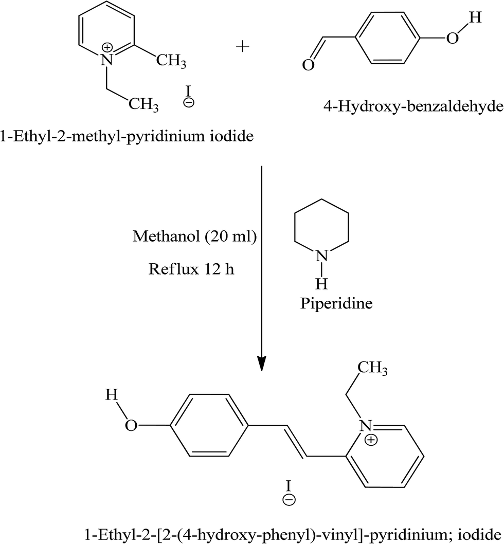
HSPI was synthesized by taking the equimolar ratio of 1-ethyl-2-methyl pyridinium iodide (7.47 g, 30 mmol), 4-hydroxy benzaldehyde (3.66 g, 30 mmol) and methanol (20 ml) with few drops of piperidine (Scheme 1). The above mixture was refluxed for 12 h and then cooled to ambient temperature, yielding HSPI as a yellow solid. The resulting salt was filtered off, washed with diethyl ether, and dried. The successive recrystallization process was adopted to improve the purity of the salt using methanol solvent. The knowledge of solubility in a particular solvent gives information about the growth conditions and is useful for the thermodynamic analysis of solute–solvent interactions. Solubility in methanol and acetonitrile (1![[thin space (1/6-em)]](https://www.rsc.org/images/entities/char_2009.gif) :1) was determined by the gravitational method for the recrystallized salt of HSPI at different temperatures ranging from 30–50 °C. Fig. 1 displays the solubility curve that exhibits a positive temperature coefficient. Based on the solubility data, the saturated growth solution at 30 °C was prepared with continuous stirring for about 2 h. Single crystals of HSPI was obtained by slow evaporation of the solvent (methanol–acetonitrile) at room temperature. Accordingly, a transparent single crystal of dimension 14 × 11 × 8 mm3 was achieved in a growth period of 75 days by the addition of defect-free seed crystal into the saturated solution and is shown in Fig. 2a. The morphology of HSPI was predicted using WinXMorph software,13 where the data obtained from the single crystal XRD study (CIF format) were given as input. The growth morphology of the grown crystals seems to be hexagonal in shape. The indexed morphology is presented in Fig. 2b. It revealed that the major growth rate is directed along a-axis of the crystal compared with other crystallographic axes.
:1) was determined by the gravitational method for the recrystallized salt of HSPI at different temperatures ranging from 30–50 °C. Fig. 1 displays the solubility curve that exhibits a positive temperature coefficient. Based on the solubility data, the saturated growth solution at 30 °C was prepared with continuous stirring for about 2 h. Single crystals of HSPI was obtained by slow evaporation of the solvent (methanol–acetonitrile) at room temperature. Accordingly, a transparent single crystal of dimension 14 × 11 × 8 mm3 was achieved in a growth period of 75 days by the addition of defect-free seed crystal into the saturated solution and is shown in Fig. 2a. The morphology of HSPI was predicted using WinXMorph software,13 where the data obtained from the single crystal XRD study (CIF format) were given as input. The growth morphology of the grown crystals seems to be hexagonal in shape. The indexed morphology is presented in Fig. 2b. It revealed that the major growth rate is directed along a-axis of the crystal compared with other crystallographic axes.
 |
| | Scheme 1 Synthesis scheme for HSPI. | |
 |
| | Fig. 1 Temperature dependent solubility curve for HSPI. | |
 |
| | Fig. 2 (a) As-grown crystal of HSPI (b) typical growth morphology of HSPI. | |
3. Results and discussion
3.1 X-ray diffraction analysis
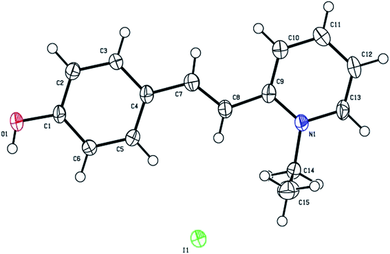
The grown HSPI crystal was subjected to single crystal X-ray diffraction studies to confirm the crystallinity and to estimate the lattice parameters using Rigaku R-AXIS RAPID diffractometer with Mo-Kα (λ = 0.71075 Å). The structure was solved by the direct methods using SHELX97 and refinement was done by using full-matrix least squares on F2 using the SHELX97 program to a final R-value of 0.0478.14 Crystal data and details of the data collection for structure determination are listed in Table 1. From the single crystal XRD data obtained, it is observed that the grown single crystal HSPI crystallizes in monoclinic system with centrosymmetric space group C2/c. The unit cell parameters determined from single crystal X-ray diffraction analysis, and the data are a = 13.464 Å, b = 15.491 Å, c = 14.863 Å, α = γ = 90°, β = 110.524° and cell volume = 2923.23 Å3 with Z = 8. The ORTEP view of HSPI drawn with numbering scheme is shown in Fig. 3 and the crystal-packing diagram is shown in Fig. 4. Selected bond lengths and bond angles are given in Table 2. The possible hydrogen bonds for HSPI are listed in Table 3. Full crystallographic data (cif file) relating to the crystal structure of HSPI has been deposited with the Cambridge Crystallographic Database (CCDC 1419337). The asymmetric unit of the title compound HSPI is composed of a C15H16NO+ cation and I− anion. The cation exists in the trans E-configuration with respect to the ethenyl C7![[double bond, length as m-dash]](https://www.rsc.org/images/entities/char_e001.gif) C8 double bond [1.333(8) Å] with the torsion angle of C4–C7–C8–C9 = 178.7(4)°. To minimize the interaction of hydroxyl proton H1 and H6 at C6 the O1–C1–C6 angle [122.3(5)°] is larger than the O1–C1–C2 angle [117.5(5)°].
C8 double bond [1.333(8) Å] with the torsion angle of C4–C7–C8–C9 = 178.7(4)°. To minimize the interaction of hydroxyl proton H1 and H6 at C6 the O1–C1–C6 angle [122.3(5)°] is larger than the O1–C1–C2 angle [117.5(5)°].
Table 1 Crystal data and structure refinement of HSPI
| Empirical formula |
C15H16INO |
| CCDC |
1419337 |
| Formula weight |
353.20 |
| Temperature |
110 K |
| Wavelength |
0.71075 Å |
| Crystal system, space group |
Monoclinic, C2/c |
| Unit cell dimensions |
a = 13.464(2) Å, α = 90° |
| b = 15.491(2) Å, β = 110.524(3)° |
| c = 14.863(2) Å, γ = 90° |
| Volume |
2903.2(5) Å3 |
| Z |
8 |
| Calculated density |
1.616 g cm−3 |
| Absorption coefficient |
21.955 cm−1 |
| F(000) |
1392.00 |
| Crystal size |
0.200 × 0.200 × 0.150 mm3 |
| Theta range for data collection |
0.0 to 55.0° |
| Completeness to theta = 55.0° |
99% |
| Refinement method |
Full-matrix least-squares on F2 |
| Reflections measured/unique |
13451/3313 [Rint = 0.0663] |
| Variable parameters |
171 |
| Reflection/parameter ratio |
19.37 |
| R indices (all data) |
R1 = 0.0478, wR2 = 0.1128 |
| Goodness of fit indicator |
1.120 |
 |
| | Fig. 3 ORTEP diagram of HSPI. | |
 |
| | Fig. 4 Crystal packing diagram of HSPI. | |
Table 2 Bond lengths (Å) and bond angles (°) in HSPI
| Atoms |
Lengths |
Atoms |
Angles |
| O1–C1 |
1.361(6) |
O1–C1–C2 |
117.5(5) |
| O1–H1 |
0.840 |
C1–O1–H1 |
109 |
| N1–C13 |
1.355(7) |
C1–C2–C3 |
119.6(5) |
| C1–C2 |
1.389(7) |
C2–C3–C4 |
121.8(5) |
| C2–C3 |
1.384(7) |
C3–C4–C7 |
119.4(5) |
| C4–C5 |
1.414(7) |
C7–C8–C9 |
122.4(5) |
| C4–C7 |
1.455(7) |
C4–C7–H4 |
112 |
| C7–H4 |
0.919 |
C4–C5–H5 |
120 |
| C5–C6 |
1.388(7) |
C7–C8–H7 |
115 |
| C8–C9 |
1.455(8) |
C8–C9–C10 |
123.8(5) |
| C9–C10 |
1.399(7) |
C4–C5–C6 |
120.9(5) |
| C10–C11 |
1.361(8) |
C1–C6–C5 |
119.6(5) |
| C11–C12 |
1.393(8) |
C8–C7–H4 |
121 |
| C12–C13 |
1.364(8) |
C9–N1–C14 |
122.3(4) |
| C14–C15 |
1.506(8) |
N1–C9–C8 |
119.2(4) |
| N1–C9 |
1.370(7) |
N1–C13–C12 |
121.6(5) |
| N1–C14 |
1.495(6) |
C13–N1–C14 |
116.1(4) |
| C14–H14A |
0.990 |
N1–C14–H14A |
109 |
| C14–H14AB |
0.990 |
N1–C14–H14B |
109 |
| C15–H15A |
0.980 |
C14–C15–H15A |
109 |
| C15–H15B |
0.980 |
C14–C15–H15B |
109 |
| C15–H15C |
0.980 |
C14–C15–H15C |
109 |
Table 3 Hydrogen bonds for HSPI [Å and deg.]
| D–H⋯A |
D⋯A |
D–H |
H⋯A |
D–H⋯A |
| O1–H1⋯I1 |
3.431(4) |
0.84 |
2.64 |
158.48 |
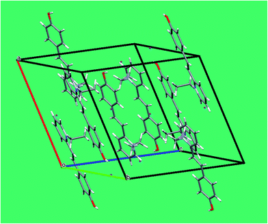
In the crystal packing (Fig. 4), the pyridinium cation is stacked in a parallel manner along the a-axis. The cation–anion (H–I) distance of 2.64 Å (Table 3) is rather shorter than the sum of the van der Waals radii, suggesting that the cation–anion interactions control the packing.15 The H atom attached to O1 linked through O–H⋯I hydrogen bonds between the cation and the anion. In addition, the crystal structure is predominantly stabilized by hydrogen-bonding interactions between the pyridinium donor and the iodine acceptor (C–H⋯O and C–H⋯I interactions). In the conjugated system, the C–C–C, N–C–C, and C–N–C bond angles are close to 120°. It illustrates that the π-electrons in the HSPI crystal are delocalized. Interestingly, the π-conjugated molecular planes are arranged themselves in a head-to-tail fashion along the a-plane with alternating directionality due to the strong ‘push–pull’ electron system.16 Specifically, the benzene ring containing the hydroxyl group from one molecule interacts with the pyridinium moiety from another molecule.
The X-ray powder diffraction studies were carried out to demonstrate the crystallinity by using BRUKER X-ray diffractometer with CuKa radiation (λ = 1.5406 Å). The powdered samples were recorded over the 2θ range of 10–50° at a scanning rate of 0.02° S−1. From the powdered X-ray data, the various planes of reflections were indexed using Powder-X software. The diffraction pattern obtained from experimental powder XRD and single crystal XRD well coincides with each other of varied intensities pattern (Fig. 5). The well-defined sharp peaks at specific 2θ values provide the simplest way of confirming the crystalline phase of grown HSPI crystal.
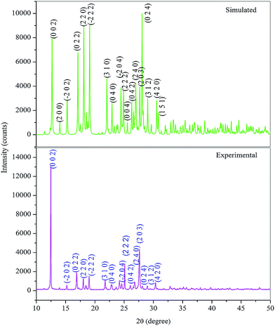 |
| | Fig. 5 Powder X-ray diffractogram of HSPI. | |
3.2 HOMO–LUMO energy gap and MEP analysis
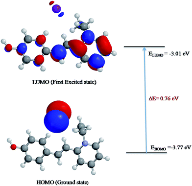
Molecular orbitals can provide valuable insight into bonding and other chemical properties. The HOMO–LUMO energy gap refers to the potential energy difference between the highest occupied molecular orbital (HOMO) and the lowest unoccupied molecular orbital (LUMO). HOMO is the orbital that acts as an electron donor while LUMO is the orbital that mainly serves as an electron acceptor. Molecular orbital with the small frontier orbital gap is associated with the high chemical reactivity, large polarizable, low kinetic stability, and soft nature of the molecule.17,18
To evaluate the energetic behaviour of the title compound, the HOMO–LUMO analysis was carried out by using DFT method at the B3LYP/6-31G (*) basis set level using Spartan'14 V1.0.1 program.19 The input data for this study was taken from the CIF file obtained from single crystal X-ray measurements of HSPI. The plots of MO's (HOMO and LUMO) are shown in Fig. 6. It can be seen from the plots, the HOMO electron density is spread over the iodine anion, while the LUMO electron density is distributed over the whole structure especially on the pyridine ring, C–H (vinyl group) and in the phenyl ring containing a hydroxyl group. The value of energy separation between the HOMO and LUMO was found as 0.76 eV and the value of dipole moment was 14.65 debye, which is greater than that of urea (μ = 1.3732 D). It is concluded that the HSPI crystal possesses small energy difference and greater dipole moment than urea. Moreover, this is due to the π-electron cloud movement from a donor (hydroxy) to acceptor (pyridinium moiety), i.e., intramolecular charge transfer can cause the molecule more polarized and hence ICT must be responsible for the large NLO property of the title crystal. Therefore, the title crystal may have potential applications for the development of NLO devices in future.
 |
| | Fig. 6 Patterns of the HOMO and LUMO molecular orbitals of HSPI obtained at B3LYP/6-31G (*) level. | |
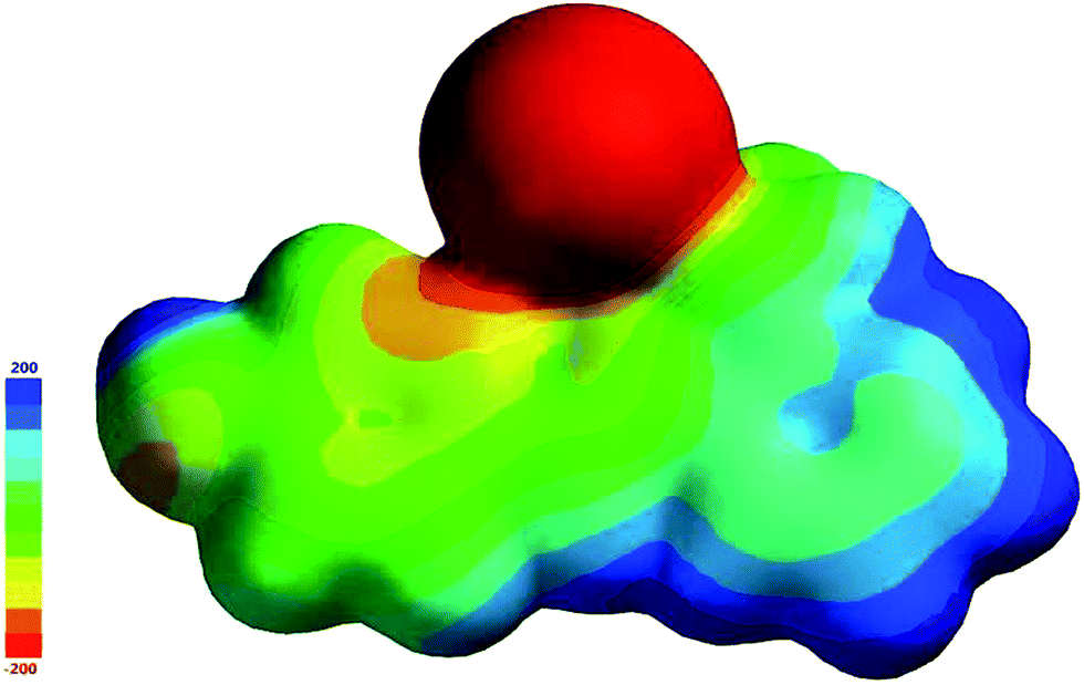
The molecular electrostatic potential is related to the electron density (ED) and is a useful feature to explain the reactive behaviour in both electrophilic and nucleophilic reactions and hydrogen bonding reactions.20 The 3D plots of molecular electrostatic potential (MEP) of HSPI are illustrated in Fig. 7. The color line of the map corresponds to the different potential values ranging from −200 a.u. to 200 a.u., where red, blue and green represents the most negative, most positive and zero electrostatic potential regions respectively. It can be seen that the negative potential sites are localised over the iodine atom, and the positive potential sites are around the pyridinium ring. A region of zero potential covers the remaining carbon atoms in the HSPI crystal. From MEP map, we can conclude that the title crystal can have intramolecular interactions and contains most reactive sites for electrophilic and nucleophilic attack respectively.
 |
| | Fig. 7 Molecular electrostatic potential surface of HSPI. | |
3.3 1H NMR spectral analysis
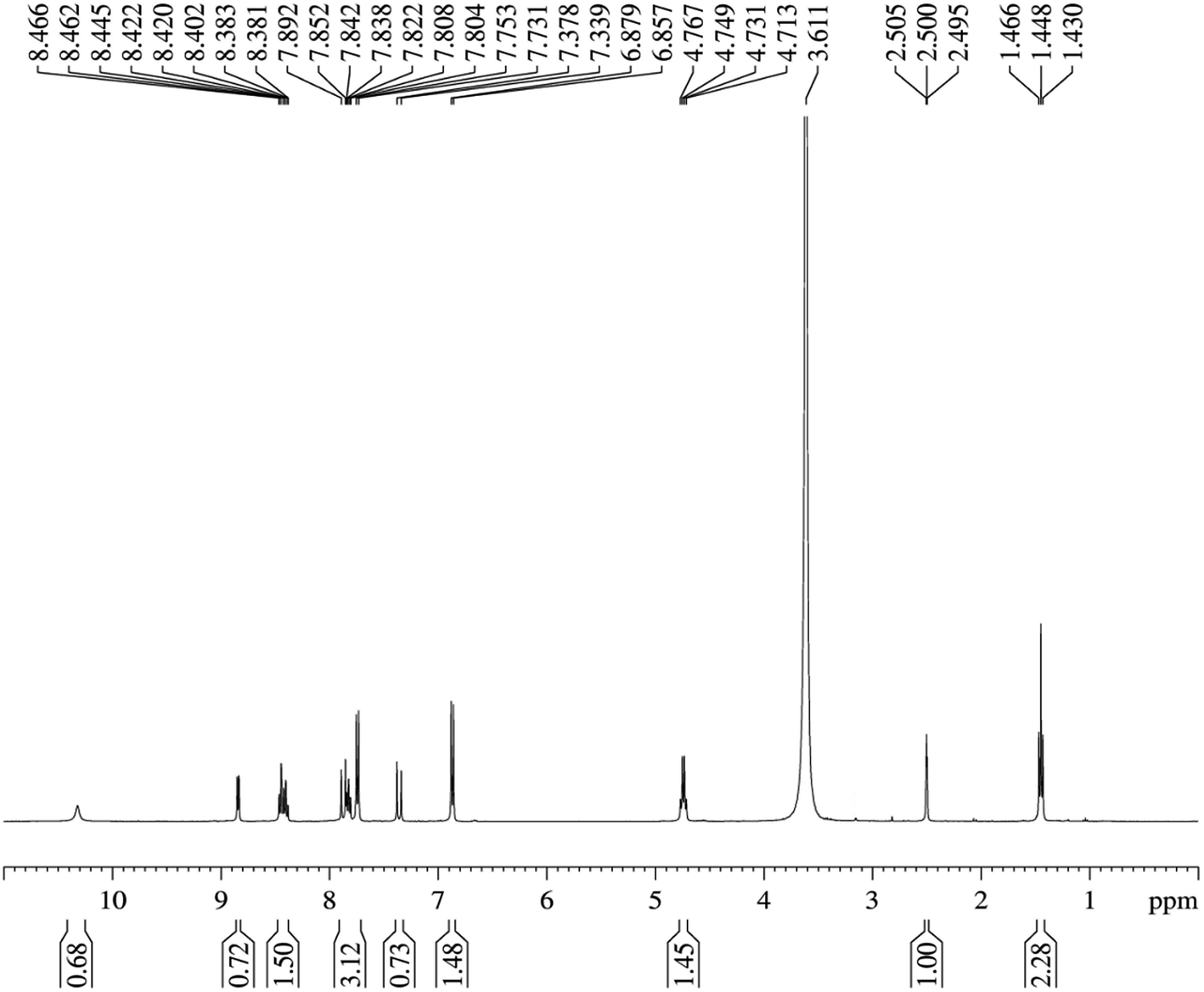
In the 1H NMR spectrum of HSPI (Fig. 8), the quintet at 2.50 ppm and the singlet at 3.611 ppm are assigned to DMSO-d6 and the solvent water. The hydroxyl proton exhibits a singlet signal at 10.319 ppm. In addition, the chemical shift of hydrogens in ethyl group (N–CH2–CH3) attached with pyridine ring gives one triplet signal at 1.448 ppm and quartet at 4.731 ppm. The doublet signals at 6.878 ppm, δ 7.378 ppm, δ 7.807 ppm and δ 7.837 ppm are assigned to ring protons in third, fifth, second and sixth position in the aromatic ring. The two doublets observed at 7.753 ppm, and 7.891 ppm owes to the two olefinic hydrogens (CHCH). The triplets found at 8.401 ppm, and 7.807 ppm is attributed to protons in the fourth and fifth position of the pyridinium ring. Also the hydrogens in the third and sixth position of the pyridinium ring produce doublet peaks at 8.462 ppm and 8.849 ppm, which is the neighbor of (N–CH2–CH3) bond. The molecular structure of HSPI is thus confirmed from the NMR spectrum.
 |
| | Fig. 8 1H NMR spectrum of HSPI. | |
3.4 Fourier transform infrared analysis
The Fourier transform infrared spectrum (FTIR) spectrum was recorded for the HSPI crystal using SHIMADZU instrument by KBr pellet technique in the range of 4000–400 cm−1. The FTIR spectrum recorded for the HSPI crystal are depicted in Fig. 9, and the functional groups were identified in Table 4. The peak assigned at 3172.90 cm−1 belongs to the hydroxyl group (O–H stretching). The peak observed at 1597.06 cm−1 belong to C–C stretching of the olefinic double bond. The band at 1678.07 cm−1 is assigned to aromatic CC stretching vibrations. The sharp peak at 1055.06 cm−1 confirms the formation of the title compound by olefin C–H bond. The peak at 2974 cm−1 is attributed to the alkyl C–H stretching mode. The peaks that are observed at 1560.41 cm−1, 1517.98 cm−1 and 1479.40 cm−1 is due to the aromatic ring in-plane stretching vibrations. The absorption peak observed around 1436.97 cm−1, and 1246.02 cm−1 corresponds to CH2 bending and C–N stretching mode. The para-substituted aromatic ring vibrations mode is seen from the peak at 825.53 cm−1. The 1,2 substituted pyridinium ring gives its C–H bend at 958.62 cm−1. The vibrational frequencies observed between 1100 and 1200 cm−1 are attributed to the in-plane and the frequencies between 750 and 950 cm−1 are assigned to the out of plane ring bending modes of the aromatic ring C–H, respectively.21 From the above observation, the presence of particular functional groups in the title compound was confirmed.
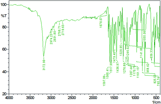 |
| | Fig. 9 FT-IR spectrum for HSPI. | |
Table 4 FTIR wavenumbers and their assignments of HSPI
| Wavenumber (cm−1) |
Assignments |
| 3172.90 |
O–H stretching |
| 1597.06 |
C–C stretch of the olefinic double bond |
| 1678.07 |
Aromatic CC stretching |
| 1055.06 |
Olefinic C–H bond |
| 2974 |
Alkyl C–H stretching |
| 1560.41, 1517.98 and 1479.40 |
Aromatic ring in-plane stretching |
| 1436.97 and 1246.02 |
CH2 bending and C–N stretching |
| 825.53 |
para-Substituted aromatic ring vibrations |
| 958.62 |
C–H bending vibration of the 1,2-substituted pyridinium ring |
| 1100–1200 and 750–950 |
In-plane and out-plane ring C–H deformations bands |
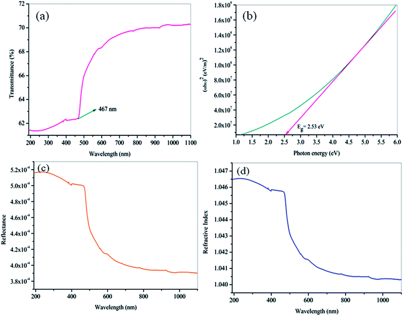
3.5 UV-visible transmission studies
For optical device applications, the lower absorption of light in the visible and good transparency window over a near IR wavelength range is an essential parameter for the NLO materials. To find the effective transparency range of the grown crystal, the optical transmittance spectrum of the HSPI has been recorded for the wavelength between 190 and 1100 nm using ELICO SL 218 double beam UV-vis-NIR spectrometer and is shown in Fig. 10a. From the spectrum, it is interesting to note that the HSPI crystal has good transparency in the vis-NIR region. The lower cut-off wavelength is found to be at 467 nm (π → π* transitions) in the visible region which explain the molecular electronic transitions from the ground state to excited energy states.22 Further, the λmax of HSPI is relatively lower compared with few other stilbazolium derivatives23,24 as given in Table 5. Hence, it is important for UV tunable laser, NLO, and optoelectronic device applications in its region of transmission.25
 |
| | Fig. 10 (a) Optical transmittance spectrum of HSPI crystal. (b) Plot of (αhν)2 vs. hν for HSPI crystal (c) plot of wavelength dependent reflectance. (d) Refractive index (n0). | |
Table 5 Comparison of λmax of HSPI with other stilbazolium derivatives
| Compound |
λmax (nm) |
| HSPI (present work) |
467 |
| DSHS |
474 |
| DAST |
475 |
| DSMOS |
476 |
| DSNS |
476 |
3.5.1 Energy band gap and refractive index calculation. The optical constants such as energy band gap (Eg), extinction coefficient (K) and refractive index (n0) is quite essential to examine the optical material for the fabrication of optical devices in a particular wavelength. Further, the optical constants are very closely related to the material's atomic structure, electronic band structure, and electrical properties.26,27 The photon energy dependence of the optical absorption coefficient (α) helps to study the band structure and the type of transition of electrons.28 From the transmittance spectra, the optical absorption coefficient (α) was calculated using the relation,| |
 | (1) |
where T is the transmittance and t is the thickness of the crystal. As an indirect band gap material, the optical absorption coefficient was calculated using the Tauc's expression| |
 | (2) |
where A is a constant and Eg is the optical band gap of the crystal. The optical band gap Eg of HSPI crystal was estimated by plotting hν vs. (αhν)2 (Fig. 10b) and the value was found to be 2.53 eV. The extinction coefficient explains the amount of absorption when electromagnetic wave propagates through a medium and can be found out using the relation,| |
 | (3) |
where, α is the absorption coefficient and λ is the wavelength of light. The reflectance (R) and refractive index (n0) in terms of the absorption coefficient can be derived from the relations:29,30| |
 | (4) |
| |
 | (5) |
Fig. 10c and d evidence the variation of reflectance (R) and the refractive index (n0) as a function of wavelength. It is noticed that the HSPI crystal has a photon energy-dependent refractive index (n0 = 1.040 at 1100 nm), and this reveals the focusing nature of the crystal. It also shows the sufficiently low values of refractive index and reflectance in the visible region. These factors enhance the HSPI crystal more suitable for calibrating the optical components such as resonators, signal filtering, and reflectors.31,32
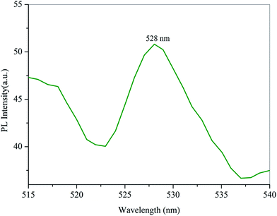
3.6 Photoluminescence studies
The photoluminescence spectrum of HSPI crystal was recorded with an input excitation wavelength of 467 nm using Cary Eclipse Fluorescence Spectrophotometer at room temperature. The emission spectrum was measured in the range from 480–600 nm. From the spectrum (Fig. 11), the maximum emission observed around λmax = 528 nm (2.34 eV) is assigned to the π → π* transitions between the donor (hydroxyl group) and acceptor (pyridinium ring) through the stilbazolium chromophore (–CHCH–) depicting green emission. Further, the weaker emission band in the green region (528 nm) adds the high purity and perfect crystallinity of the grown crystal.33 Hence, the PL study suggests that the defect-free, good crystals are expected for optoelectronic device applications, particularly in the green emission regime.
 |
| | Fig. 11 Emission spectrum of HSPI. | |
3.7 Thermal analysis
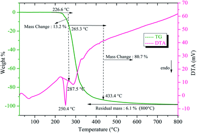
The thermogravimetric (TG) and differential thermal analysis (DTA) was carried out for the sample weight of 7.66 mg between room temperature and 800 °C at a heating rate of 10 °C min−1 in an argon atmosphere. From the TG curve (Fig. 12) it is noted that the decomposition of the title compound took place in two stages. The DTA replicates the same changes shown by the TG. It is observed that the title compound is stable up to 226.6 °C after which the first decomposition starts with a weight loss of 13.2% of the initial mass. The second stage of decomposition occurring between 265.3 °C and 433.4 °C incurs a major weight loss of about 80.7%. These weight losses are due to the complete decomposition of stilbazolium ions (both cation and anion) in the title crystal. The first sharp endothermic dip in DTA at 250.4 °C corresponds to the melting point of the crystal. The sharpness of this endothermic peak shows the high degree of crystallinity and purity of HSPI.34 The second endothermic dip at 287.5 °C indicates that the major decomposition of the substance, which coincides with the maximum weight loss occurring between 265.3 °C and 433.4 °C in the TG curve. At a temperature of about 800 °C, only 6.1% of the initial mass was obtained as residue. The observed melting point of HSPI is found to be slightly lower than that of DAST (258 °C) and show an improved thermal stability than few other stilbazolium derivatives like; EMSB (204 °C), HBST (237 °C) and DSPAS (241 °C).35–38 Thus the title compound could be exploited for realizing practical applications below 250.4 °C.
 |
| | Fig. 12 TG/DTA thermograms of HSPI. | |
3.8 Hardness studies
Microhardness is the measure of the strength of the material, and it is an important mechanical behaviour of the optical materials that are used for device fabrication. Transparent crystals with smooth surfaces of the crystal were subjected to hardness study at room temperature using an MH-112 Vicker's hardness tester with the diamond pyramidal indenter. The indentations were made for the applied loads (10, 25, 50 and 100 g) on the polished (010) face of HSPI while keeping the time of indentation at 10 s for all the cases. The microhardness number Hv of the crystal was calculated using the standard formula,| |
 | (6) |
where P is the applied load (kg) and d is the average diagonal length of the indentation (μm), which is measured by a calibrated microscope (MH-100). A graph plotted between Vickers hardness (Hv) versus load (P) is depicted in Fig. 13a. From the figure, it is observed that hardness value increases with increasing the load satisfying the reverse indentation size effect (RISE).39 Above 100 g cracks start developing which may be due to the release of internal stress generation with indentation.
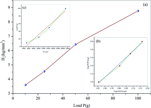 |
| | Fig. 13 (a) Variation of Vickers hardness Hv with load P (b) plot of logP vs. logd and (c) plot of load P vs. d2. | |
The Meyer index n (or work-hardening coefficient), is computed from logP versus logd plot (inset of Fig. 13b), which is determined to be 3.26 for the (010) plane respectively. Hence, the Meyer index value indicates shows the softness of the grown crystal satisfying Onitsch results.40 The obtained value of n (3.26) indicates that the HSPI crystal has a high mechanical strength and will be used in device applications.
In the present case, the yield strength of the material can be calculated from the hardness value (Hv) as Meyer's index was found to be 3.26 (n > 2) by the following relation
| |
 | (7) |
Also, the elastic stiffness constant (C11) was calculated using Wooster's empirical relation,41 which gives a broad idea about the interatomic bonding strength of materials. The load dependent hardness parameters of σy and C11 are compiled in Table 6.
Table 6 Values of yield strength and elastic stiffness constant of HSPI
| Load P (g) |
Yield strength σy (GN m−2) |
Elastic stiffness constant C11 (1014 Pa) |
| 10 |
0.556 |
0.161 |
| 25 |
0.702 |
0.243 |
| 50 |
0.993 |
0.445 |
| 100 |
1.564 |
0.767 |
The dependence of indentation size (d) on the applied indentation test load (P) are examined by Hays–Kendall approach by the relation42
where
W is the minimum load to initiate plastic (permanent) deformation in grams and
A1 is the load independent constant. These two values have been estimated by plotting a graph of
P vs. d2 for the loads 10–100 g as shown in the inset of
Fig. 13c. As the grown crystal exhibits reverse indentation size effect, the estimated value
W is found to be negative.
43 The corrected hardness value
H0 has been determined using the relation,
H0 = 1854.4
A1. The values of
W and
H0 are −26.66 g and 10.57 g μm
−2 respectively for HSPI crystal.
3.9 Dielectric studies
In the current scientific community, the dielectric based materials have widespread applications in the area of solid-state electronics.44 The variation of dielectric constant (εr) and the dielectric loss (tanδ) was studied as a function of frequency (50 Hz to 5 MHz) at different temperatures using an HIOKI 3532-50 LCR HiTESTER meter shown in Fig. 14a and b. The good transparent crystal of thickness 1.9 mm and area of cross section 15.75 mm2 with (010) face were subjected to dielectric studies and its opposite faces were coated with high-grade silver paste to ensure good electrical contact. The dielectric constant was calculated from the value of the capacitance of the sample using standard formula εr = Ct/ε0A. It is observed from the plot that the dielectric constant (εr) and dielectric loss (tanδ) decreases with increasing frequency and attains saturation at higher frequencies. The high value of εr and tanδ at lower frequency indicates the presence of contribution from all type of polarisation (i.e., electronic, ionic, orientation, and space charge polarisation).45,46 At higher frequencies, the dipoles cannot cope up with the varying external field and hence the εr decreases.47 Fig. 14b suggests that the dielectric loss is strongly dependent on the frequency of the applied field; the behaviour is similar to that of the dielectric constant. The characteristic of low dielectric constant and dielectric loss at higher frequencies reveal that the grown crystal possesses enhanced optical quality with lesser defects, which are necessary for various optical and photonic applications.48
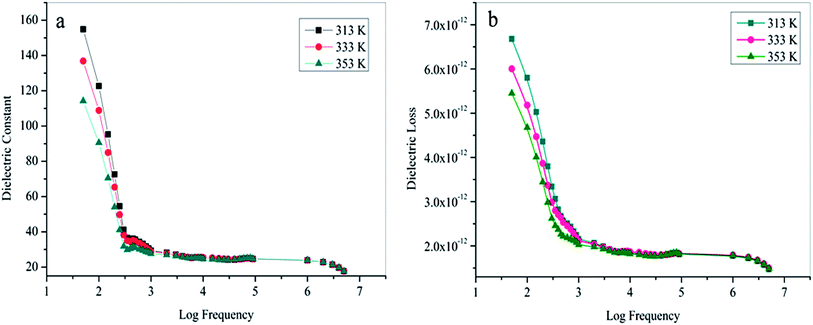 |
| | Fig. 14 Temperature dependence of (a) dielectric constant and (b) dielectric loss at various frequencies. | |
As in the reported literature,49,50 solid-state parameters like Penn gap, fermi energy and polarizability of the grown crystal have been calculated theoretically by taking into account its total number of valence electrons Z = 94, density ρ = 1.616 g cm−3, molecular mass M = 353.20 g mol−1 and the value of dielectric constant (εr) 23.86 at 1 MHz. The obtained parameters are listed in Table 7. The calculated electronic polarizability values are in agreement with the values derived from the Clausius–Mossotti relation.
Table 7 Theoretical data of polarizability on HSPI
| Parameters |
Values |
| Plasma energy (eV) |
18.887 |
| Penn gap (eV) |
3.950 |
| Fermi gap (eV) |
14.828 |
| Polarizability using Penn analysis (cm3) |
7.586 × 10⁻²³ |
| Polarizability using Clausius–Mossotti equation (cm3) |
7.663 × 10⁻²³ |
3.10 Chemical etching studies
Chemical etching is an elegant technique to study the structural defects and the crystal growth mechanism of the grown single crystal. Micro-morphology studies on (010) plane of the as-grown crystal of HSPI were carried out using methanol–acetonitrile etchant (1:1) for an etching time of 15 s and 30 s. Then the etched surfaces were dried gently, and the surfaces were examined by under Carl Zeiss optical microscope in the reflection mode (50× magnification). Fig. 15a represents the photomicrograph of as-grown crystal before etching. Rectangular etch pits are observed which shows the layer growth of the crystal after etching for 15 s in Fig. 15b. By increasing the etching time for 30 s (Fig. 15c), there is no change in the shapes, but the size of the pits slightly increased. The observed etch pits on the as-grown crystal surface implies that the crystal has layered growth with 2D nucleation mechanism and had fewer dislocations.51
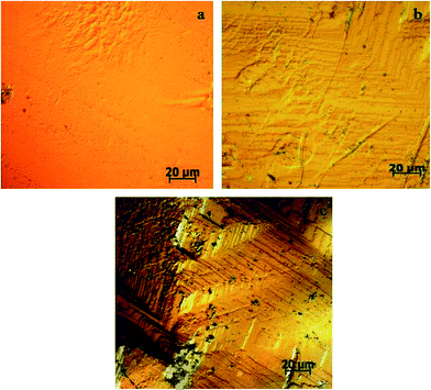 |
| | Fig. 15 Etch pattern on the HSPI crystal (a) before etching, (b) after etching for 15 s, (c) after etching for 30 s. | |
3.11 Laser damage threshold studies
Laser damage threshold of optical crystals are crucial as the surface damage of the crystal by high-power lasers limits its performance in device applications.52,53 In the present study, LDT measurement was carried out using a focused Q-switched Nd:YAG laser (1064 nm) along the (010) plane. For this measurement, the laser beam diameter of 0.8 mm with the repetition rate of 10 Hz having the pulse width of 10 ns was used. Controlled output laser intensity was allowed to fall on the crystal, which was positioned near the converging lens of focal length 30 cm. During laser irradiation, the coherent energy/power meter (model no. EPM 2000) records the input laser energy intensity at which the crystal gets damaged. The damage threshold was calculated using the expression| |
 | (9) |
where I is the energy density, E is the input energy in millijoule (mJ), τ is the pulse width (ns), and A is the area of the circular spot (mm), respectively. Thus, the laser damage energy density was measured 6.93 GW cm−2. An optical photograph of the damaged HSPI crystal by a laser beam is shown in Fig. 16. Further, the values are comparable with reported NLO crystals and are given in Table 8.54–56 Hence, the high damage threshold value reveal that the title material can withstand high-power laser intensity up to the tolerance of 6.93 GW cm−2.
 |
| | Fig. 16 Laser damage profile of HSPI. | |
Table 8 Laser damage threshold value of HSPI with reported NLO crystals
| Crystal |
Laser damage threshold (GW cm−2) |
| KDP |
0.2 |
| Urea |
1.5 |
| DAST |
2.8 |
| MMST |
3.9 |
| DSPTB |
4.3 |
| HSPI (present work) |
6.9 |
3.12 Z-scan studies
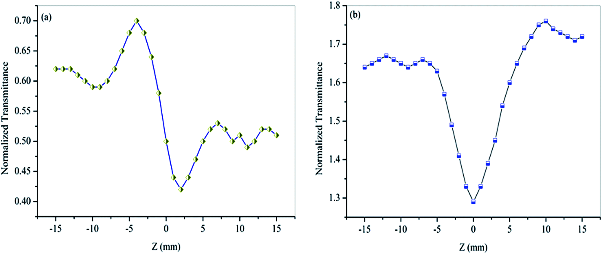
The third-order nonlinear behaviour of the material was investigated by the single beam Z-scan technique with the He–Ne laser of intensity 5 mW (λ = 632.8 nm). It is a standard technique for the simultaneous measurement of both the sign and magnitude of the nonlinear refractive index (n2) and the nonlinear absorption coefficient (β) by closed and open aperture mode respectively.57 In this study, the polarised laser beam is focused by a converging lens of 30 mm focal length to provide beam waist ω0 at the focus of 12.05 μm. Accordingly, the Rayleigh length ZR was calculated to be 0.72 mm, which is greater than the thickness of the crystal (0.65 mm). Hence, the thin-sample condition is satisfied in this measurement.58 The respective light transmission corresponding to the change in the Z-direction of the crystal has been measured through digital power meter (Field master GS coherent) placed in the far field. Measurements of the closed and open aperture of the normalized transmittance as a function of sample position Z have been made for HSPI crystal, and the curves are shown in Fig. 17a and b. In closed aperture pattern Fig. 17a, the curves are characterized by a prefocal maximum (peak) followed by a post-focal minimum (valley) intensity, evidences the negative sign of nonlinear refraction, i.e., the occurrence of self-defocusing.59 Here the defocusing nonlinearity is attributed to the process of thermally induced refractive index change. The open aperture curve Fig. 17b reveals that the transmittance of crystal gains minimum value at the focus (Z = 0). This is an indicative of Reverse Saturation Absorption (RSA), where the excited state absorption must be larger than that of the ground state.60
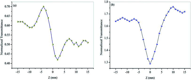 |
| | Fig. 17 Z-scan measurement of HSPI (a) closed aperture (b) open aperture. | |
The nonlinear refractive index (n2) and the nonlinear absorption coefficient (β) can be calculated using standard relations.61 The on-axis phase shift at the focus |ΔΦ0|, is related to the difference in the peak and valley transmission (ΔTp–v) in closed aperture trace as,
| | |
ΔTp–v = 0.406(1 − S)0.25|ΔΦ0|
| (10) |
where
S is the aperture in linear transmittance regime (
S = 0.52), and it can be calculated using the relation,
S = 1 − exp(−2
ra2/
ωa2). The on-axis phase shift is related to third-order nonlinear refractive index (
n2) of the crystal by
| |
 | (11) |
where
K is the wave number (
K = 2π/
λ),
I0 is the on-axis irradiance at focus (
Z = 0) (
I0 = 26.31 MW m
−2) and
Leff = [1 − exp(−
αL)]/
α] is the effective thickness of the crystal, where
α and
L are the linear absorption coefficient and the thickness of the crystal respectively.
The nonlinear absorption coefficient (β) can be estimated from the open aperture using the relation,
| |
 | (12) |
where Δ
T is the one valley value at the open aperture Z-scan curve. The value of
β will be negative for saturable absorption and positive for two-photon absorption.
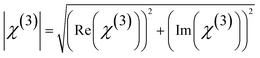
The absolute value of third order nonlinear optical susceptibility (χ(3)) is thus calculated by,
| |
 | (13) |
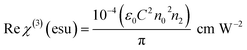
The real part of susceptibility is related to nonlinear refractive index (n2) through
| |
 | (14) |
The imaginary part of susceptibility is related to nonlinear absorption coefficient (β) through
| |
 | (15) |
where
ε0 is the permittivity of free space,
n0 is the linear refractive index of the crystal and
C is the velocity of the light in a vacuum.
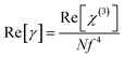
Further, the corresponding second-order hyperpolarizability γ is related to susceptibility by the equation62
| |
 | (16) |
where
N is the number density of molecules and
f is a local field correction ((
n02 + 2)/3).
Table 9 portrays the experimental details and the results of the Z-scan technique for HSPI crystal. The estimated nonlinear refractive index, nonlinear absorption coefficient, third-order susceptibility and second-order hyperpolarizability of HSPI is 7.29 × 10
−12 m
2 W
−1, 3.18 × 10
−4 m W
−1, 4.40 × 10
−4 esu and 6.52 × 10
−34 esu respectively. The third-order susceptibility is found to be comparably larger than the other well-known NLO crystals in
Table 10. Moreover, this may be due to the electron charge transfer between donor and acceptor, which results in strong polarization within the molecular structure leads to the higher value of (
χ(3)) and
γ in the title crystal.
63,64 Moreover, the defocusing nature of HSPI due to the negative refractive index may be the reason for high laser damage threshold value [6.93 GW cm
−2].
65 Thus, the HSPI could be utilized effectively for the protection of night vision optical sensors, optical power limiting devices and high power laser applications.
64
Table 9 Measurement details and results of the Z-scan technique
| Parameters |
Measured values for HSPI crystal |
| Laser beam wavelength (λ) |
632.9 nm |
| Lens focal length (f) |
30 mm |
| Optical bath length |
85 cm |
| Beam radius at the aperture (ωa) |
3.3 mm |
| Aperture radius (ra) |
2 mm |
| Sample thickness (L) |
0.65 mm |
| Incident intensity at the focus (I0) |
26.31 MW m−2 |
| Effective thickness (Leff) |
4.36 × 10⁻⁴ m |
| Nonlinear absorption coefficient (β) |
3.18 × 10⁻⁴ m W−1 |
| Nonlinear refractive index (n2) |
7.29 × 10⁻¹² m2 W−1 |
| Third-order nonlinear optical susceptibility (χ(3)) |
4.40 × 10⁻⁴ esu |
| Second order molecular hyperpolarizability (γ) |
6.52 × 10⁻³⁴ esu |
| Number of molecules per unit volume |
2.76 × 1027 m−3 |
Table 10 Comparison of χ(3) values of HSPI with other NLO materials
| Crystal |
Third order susceptibility (χ(3)) |
References |
| HSPI |
4.40 × 10⁻⁴ esu |
Present work |
| VSNS |
6.56 × 10⁻⁵ esu |
66 |
| 2APTC |
2.02 × 10⁻⁶ esu |
67 |
| VMST |
9.69 × 10⁻¹² esu |
5 |
4. Conclusion
Single crystals of stilbazolium derivative, 1-ethyl-2-[2-(4-hydroxy-phenyl)-vinyl]-pyridinium iodide (HSPI) with a dimension of 14 × 11 × 8 mm3 were successfully obtained by slow evaporation technique. The crystal structure and morphology of HSPI were examined by single crystal XRD. Spectroscopic analysis revealed the functional group present in the crystal. The optical transparency of the grown crystal lies between 468 nm and 1100 nm and it exhibits green fluorescence emission at 528 nm. Thermal analysis brings forth that the grown crystal melts at 250.4 °C and below that there is no phase transformation occurs. The grown crystal is mechanically stable up to 100 g, and its good dielectric behaviour confirms its applications in the field of organic optoelectronics, electro-optic modulators, and photonic devices. Theoretical calculations of polarizability, which are useful for device fabrication, were made using Clausius–Mossotti relation and Penn analysis agrees well with each other. The layered growth etch pattern are observed in etching studies. Third order nonlinear optical studies showed that the HSPI crystal possesses reverse saturation absorption and negative nonlinear refraction. The high LDT value (6.93 GW cm−2) is due to the self-defocusing nature of HSPI and thus favourable its usage for high power laser frequency applications. The high value of γ (6.52 × 10⁻³⁴ esu) and low value of HOMO–LUMO energy gap (0.76 eV) are an additional property of exhibiting the nonlinear optical property of the title crystal. Thus, all the findings of the various studies suggested that HSPI might be a prospective material for device fabrications in the field of nonlinear optical area.
Acknowledgements
The author would like to thank the VIT University management for their constant support and providing the excellent research facilities.
References
- D. Sajan, N. Vijayan, K. Safakath, R. Philip and H. Joe, J. Phys. Chem. A, 2011, 115, 8216–8226 CrossRef CAS PubMed.
- H. Rath, J. Sankar, V. PrabhuRaja, T. K. Chandrashekar, A. Nag and D. Goswami, J. Am. Chem. Soc., 2005, 127, 11608–11609 CrossRef CAS PubMed.
- J. P. Zou, Q. Peng, Z. Wen, G. S. Zeng, Q. J. Xing and G. C. Guo, Cryst. Growth Des., 2010, 10, 2613–2619 CAS.
- K. Clays and B. J. Coe, Chem. Mater., 2003, 15, 642–648 CrossRef CAS.
- M. K. Kumar, S. Sudhahar, P. Pandi, G. Bhagavannarayana and R. M. Kumar, Opt. Mater., 2014, 36, 988–995 CrossRef.
- M. González, J. L. Segura, C. Seoane and N. Martín, J. Org. Chem., 2001, 66, 8872–8882 CrossRef.
- K. Y. Suponitsky, Y. Liao and A. E. Masunov, J. Phys. Chem. A, 2009, 113, 10994–11001 CrossRef CAS PubMed.
- V. Krishnakumar and S. Muthunatesan, Spectrochim. Acta, Part A, 2006, 65, 818–825 CrossRef CAS PubMed.
- M. Jazbinsek, L. Mutter and P. Günter, Journal of Quantum Electronics, 2008, 14, 1298–1311 CrossRef CAS.
- C. Zhan, Y. Li, D. Li, D. Wang and Y. Nie, Opt. Mater., 2006, 2, 289–293 CrossRef.
- H. Ephard and P. Fromherz, J. Phys. Chem., 1989, 93, 7717–7725 CrossRef.
- L. M. Loew, S. Scully, L. Simpson and A. S. Waggoner, Nature, 1979, 281, 497–499 CrossRef CAS PubMed.
- W. Kaminsky, J. Appl. Crystallogr., 2005, 38, 566 CrossRef CAS.
- L. Farrugia, J. Appl. Crystallogr., 1997, 30, 565 CrossRef CAS.
- L. Pauling, The Nature of the Chemical Bond, Oxford University Press, London, 1960, p. 260 Search PubMed.
- X. H. Zhang, L. Y. Wang, G. H. Zhai, Z. Y. Wen and Z. X. Zhang, J. Mol. Struct., 2008, 881, 117–122 CrossRef CAS.
- B. Kosar and C. Albayrak, Spectrochim. Acta, Part A, 2011, 78, 160–167 CrossRef PubMed.
- Y. Sheena Mary, C. YohannanPanicker, B. Narayana, S. Samshuddin, B. K. Sarojini and C. Van Alsenoy, Spectrochim. Acta, Part A, 2014, 133, 480–488 CrossRef CAS PubMed.
- Wavefunction, Inc., 18401 Von Karman Ave., Suite 370, Irvine, CA 92612.
- N. Okulik and A. H. Jubert, Internet Electron. J. Mol. Des., 2005, 4, 17–21 CAS.
- R. Jerald Vijay, N. Melikechi, T. Thomas, R. Gunaseelan, M. Antony Arockiaraj and P. Sagayaraj, Mater. Chem. Phys., 2012, 132, 610–617 CrossRef.
- S. Kasap and P. Capper, Springer Handbook of Electronic and Photonic Materials, Springer Science Inc., 2006, pp. 47–69 Search PubMed.
- Z. Yang, S. Aravazhi, A. Schneider, P. Seiler, M. Jazbinsek and P. Günter, Adv. Funct. Mater., 2005, 15, 1072–1076 CrossRef CAS.
- K. Senthil, S. Kalainathan and A. Ruban Kumar, CrystEngComm, 2014, 16, 9847–9856 RSC.
- S. Venkataramanan, S. Maheswaran, J. N. Sherwood and H. L. Bhat, J. Cryst. Growth, 1997, 179, 605–610 CrossRef.
- M. Dongol, Egypt J. Solid., 2002, 25, 33–47 Search PubMed.
- R. N. Rai, S. R. Mudunuri, R. S. B. Reddi, V. S. A. K. Satuluri, S. Ganeshmoorthy and P. K. Gupta, J. Cryst. Growth, 2011, 321, 72–77 CrossRef CAS.
- N. Tigau, V. Ciupinaa, G. Prodana, G. I. Rusub, C. Gheorghies and E. Vasilec, J. Optoelectron. Adv. Mater., 2004, 6, 211 CAS.
- R. Robert, C. Justin Raj, S. Krishnan and S. Jerome Das, Phys. B, 2010, 405, 20–24 CrossRef CAS.
- M. A. Kaid and A. Ashour, Appl. Surf. Sci., 2007, 253, 3029 CrossRef CAS.
- E. F. Schubert, J. K. Kim and J. Q. Xi, Phys. Status Solidi B, 2007, 244, 3002–3008 CrossRef CAS.
- M. Anis, S. S. Hussaini, A. Hakeem, M. D. Shirsat and G. G. Muley, Optik, 2016, 127, 2137–2142 CrossRef CAS.
- S. Sudhahar, M. Krishna Kumar, B. N. Sornamurthy and R. Mohan Kumar, Spectrochim. Acta, Part A, 2014, 118, 929–937 CrossRef CAS PubMed.
- A. H. Hameed, G. Ravi, R. Dhanasekaran and P. Ramasamy, J. Cryst. Growth, 2000, 212, 227–232 CrossRef.
- Y. W. Chen-Yang, T. J. Sheu, S. S. Lin and Y. K. Tu, Curr. Appl. Phys., 2002, 2, 349–353 CrossRef.
- A. S. Gill and S. Kalainathan, J. Phys. Chem. Solids, 2011, 72, 961–967 CrossRef.
- K. Jagannathan, S. Kalainathan and G. Bhagavannarayana, Spectrochim. Acta, Part A, 2009, 73, 79–83 CrossRef CAS PubMed.
- Z. Yang, M. Jazbinsek, B. Ruiz, S. Aravazhi, V. Gramlich and P. Gunter, Chem. Mater., 2007, 19, 3512–3518 CrossRef CAS.
- J. Gong and Y. Li, J. Mater. Sci., 2000, 35, 209–213 CrossRef CAS.
- S. Mukerji and T. Kar, Cryst. Res. Technol., 1999, 34, 1323 CrossRef CAS.
- W. A. Wooster, Rep. Progr. Phys., 1953, 16, 62–82 Search PubMed.
- C. Hays and E. G. Kendall, Metallography, 1973, 6, 275–282 CrossRef CAS.
- K. Sangwal, M. Hordyjewicz and B. Surowska, J. Optoelectron. Adv. Mater., 2002, 4, 875–882 CAS.
- N. Rani, N. Vijayan, B. Riscob, S. K. Jat, A. Krishna, S. Das, G. Bhagavannarayana, B. Rathi and M. A. Wahab, CrystEngComm, 2013, 15, 2127–2132 RSC.
- N. Kumar, A. Ghosh and R. N. P. Choudhary, Mater. Chem. Phys., 2011, 130, 381–386 CrossRef CAS.
- S. Alen, D. Sajan, K. Job Sabu, K. Udaya Lakshmi, V. Veeraiah, K. Chaitanya and V. Bena Jothy, CrystEngComm, 2013, 15, 9176 RSC.
- B. B. Parekh and M. J. Joshi, Cryst. Res. Technol., 2007, 42, 127–132 CrossRef CAS.
- C. Balarew and R. Duhlev, J. Solid State Chem., 1984, 55, 1–6 CrossRef.
- K. M. Chauhan and S. K. Arora, Cryst. Res. Technol., 2009, 44, 189–196 CrossRef CAS.
- K. Thukral, N. Vijayan, B. Rathi, G. Bhagavan Narayana, S. Verma, J. Philip, A. Krishna, M. S. Jeyalakshmy and S. K. Halder, CrystEngComm, 2014, 16, 2802–2809 RSC.
- T. Mukerji and J. Kar, J. Cryst. Growth, 1999, 204, 341 CrossRef.
- G. C. Bhar, A. K. Chaudhary and P. Kumbhakar, Appl. Surf. Sci., 2000, 161, 155–162 CrossRef CAS.
- A. Krishna, N. Vijayan, S. Gupta, K. Thukral, V. Jayaramakrishnan, B. Singh, J. Philip, S. Das, K. K. Maurya and G. Bhagavannarayana, RSC Adv., 2014, 4, 56188–56199 RSC.
- S. A. Martin Britto Dhas and S. Natarajan, Cryst. Res. Technol., 2007, 42, 471–476 CrossRef.
- M. K. Kumar, S. Sudhahar, A. Silambarasan, B. M. Sornamurthy and R. M. Kumar, Optik, 2014, 125, 751–755 CrossRef CAS.
- K. Senthil, S. Kalainathan, F. Hamada and Y. Kondo, RSC Adv., 2015, 5, 79298–79308 RSC.
- M. Sheik-Bahae, A. A. Said, T. H. Wei, D. J. Hagan and E. W. Van Stryland, Journal of Quantum Electronics, 1990, 26, 760–769 CrossRef CAS.
- T. Jia, T. He, P. Li, Y. Mo and Y. Cui, Opt. Laser Technol., 2008, 40, 936–940 CrossRef CAS.
- S. Shettigar, G. Umesh, K. Chandrasekaran and B. Kalluraya, Synth. Met., 2007, 157, 142–146 CrossRef CAS.
- F. Z. Henari and P. S. Patil, Opt. Photonics J., 2014, 4, 182–188 CrossRef CAS.
- R. L. Sutherland, Handbook of Nonlinear Optics, Marcel Dekker Inc., New York, 1996 Search PubMed.
- Q. Gong, Y. Sun, Z. Xia, Y. H. Zou, Z. Gu, X. Zhou and D. Qiang, J. Appl. Phys., 1992, 71, 3025–3026 CrossRef CAS.
- A. Antony Raj, R. Gunaseelan and P. Sagayaraj, Opt. Mater., 2014, 38, 102–107 CrossRef CAS.
- Y. S. Zhou, E. B. Wang, J. Peng, J. Liu, C. W. Hu, R. D. Huang and X. You, Polyhedron, 1999, 18, 1419–1423 CrossRef CAS.
- T. C. Girisun and S. Dhanuskodi, Cryst. Res. Technol., 2009, 44, 1297–1302 CrossRef CAS.
- K. Senthil, S. Kalainathan, A. Rubankumar and P. G. Aravindan, RSC Adv., 2014, 4, 56112–56127 RSC.
- P. V. Dhanaraj, N. P. Rajesh, G. Vinitha and G. Bhagavannarayana, Mater. Res. Bull., 2011, 46, 726–731 CrossRef CAS.
|
| This journal is © The Royal Society of Chemistry 2016 |
Click here to see how this site uses Cookies. View our privacy policy here.