DOI:
10.1039/C6RA01973K
(Paper)
RSC Adv., 2016,
6, 16859-16867
Nano iron pyrite (FeS2) exhibits bi-functional electrode character†
Received
22nd January 2016
, Accepted 2nd February 2016
First published on 3rd February 2016
Abstract
Sustainable charge storage devices require materials that are environmentally benign, readily moldable, easily synthesizable, and profitable for applications in the electronics industry. Nano iron pyrite (FeS2) is one such material, which is applicable in diverse areas like photovoltaic devices to seed dressing in agriculture. In this work, we propose an innovative application of nano FeS2viz., as a symmetric charge storage device that is flexible, portable, and lightweight; along with its fabrication details. The device consists of a (H3PO4)/polyvinyl alcohol (PVA) electrolyte gel sandwiched between two similar electrodes made up of FeS2/poly-aniline (PA), upon which graphite sheets are used as current collectors. Electrodes were characterized by XRD, FTIR and SEM. The device was calibrated by cyclic voltammetry and charge–discharge cycle. In its present laboratory prototype form, it powers solid-state electronic devices and electric motors. Further refinements of this device will open up new avenues in the field of sustainable charge storage devices and low power electronics.
1. Introduction
There is an ever-increasing demand in the energy sector for compact, lightweight, portable, economical and environmental friendly charge storage devices. Charge storage devices are broadly classified as batteries, capacitors and super-capacitors.1,2 The basic differences between these devices are in their energy storage potential, power density and cycle time.3
Current battery and super-capacitor manufacturers use a wide range of materials in combination. This includes sulfur-rich cathodes,4 lithium polysulfide,4 lithium nitrate,5 sodium sulfide,5 composite electrodes,3,5–7 conducting polymers,8 solid polymer electrolytes,8–10 organic electrolytes10,11etc. Many of these materials are inherently toxic, highly reactive and cost prohibitive.11,12 Thus there is always a quest for cheap, abundant and non-toxic materials for developing next generation of charge storage devices.13–17
Here we have developed a flexible, portable, light-weight charge storage device using nano iron pyrite (FeS2). FeS2 in its bulk form is an earth abundant mineral.18–21 It is an environmentally benign compound.21 It is readily and economically synthesized in nano-dimension, at a relatively low temperature.22–24 Nano FeS2 has been explored as a potential photo-voltaic material and as a seed dressing agent in agriculture.19,21–23,25 Nano FeS2 has an effective electron density around 3 × 1018 cm−3, intrinsic resistivity around 0.18 Ω cm, carrier mobility around 300 cm2 V−1 s−1, atomic packaging density around 7.55 × 10²² atoms per cm3 and charge storage capacity of around 900 mA h g−1.18–21,26–28 Lithium ion battery manufacturers use it as a counter electrode.29 In quest for cheap, abundant and non-toxic materials for developing next generation of charge storage devices,13–17 we explore the possibility of developing a charge storage device using nano FeS2. In this work, we are reporting the stepwise protocol for fabrication and characterization of a new kind of a flexible, symmetric charge storage device using nano FeS2, where (FeS2) exhibits bi-functional electrode character.
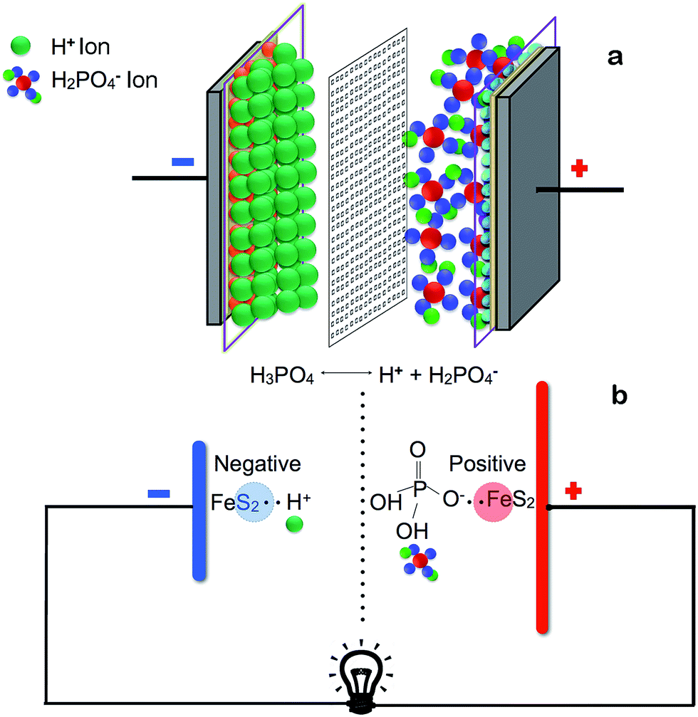
Why we used nano FeS2? FeS2 as such comprise of one electro-positive metal (Fe) with highly polarizable soft electro-negative sulfur atom. This will lead to a residual charge separation showing appreciable electro-positive character on iron and electro negative character on sulfur as well. Alignment of this charge distribution is selective, where if it function as a nucleophile then under a nano-surface the sulfur part will act as a nucleophile. Similarly its role of electrophile will be automatically decided by the iron atom to embrace the approaching nucleophile. Thus under optimum condition an electrolyte can impose such polarization so that the two faces of nano FeS2, may develop amphiphilic character. So a dissociable ionic electrolyte may allow its two ends, that is a cation and an anion to separate accordingly utilizing the nucleophilic and electrophilic heads of the nano FeS2. Thus we propose that this unique feature of nano FeS2 can be exploited to develop a bi-functional electrode to construct an electromotive cell. Fig. 1 describes the proposed device architecture.
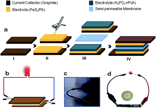 |
| | Fig. 1 Architecture and assembly of the prototyped charge storage device. (a) Preparation flow of charge storage device. (i) Two graphite sheets as current collectors. (ii) FeS2/Poly-aniline composite spray painted using an air brush onto the graphite sheets for making the electrodes. (iii) The electrolyte gel (phosphoric acid + polyvinyl alcohol) is placed on top of the electrodes. (iv) Charge storage device assembly having a semi-permeable membrane between the gel faces. (b) A schematic representation of a functional charge storage device with symmetric nano FeS2/PA electrodes connected to an LED. (c) Demonstrating flexibility property of the prototype. (d) Size comparison of actual charge storage device (three devices connected in series) with a standard coin. | |
2. Experimental section
2.1. Synthesis of FeS2 nanoparticles
The major raw material for the device is nano iron pyrite. In this Section we described the nano FeS2 synthesis. Multiple approaches are available for synthesis of FeS2, where almost all of them require high temperature, yet few synthesis techniques utilize low temperature strategy.22–24 A recent hot-injection based approach has successfully demonstrated FeS2 synthesis at a temperature of 200 °C.24 We developed a two-step method, which is slightly more complicated than the hot injection method, but can reduce the synthesis temperature to 100 °C. In the first step, we synthesized the polysulfide solution. In the second step, we use the polysulfide to synthesize the FeS2 particles. Briefly the synthesis was based upon the nucleophilic reaction between polysulfide and FeCl3 in an inert atmosphere at 100 °C, which resulted in the formation of FeS2 nanoparticles with uniform morphology. During the course of this reaction, FeS and FeSH+ species were formed, which reacted with polysulfide nucleophile thus leading to the formation of FeS2.22,23 The complete synthesis of nano FeS2 is given in ESI section (Fig. S1†).
2.2. Electrolyte preparation and electrode fabrication
The synthesized nano FeS2 particle powder color was grayish black. Now the base material is ready to make electrode material. So next, we developed the FeS2/poly-aniline (PA) composite electrode by chemically polymerizing the monomers of aniline in the presence of FeS2 nanoparticles in an aqueous suspension.5 The detailed description of preparation is given in ESI and illustrated in Fig. S2.† After synthesis, we got the brownish precipitate, which was the composite of FeS2 and poly-aniline (PA). PA electrodes were prepared by the same process as described above, without addition of FeS2.5,30,31 The electrolyte chosen for our charge storage device was a bio-compatible one, viz., phosphoric acid (H3PO4). H3PO4 is a weak acid that disassociates into H+ and H2PO4− ions. Poly-vinyl alcohol (PVA) was added to H3PO4 to create the polymeric-gel matrix that enables maximum entrapment of H3PO4 molecules; allowing ionic transportation with long time sustainability.8–10 Gel electrolyte offers flexibility by retaining maximum fluid in its pores, thereby significantly reducing the evaporation rate; prolonging the functional life of the prototype. The detailed preparation schematic is provided in the ESI section (Fig. S2†).
2.3. Assembling the device
Fig. 1a details the assembly of the device. The outer current collectors are made of two identical graphite sheets, which are flexible, having high thermal and electrical conductivity, possess chemical inertness, and has high refractory index. The dried FeS2/PA which was synthesized for electrodes was deposited on one side of graphite sheets using spray painting guns. To facilitate the spraying process, 30 mg of FeS2/PA was taken and mixed with 3 ml of isopropyl alcohol and 30 μl diluted (6×) Nafion solution, which was sonicated for four hours. The coating surface area was 2 cm2 of the graphite sheets, as shown in Fig. 1a(i and ii). The electrolyte gel formed from phosphoric acid + polyvinyl alcohol gel (PVA/H3PO4) was poured and casted on top of the electrodes and left undisturbed for duration of four hours at a temperature around 25 °C. Two such electrodes and electrolyte assembly were prepared. Then these graphite sheets were assembled with the gel layers facing each other, while being separated by a cellulosic semi-permeable membrane, as shown in Fig. 1a(iii). The final assembly of the device is depicted in Fig. 1a(iv). Initially the device had no polarity, and it acquired its positive and negative terminals after its first charging. The terminal that was connected to the positive terminal of the source becomes positive and vice versa.
2.4. Structural characterization of the electrodes
The FeS2/PA electrodes were characterized by X-ray diffraction (XRD), Fourier transform infrared spectroscopy (FTIR), Raman spectroscopy and scanning electron microscopy (SEM) techniques. XRD pattern of FeS2 exhibited the diffraction peaks at 28.71, 33.05, 37.09, 40.73, 47.40, 56.18, 61.53 and 64.22; which were indexed to (111), (200), (210), (211), (220), (311), (222) and (023) planes respectively (Fig. 2a). This was consistent with single phase of FeS2 (JCPDS card no. 42-1340) and indexed to space group Pa3 [205], that showed the cubic structure. No additional peak was observed in the XRD pattern thereby confirming the purity of the synthesized FeS2 sample.22,23,32–35 Similar peaks were observed in the diffraction pattern of FeS2/PA, thus indicating that the while the polymerization of poly-aniline took place, the FeS2 particles were not dissolved in the acidic medium. By the Scherrer's equation (D = Kλ/B![[thin space (1/6-em)]](https://www.rsc.org/images/entities/char_2009.gif) cosθ), (where λ = wave length of X-ray, θ the diffraction angle, K the shape factor and B = Bactual = √(Bobserved2 − Bresolution2) is the correct half width of the observed half width) the average crystalline size was calculated to be 35 nm. In FTIR spectra (Fig. 2b), the FeS2 powder exhibited a broad band centered at 3415 cm−1 and at 1615 cm−1, which could be assigned to the O–H stretching and bending modes of water, respectively. The bands at 1420 cm−1 and 1355 cm−1 corresponds to the asymmetric S–O stretching of the sulfate species while the peaks at 612 cm−1 and 410 cm−1 were characteristic of the disulfide stretch (S–S). For the FeS2/PA composite, band at 3380 cm−1 and 1530 cm−1 could be corresponding to O–H stretching and bending mode of water respectively. The band at 1420 cm−1 could be S–O stretching of sulfite species and 403 cm−1 would be disulfide (S–S) stretch. The band at the characteristic peaks at 1295 cm−1 and 1225 cm−1 could be corresponding to the quinoid ring (Q) and the benzene ring, respectively. The characteristic band of poly-aniline base will be the N
cosθ), (where λ = wave length of X-ray, θ the diffraction angle, K the shape factor and B = Bactual = √(Bobserved2 − Bresolution2) is the correct half width of the observed half width) the average crystalline size was calculated to be 35 nm. In FTIR spectra (Fig. 2b), the FeS2 powder exhibited a broad band centered at 3415 cm−1 and at 1615 cm−1, which could be assigned to the O–H stretching and bending modes of water, respectively. The bands at 1420 cm−1 and 1355 cm−1 corresponds to the asymmetric S–O stretching of the sulfate species while the peaks at 612 cm−1 and 410 cm−1 were characteristic of the disulfide stretch (S–S). For the FeS2/PA composite, band at 3380 cm−1 and 1530 cm−1 could be corresponding to O–H stretching and bending mode of water respectively. The band at 1420 cm−1 could be S–O stretching of sulfite species and 403 cm−1 would be disulfide (S–S) stretch. The band at the characteristic peaks at 1295 cm−1 and 1225 cm−1 could be corresponding to the quinoid ring (Q) and the benzene ring, respectively. The characteristic band of poly-aniline base will be the N![[double bond, length as m-dash]](https://www.rsc.org/images/entities/char_e001.gif) QN stretching band at 1128 cm−1.5,32–35 Raman spectrum was recorded in wave numbers ranging from 200 cm−1 to 500 cm−1 (ESI Fig. S3†). Sharp peaks were observed at 337 cm−1, 378 cm−1, and 431 cm−1; which is in agreement with published Raman spectroscopic results for pure FeS2 crystals.32–35 From the XRD, Raman Spectroscopy and FTIR it could be concluded that synthesized FeS2 possess single-phase pyrite without detectable marcasite, greigite, pyrrhotite, or other impurities. In SEM analysis of FeS2, it exhibited a pseudo octahedral or flowery morphology with an average particle diameter of 400–500 nm (Fig. 2c). We observed similar morphologies of FeS2 nanostructures in our earlier work.22,23Fig. 2d provides the SEM image of the poly-aniline. The poly-aniline exhibited a rod or tubular morphology with an average thickness of 20–30 nm. Fig. 2e showed the representative SEM picture of FeS2/PA composite. We observed that the sharp feature of FeS2 is missing. Instead we observed a more globular morphology. It seems as if the poly-aniline has encapsulated the FeS2 particles and offered them a more smooth and rounded texture and morphology respectively. Thus we have speculated that PA is forming a coating on the FeS2 surface thereby enhancing the electrochemical activity/conductivity of the composite (Fig. 2f).
QN stretching band at 1128 cm−1.5,32–35 Raman spectrum was recorded in wave numbers ranging from 200 cm−1 to 500 cm−1 (ESI Fig. S3†). Sharp peaks were observed at 337 cm−1, 378 cm−1, and 431 cm−1; which is in agreement with published Raman spectroscopic results for pure FeS2 crystals.32–35 From the XRD, Raman Spectroscopy and FTIR it could be concluded that synthesized FeS2 possess single-phase pyrite without detectable marcasite, greigite, pyrrhotite, or other impurities. In SEM analysis of FeS2, it exhibited a pseudo octahedral or flowery morphology with an average particle diameter of 400–500 nm (Fig. 2c). We observed similar morphologies of FeS2 nanostructures in our earlier work.22,23Fig. 2d provides the SEM image of the poly-aniline. The poly-aniline exhibited a rod or tubular morphology with an average thickness of 20–30 nm. Fig. 2e showed the representative SEM picture of FeS2/PA composite. We observed that the sharp feature of FeS2 is missing. Instead we observed a more globular morphology. It seems as if the poly-aniline has encapsulated the FeS2 particles and offered them a more smooth and rounded texture and morphology respectively. Thus we have speculated that PA is forming a coating on the FeS2 surface thereby enhancing the electrochemical activity/conductivity of the composite (Fig. 2f).
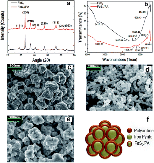 |
| | Fig. 2 Characterization of the electrode. (a) XRD of FeS2 and FeS2/PA. (b) FTIR of FeS2 and FeS2/PA. (c) SEM images of FeS2 showed pseudo octahedral flowery morphology. (d) SEM image of PA showed rod or tubular morphology. (e) SEM images of FeS2/PA have missing sharp feature of FeS2, instead showed more globular morphology. (f) Poly-aniline encapsulation on the FeS2 particles. | |
2.5. Electrochemical characterization of the device
The electrochemical characterization of the device was performed using electrochemical work station ‘Epsilon BASi Cell Stand C3’. The charge–discharge measurements were performed using AutolabB.V (Metrohm). The working electrode was of FeS2/PA with 1 cm2 area which was sprayed on one side of the graphite sheet. Only FeS2/PA area was activated as an electrode, remaining graphite sheet was kept as electrochemically insulated. The reference electrode was an Ag/AgCl (in 3 mol l−1 NaCl) electrode and the counter electrode was a platinum wire. CV was done at different scan rate from 5 mV s−1 to 300 mV s−1 at 0 to 0.8 V voltage window in aqueous 2 M H3PO4 solution.
3. Results and discussion
3.1. Rational for developing FeS2/PA composite electrode and gel electrolyte
The two electrodes were prepared by a FeS2/poly-aniline (PA) composite. Our rational for developing FeS2/PA composite electrode is the following: PA has been extensively studied as cathode material for electrochemical capacitor due to its excellent conductivity, redox reversibility and its stability towards environment.3,5,36–43 But one of the major drawbacks of using PA as stand alone electrode in the charge storage device is its poor discharge capacity.38,39,42 On the other hand iron disulfide (FeS2), one of the most abundant metal sulfide found on earth's crust, have three basic properties which are of immense significance for developing charge storage devices19–21,40,41,44,45viz., (a) mediating electron-transfer (b) electrical-charge separation, (c) capability to store energy temporarily or in the form of stable chemical products. Here we have shown that using a low temperature strategy we could obtain uniform size particles of FeS2. Thus marrying FeS2 with PA in the form of a composite could offer added benefit in terms of charge storage and discharge potential. That inspired us to create FeS2/poly-aniline composite. Further CV analysis showed that this strategy indeed mutually improved the charge storage and discharge capacity of both FeS2 and PA. Further it has been observed that the presence of nanoparticles in the matrix of the conducting polymer results in enhanced electrochemical activity/conductivity.43 The rational for choosing gel electrolyte was to ensure that the solution does not dry out easily and offer more flexibility to the device. The H3PO4 is reasonably biocompatible and also functions as an ionic liquid. Poly-vinyl alcohol (PVA) acts as a polymeric matrix thus simultaneously allowing ionic transport and functioning as a separator layer between the electrodes.46
3.2. Cyclic voltammetry (CV) analysis of the FeS2, PA & FeS2/PA electrodes and reason to select FeS2/PA for developing the device
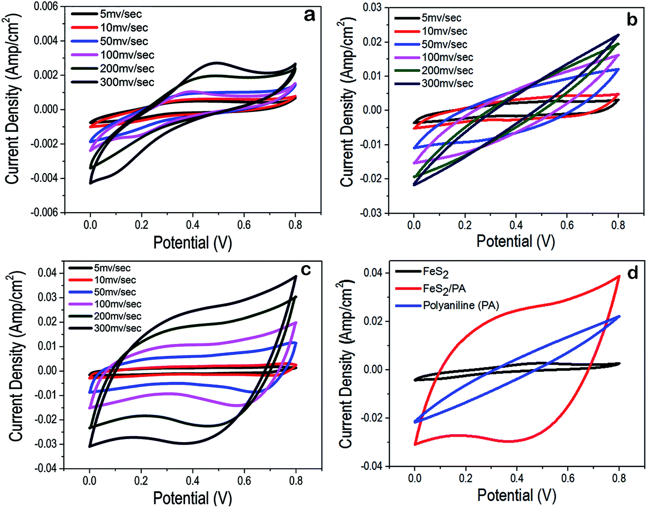
To evaluate the electrochemical performance of the FeS2, PA and FeS2/PA electrodes, cyclic voltammetry was carried out using Epsilon Basi C3 cell stand with conventional three electrode configuration in 2 M aqueous solution of H3PO4. CV was done at different scan rate from 5 mV s−1 to 300 mV s−1 at 0 to 0.8 V voltage window. Cyclic voltammogram of FeS2/PA had approximately rectangular shape as compared to the FeS2 and PA alone (Fig. 3a–c). FeS2/PA showed higher specific capacitance, as compared to FeS2 and PA alone. When the integrated area from CV from the voltammogram of FeS2, PA and FeS2/PA, we observed that FeS2/PA covers 14 times higher area as compared to FeS2 and 7 times higher area as compared to PA, thus highlighting the fact that FeS2/PA has highest specific capacitance as compared to the individual components (Fig. 3d). Correspondingly the current density was almost 15 times higher in FeS2/PA as compared to FeS2 alone and 2 times higher than PA (at a scan rate of 300 mV s−1) (Fig. 3d). Another interesting aspect of the CV of FeS2 is the following: in Fig. 3a we observed a significant hump at 0.2 and 0.4 V thus indicating that certain redox reaction is taking place, thus resulting in the pseudo capacitance as well as double layer capacitance. In Fig. 3b, in CV of PA, we observed that there is no hump but the area of curve and peak current is significantly higher than FeS2. Surprisingly in phosphoric acid environment, PA is not exhibiting observable pseudo-capacitance, whereas double layer capacitance is distinctly observable.39,42,46 Now in the Fig. 3c and d, CV of FeS2/PA showed small humps at 0.2 and 0.4 V, thus hinting at the occurrence of redox reaction. The FeS2/PA has specific capacitance approximately 362 F g−1 m−1 whereas the FeS2 have 112 F g−1 m−1. Thus addition of PA along with FeS2 improves the electrochemical properties of the electrode. Now, on the basis of the CV analysis, it was clear that FeS2/PA could perform as a better charge storage module as compared to FeS2 and PA alone. Thus we fabricated a FeS2/PA hybrid device and performed an electrochemical and charge/discharge characterization of the device (Fig. 4).
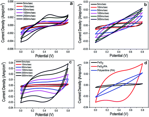 |
| | Fig. 3 CV analysis of electrode material. (a) CV of FeS2 at different scan rates. (b) & (c) CV of PA and FeS2/PA at same scan rates as seen in FeS2. (d) Comparison of the specific capacitance of FeS2 and FeS2/PA through CV at 300 mV s−1 scan rate. | |
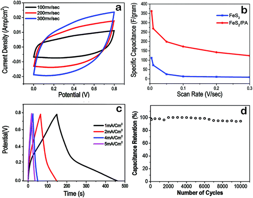 |
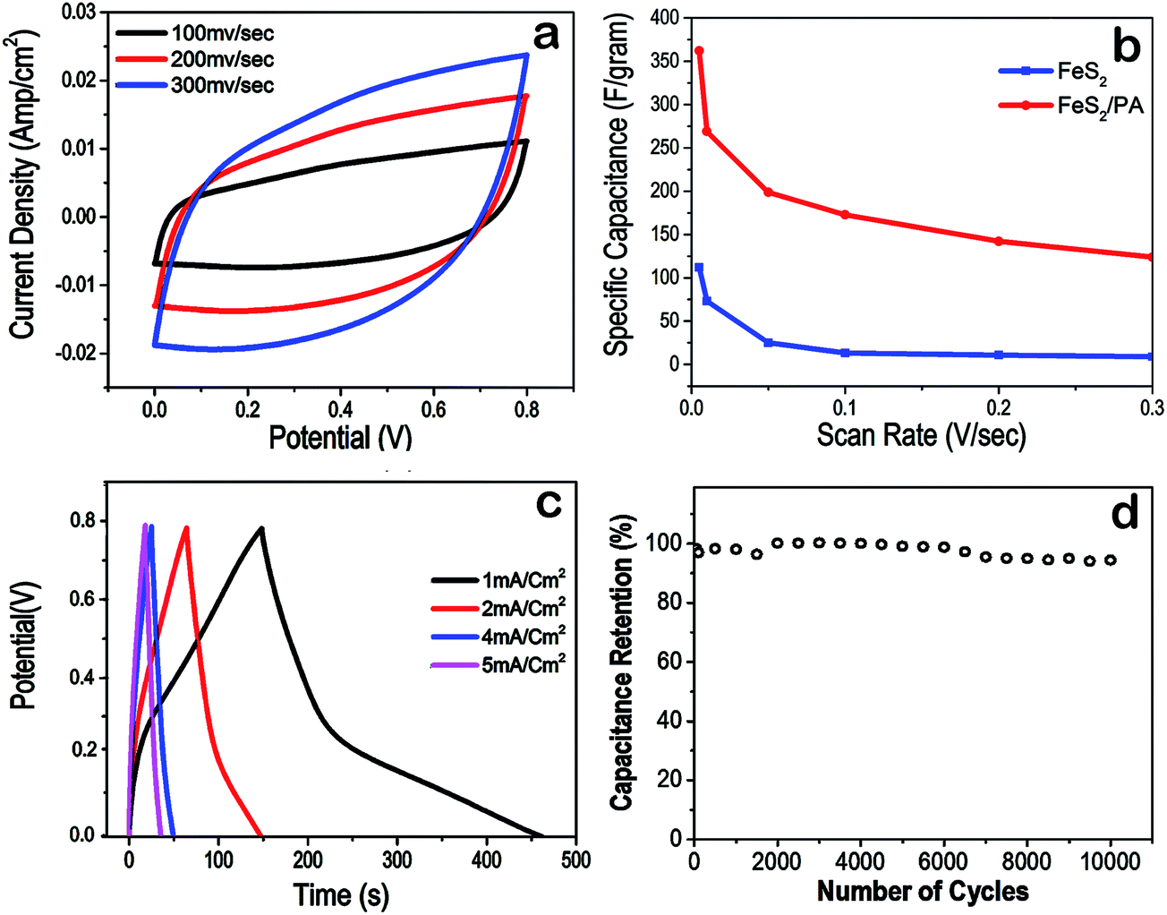
| | Fig. 4 Device characterization (a) CV of the device at different scan rate. (b) Relation between scan rate and specific capacitance. (c) Charge–discharge cycle of FeS2/PA device at different current density. (d) Percentage capacitance retention vs. number of cycles to validate stability and performance of the prototype device till 10000 charge–discharge cycles. | |
3.3. Electrochemical analysis of charge storage device
Further, cyclic voltammogram the charge storage device of FeS2/PA was performed. CV at different scan rate from 100 mV s−1 to 300 mV s−1 and 0 to 0.8 V voltage window showed that the graph was almost rectangular in all scan rates and current density was approximately 0.025A cm−2 for 300 mV s−1 (Fig. 4a). The specific capacitance (Cs) were calculated from the CV curves by equation
| (Cs = ∫I(u)dt/m × v × ΔV) |
where, m indicates the mass of the active electrode material, I is the oxidation or reduction current, v is the scan rate, dt is time differential, and ΔV indicates the voltage range of one sweep segment.6 It is observed that the specific capacitance decreased with an increase in the scan rate from 5 mV s−1 to 500 mV s−1 (Fig. 4b). This is possibly due to the insufficient time available for ion diffusion at faster scan rate. Galvanostatic charge–discharge characteristics of the device were performed using Autolab (NOVA 1.10 interface) at different current densities (1 mA cm−2, 2 mA cm−2, 4 mA cm−2 and 5 mA cm−2). The observed discharge curves of the device exhibited an almost mirror symmetry with its charge counterpart at higher current density such as 5 mA cm−2 (Fig. 4c). Interestingly as the current density decreased, the charge time became less and discharge time became high as could be seen in 1 mA cm−2 curve. In terms of values, the charge and discharge time is same for 5 mA cm−2 that is 20 s but for 1 mA cm−2 the charging time is 160 seconds but the discharging time 310 seconds. This means that the device could store charges for longer period of time. The thing which is noteworthy was that for low current density (4 mA cm−2 downwards), the discharge curve shows some flatness after 0.25 to 0.3 V. This flatness indicates that the charge storage device could hold charge in usable voltage range for a significant amount of time. The specific capacitance for the electrodes could be obtained from charge–discharge data by equation
where C (F g−1) is the specific capacitance, I (A) is the constant discharging current, Δt (s) is the discharging time, ΔV (V) is the potential window, and m (g) is the mass loading of the active material in the working.6 The specific capacitances of the FeS2/PA electrode are 390, 220, 125 and 113 F g−1 at the current densities of 1, 2, 4 and 5.0 mA cm−2, respectively. It can be seen here, that the specific capacitance values decreased with increasing current density.
3.4. Evaluating the functional stability of the electrodes and the device
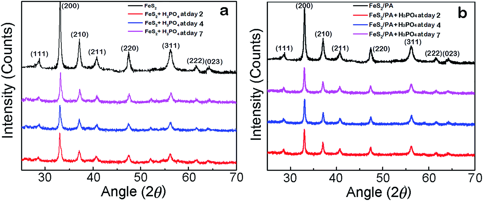
Three methods were employed to verify the long term stability of the device. First, a 10000 charge/discharge cycles at a fixed current density of 1 mA cm−2 was used to verify the long term capacitance retention property of the device (Fig. 4d) and cyclic voltammetry of FeS2/PA electrode at 300 mV s−1 scan rate to verify the long term cycling stability (Fig. 5a). We observed that after 10000 charge/discharge cycles, the charge storage in the device was at 97% of the maximum storage capability. Similar electrochemical stability was observed after conducting 10000 cycles of CV using the FeS2/PA electrode material. It should be noted from Fig. 5b that the current density was still at 40 mA cm−2, which is about 95% of the initial value; demonstrating the long term cyclic stability of the device prototype. Further we made a comparative CV analysis of fresh FeS2/PA electrode with FeS2/PA electrodes treated continuously with H3PO4 (pH 1.4, 2 M H3PO4 aqueous solution) for two, four and seven days respectively demonstrating similar current density and shape (Fig. 5c).
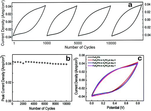 |
| | Fig. 5 Functional stability experiment. (a) CV cycles comparison for shape and storage capability retention from first to ten thousand cycle indicating that current density of 0.04 A cm−2 is maintained throughout. (b) Peak current density following 10000 cycles was maintained at 0.04 A cm−2 c−1. CV comparison of fresh FeS2/PA electrode with FeS2/PA electrodes treated with H3PO4 for two, four and seven days respectively demonstrating similar current density and shape. | |
3.5. Evaluating the structural stability of the electrode material used in the device
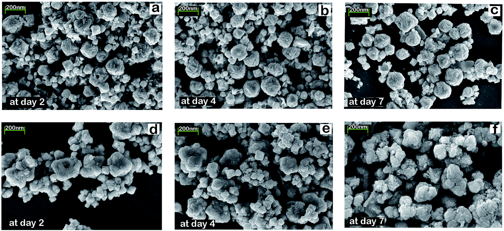
We conducted two experiments to establish the structural stability of FeS2/PA material in H3PO4 environment (pH 1.21–1.4). First, freshly prepared samples of FeS2 (100 mg each) was kept in 1.4 pH 5 ml 2 M H3PO4 for two, four, and seven days in three different vials. After completing the second, fourth and seventh day respectively; FeS2 was taken out from the vials, and conducted XRD and SEM investigation on those samples. Same experiment was conducted for the FeS2/PA material. The XRD graph in Fig. 6 exhibits the same peaks for all samples for each specific day for both FeS2 and FeS2/PA materials. We did not observe any difference in the XRD peaks and further we observed similar morphology in the SEM analysis as shown in Fig. 7; thus demonstrating the stability of the material even after seventh day in H3PO4 environment.
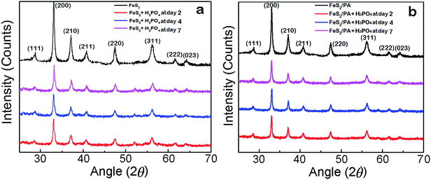 |
| | Fig. 6 Structural comparison (XRD). (a) XRD of FeS2 at second, fourth and seventh day of H3PO4 treatment. (b) XRD of FeS2/PA at second, fourth and seventh day of H3PO4 treatment. | |
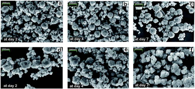 |
| | Fig. 7 SEM images of FeS2 and FeS2/PA nanoparticles after 2, 4 and 7 days of H3PO4 treatment (a) FeS2 at day 2. (b) FeS2 at day 4. (c) FeS2 at day 7. (d) FeS2/PA at day 2. (e) FeS2/PA at day 4. (f) FeS2/PA at day 7. | |
3.6. Testing the efficacy of the device
Initially the device had to be charged using a 2 V DC power source. For optimal efficiency of the device, the first charging should be done approximately for 1 hour. Then onward, subsequent charging need not require more than 5 minute. Once the device was fully charged, three devices are connected in a series circuit, which is sufficient to glow an light emitting diode (LED) device for more than 1 hour (ESI video file 1†) and could operate a simple electrical motor (ESI video file 2†). The minimum voltage requirement of the LED was 1.6 V and 20 μA current. The device had a charge storage capacity of approximately 20 mA h and the maximum discharging current is 30 mA (device dimension 2 cm2). If the size of the device was increased, then the discharge carrying capacity would subsequently increase, and it could run a DC motor, stepper motor etc. The device could be more extremely flexible and foldable by coating of graphite on a cello-tape.
3.7. Proposed model of charge transfer and the overall discussion
The key question is how the proposed device stored electrical energy? There could be multiple strategies by which charge could be stored viz., electrochemical double-layer capacitance, pseudo-capacitance, battery effects and other small capacitive effects.47,48 The charge accumulation at the electrode–electrolyte interface generates electrochemical double-layer capacitance and possibly some pseudo-capacitance was generated due to certain faradic reaction on the electrode surface6,8,49 (Fig. 8). Thus the total capacitance produced by the device was due to the addition of two capacitances along with the other small capacitive effects. Further the property of sulfur ions to work as electron sink and thus causing delocalized electronic states, might help in efficient electron transfer and optimal kinetics to run the device efficiently.15,26–28,41,44 Further, the entrapment of FeS2 nano particles in the conducting polymer matrix of PA possibly offers better electrochemical activity/conductivity.43 The device which had been developed here is in its crudest form. If this is refined further, this could find several applications in the emerging domain of sustainable energy storage devices for flexible electronics.
 |
| | Fig. 8 Proposed charge storage mechanism of the device. (a) Electrical double layer formation during charging. The electrolyte (H3PO4) dissociates and H+ ions migrate towards the cathode and H2PO4− ions migrate towards the anode. (b) Possible pseudo capacitive effects occur at the electrode surface. Since sulfur atom is a nucleophile having enough electron density, which will easily create an adduct with H+ and thus possibly forming H–S hydrogen bonding. Whereas Fe center has enough positive character, so it can act as an electrophile, where it can create a loose electrostatic bonds with oxo donor group of phospho ion. In summary these features of nano FeS2 offers it a bi-functional electrode character. | |
4. Conclusions
In this work, we propose an innovative and novel application of nano FeS2viz., as a symmetric charge storage device that is flexible, portable, light weight; along with its fabrication details. In its present laboratory prototype form; it powers solid-state electronic devices and electric motors. Further refinements of this device will open new avenues in the field of sustainable charge storage devices and low power electronics.
Acknowledgements
Acknowledgement This work is part of AD's doctoral thesis. AD is supported by MHRD, GOI. MR is supported by SB/FT/CS-199/2013 (DST- SERB, GOI).
References
- H. Chen, T. N. Cong, W. Yang, C. Tan, Y. Li and Y. Ding, Science Direct Prog, Nat. Sci., 2009, 19, 291 CAS.
- H. Ibrahim, A. Ilinca and J. Perron, Renewable Sustainable Energy Rev., 2008, 12, 1221 CrossRef CAS.
- Z. Song and H. Zhou, Energy Environ. Sci., 2013, 6, 2280 CAS.
- H. Kim, J. Lee, H. Ahn, O. Kim and M. J. Park, Nat. Commun., 2015, 6, 7278 CrossRef CAS PubMed.
- D. Zang, J. P. Tu, Y. J. Mai, J. Zang, Y. Q. Quio and X. L. Wang, J. Australas. Ceram. Soc., 2012, 2, 189 Search PubMed.
- Z. Li, Z. Zhou, G. Yun, K. Shi, X. Lv and B. Yang, Nanoscale Res. Lett., 2013, 8, 2 CrossRef PubMed.
- X. H. Lu, D. Z. Zheng, T. Zhai, Z. Q. Liu, Y. Y. Huang, S. L. Xie and Y. X. Tong, Energy Environ. Sci., 2011, 4, 2915 CAS.
- Q. Chen, X. Li, X. Zang, Y. Cao, Y. He, P. Li, K. Wang, J. Wei, D. Wud and H. Zhu, RSC Adv., 2014, 4, 36253 RSC.
- V. K. Thakur, G. Q. Ding, J. Ma, P. S. Lee and X. H. Lu, Adv. Mater., 2012, 24, 4071 CrossRef CAS PubMed.
- Y. Wang and W. H. Zhong, ChemElectroChem, 2015, 2, 22 CrossRef CAS.
- D. Larcher and J.-M. Tarascon, Nat. Chem., 2015, 7, 19 CrossRef CAS PubMed.
- I. Hadjipaschalis, A. Poullikkas and V. Efthimiou, Renewable Sustainable Energy Rev., 2009, 13, 1513 CrossRef.
- C. Schaber, P. Mazza and R. Hammerschlag, Electricity Journal, 2014, 05, 21 Search PubMed.
- A. Andrijanovits, H. Hoimoja and D. Vinnikov, Elektron. Elektrotech., 2012, 118, 21 Search PubMed.
- M. Lee, G. P. Kim, H. D. Song, S. Park and J. Yi, Nanotechnology, 2014, 25, 345601 CrossRef PubMed.
-
K. Bradbury, Energy storage technology review, Duke University, 2010, pp. 1–34, http://people.duke.edu/%7Ekjb17/tutorials/Energy_Storage_Technologies.pdf Search PubMed.
- A. Manthiram, A. V. Murugan, A. Sarkar and T. Muraliganth, Energy Environ. Sci., 2008, 1, 621 CAS.
- R. T. Lowson, Chem. Rev., 1982, 82, 461 CrossRef CAS.
- D. Rickard and G. W. Luther III, Chem. Rev., 2007, 2, 514 CrossRef PubMed.
- Y. N. Zhang, J. Hu, M. Law and R. Q. Wu, Phys. Rev. B: Condens. Matter Mater. Phys., 2012, 85, 085314 CrossRef.
- P. P. Altermatt, T. Kiesewetter, K. Ellmer and H. Tributsch, Sol. Energy Mater. Sol. Cells, 2002, 2, 71 Search PubMed.
- G. Srivastava, A. Das, T. S. Kusurkar, M. Roy, S. Airan, R. K. Sharma, S. K. Singh, S. Sarkar and M. Das, Mater. Express, 2014, 4, 23 CrossRef CAS.
- G. Srivastava, C. K. Das, A. Das, S. K. Singh, M. Roy, H. Kim, N. Sethy, A. Kumar, R. K. Sharma, S. K. Singh, D. Philip and M. Das, RSC Adv., 2014, 4, 58495 RSC.
- L. Zhu, B. J. Richardson and Q. Yu, Nanoscale, 2014, 6, 1029 RSC.
-
M. Das, G. Srivastava, C. Das, A. Dubey, N. Sethy, K. Bhargava, S. K. Singh and D. Philip, New AG International India, June 2015, pp. 41–42 Search PubMed.
-
H. Tributsch, Sulfur Its Significance for Chemistry, for the Geo- Bio- and Cosmosphere and Technology, ed. A. Müller and B. Krebs, Elsevier Science Publishers, 1984 Search PubMed.
- T. A. Bither, R. J. Bouchard, W. H. Cloud, P. C. Donohue and W. J. Siemons, Inorg. Chem., 1968, 7, 2208 CrossRef CAS.
- H. S. Jarret, W. H. Cloud, R. J. Bouchard, S. R. Butler, C. G. Frederick and J. L. Gillison, Phys. Rev. Lett., 1968, 21, 617 CrossRef.
- Y. Wang, H. Liao, J. Wang, X. Qian, Y. Zhu and S. Cheng, Int. J. Electrochem. Sci., 2013, 8, 4002 CAS.
- K. Lee, S. Cho, S. H. Park, A. J. Heeger, C.-W. Lee and S.-H. Lee, Nature, 2006, 441, 65–68 CrossRef CAS PubMed.
- H. Lin, L. Li, J. Ren, Z. Cai, L. Qiu, Z. Yang and H. Peng, Sci. Rep., 2013, 3, 1353 Search PubMed.
- M. Y. C. Teo, S. A. Kulinich, O. A. Plaksin and A. L. Zhu, J. Phys. Chem. A, 2010, 114, 4173 CrossRef CAS PubMed.
- Y. Bi, Y. Yuan, C. L. Exstrom, S. A. Darveau and J. Huang, Nano Lett., 2011, 11, 4953 CrossRef CAS PubMed.
- X. Qiu, M. Liu, T. Hayashi, M. Miyauchi and K. Hashimoto, Chem. Commun., 2013, 49, 1232 RSC.
- W. L. Liu, X. H. Rui, H. T. Tan, C. Xu, Q. Y. Yan and H. H. Hng, RSC Adv., 2014, 4, 48770 RSC.
- Y. K. Zhou, B. L. He, W. J. Zhou, J. Huang, X. H. Li, B. Wu and H. L. Li, Electrochim. Acta, 2004, 49, 257 CrossRef CAS.
- Y. Liao, C. Zhang, Y. Zhang, V. Strong, J. Tang, X. G. Li, K. K. Zadeh, E. M. V. Hoek, K. L. Wang and R. B. Kaner, Nano Lett., 2011, 11, 954 CrossRef CAS PubMed.
- M. Khalid, M. A. Tumelero and A. A. Pasa, RSC Adv., 2015, 5, 62033 RSC.
- C. Y. Wang, V. Mottaghitalab, C. O. Too, G. M. Spinks and G. G. Wallace, J. Power Sources, 2007, 163, 1105 CrossRef CAS.
- X. Rui, H. Tan and Q. Yan, Nanoscale, 2014, 6, 9889 RSC.
- Y. Zhu, L. Suo, T. Gao, X. Fan, F. Han and C. Wang, Electrochem. Commun., 2015, 54, 18 CrossRef CAS.
- R. Pauliukaite, C. M. Brett and A. P. Monkman, Electrochim. Acta, 2004, 50, 159 CAS.
-
C. Karunakaran, P. Santharaman and M. Das, Biosensors and Bioelectronics, Nanocomposite
Matrix Functionalization for Biosensors, ed. C. Karunakaran, R. Rajkumar and K. Bhargava, Elsevier, 2015, pp. 69–132 Search PubMed.
- A. Ennaoui, S. Fiechter, C. Pettenkofer, N. Alonso-Vante, K. Buker, M. Bronold, Ch. Hopfner and H. Tributch, Sol. Energy Mater. Sol. Cells, 1993, 29, 289 CrossRef CAS.
-
T. P. Dhakal, L. K. Ganta, D. Van Hart, C. R. Westgate, Annealing of FeS2 nano-crystal thin film, in Photovoltaic Specialists Conference (PVSC), 2012, 38th IEEE, pp. 000170–000173, DOI:10.1109/PVSC.2012.6317593.
- L. Viliciauskas, M. E. Tuckerman, G. Bester, S. J. Paddison and K. D. Kreuer, Nat. Chem., 2012, 4, 461 CrossRef PubMed.
- Z. Qin, Z. J. Li, M. Zhang, B. C. Yang and R. A. Outlaw, J. Power Sources, 2012, 217, 303 CrossRef CAS.
- J. Bae, M. K. Song, Y. J. Park, J. M. Kim, M. L. Liu and Z. L. Wang, Angew. Chem., Int. Ed., 2012, 51, 4934 CrossRef PubMed.
- J. T. Zhang, J. W. Jiang, H. L. Li and X. S. Zhao, Energy Environ. Sci., 2011, 4, 4009 CAS.
Footnotes |
| † Electronic supplementary information (ESI) available. See DOI: 10.1039/c6ra01973k |
| ‡ SS and MD are co-corresponding authors. |
|
| This journal is © The Royal Society of Chemistry 2016 |
Click here to see how this site uses Cookies. View our privacy policy here. 
 Open Access Article
 This Open Access Article is licensed under a Creative Commons Attribution-Non Commercial 3.0 Unported Licence