
Solution synthesis of pure 2H CuFeO2 at low temperatures†
Yi Jin and
George Chumanov*
Department of Chemistry, Center for Optical Materials Science and Engineering Technologies (COMSET), Clemson University, Clemson, South Carolina 29634, USA. E-mail: gchumak@clemson.edu
First published on 4th March 2016
Abstract
Pure 2H CuFeO2 nanoplates with a thickness of about 100 nm were synthesized at temperatures as low as 100 °C from CuI and FeCl3·6H2O. Systematic studies revealed that the formation of 2H CuFeO2 was affected by reactant concentrations, basicity, temperature and the reaction time. The material was characterized by powder X-ray diffraction, electron microscopy, Raman and absorption spectroscopy. 2H CuFeO2 has a band gap of 1.33 eV, high absorption coefficient of 3.8 × 104 cm−1 at 700 nm and is highly photostable. When incorporated into an indium tin oxide/ZnO/2H CuFeO2/graphite/carbon black structure an open circuit photovoltage of 0.29 V was observed. The material appears promising for solar applications.
Introduction
Solution processing thin film solar cells is a promising approach for broad utilization of solar energy. Successful thin film solar cells should balance power conversion efficiency (PCE), manufacturing cost, stability and environmental friendliness. The absorbing layer in efficient thin film mono-junction solar cells should satisfy several requirements. (a) The band gap of the material should be close to 0.9–1.6 eV, the optimum for a mono-junction cell operating at AM 1.5G.1 (b) The absorption coefficient should be larger than 104 cm−1 to provide at least 80% of light absorption within a film thickness of about 1 μm. The thickness of the absorption layer in most thin film solar cells, such as CuInxGa(1−x)Se2, Cu2ZnSnS4(Se), organic solar cells, and perovskite solar cells, are less than 2 μm.2 Higher absorption coefficients permit smaller absorption depths thereby favoring the carrier extraction relative to the carrier recombination. (c) The carrier diffusion distance should be longer than the absorption depth. (d) The exciton binding energy should be low to produce free carriers rather than bound states. The excition binding energy in inorganic materials is often lower due to the higher dielectric constant that effectively screens the electrostatic attraction between the carriers. (e) In structures where the absorbing layer is an intrinsic semiconductor sandwiched between p- and n-type semiconductor layers, the p–i–n solar cell, the valance band maximum of the absorber should be slightly below and the conduction band minimum slightly above the corresponding bands of p- and n-layers, respectively. (f) The light absorbing material should be cheap, stable, easily processed, and environmentally friendly. A solution processed CuFeO2 could be an effective light absorption material since it meets most of the requirements mentioned above, including a suitable band gap, high absorption coefficient, low cost, high stability and environmental friendliness.CuFeO2 crystallizes in a rhombohedral (3R)-type3 structure with lattice parameters a = b = 3.034 Å, c = 17.163 Å, α = β = 90°, γ = 120° and a hexagonal (2H)-type4 structure with lattice parameters a = b = 3.035 Å, c = 11.449 Å, α = β = 90°, γ = 120°. 3R CuFeO2 is a p-type semiconductor with 1.47 eV (ref. 5) band gap and its conductivity is due to ionized Cu vacancies and interstitial oxygen.6 It has high light absorption coefficient of 7.5 × 104 cm−1 near the band gap edge at 700 nm (ref. 5) and sufficiently high hole mobility of 34 cm2 V−1 s−1 even at doping levels as high as 1.8 × 1019 cm−3.7 The high absorption coefficient and high mobility benefit the carrier generation and extraction. CuFeO2 is made of earth abundant elements and has good stability in aqueous environments,8 and as such was investigated as photocathodes for photoelectrochemical reduction of CO2,9,10 solar water reduction,5,11 and as a cathode material in Li batteries.12 Whereas 3R phase was somewhat characterized, only X-ray diffraction4 and theoretical calculation13 of eg and t2g occupancies of the Fe3+ are available for 2H CuFeO2.
CuFeO2 is often synthesized by solid state reactions at temperature higher than 850 °C under oxygen free atmosphere for more than 24 h resulting in 3R phase.9,12 Sol gel methods decreased the required reaction temperature and time to about 700 °C and 12 h, respectively.5,11 The electrodeposition of CuFeO2 precursor decreased the calcination temperature to 650 °C and the reaction time to 3 h.10 Hydrothermal synthesis further decreased the reaction temperature to below 200 °C but the resulting material was a mixture of 3R and 2H phases in a highly aggregated state of individual crystals hindering the formation of high quality thin films.14–16 Pure 2H CuFeO2 and other 2H delafossite-type oxides are difficult to synthesize.17 To the best of our knowledge, the only pure 2H CuFeO2 crystals were isolated from a mixture as a byproduct of the synthesis of iron–copper-arsenates.4
Here, we present a simple and reliable method to synthesize pure 2H CuFeO2 nanocrystals at 100 °C. We systematically studied the effect of the concentration of reactants, reaction temperature and reaction time on the formation and purity of 2H CuFeO2 and characterized the material using powder X-ray diffraction (PXRD), electron microscopy and spectroscopic techniques. The work was motivated by the need to study fundamental properties of this material and its potential suitability for solar applications. In preliminary studies reported here, we demonstrated that 2H CuFeO2 can be used as an efficient light absorbing material, capable of exhibiting the photovoltaic effect.
Experimental section
Materials
Fluorine doped tin oxide (FTO) glass (∼7 Ω sq−1) and indium tin oxide (ITO) glass (8–12 Ω sq−1) were received from Sigma and Delta Technologies, LTD, respectively. Polyethylene glycol 6000 (PEG 6000) (EMD Millipore), sodium hydroxide (BDH, ACS grade), potassium hydroxide (Ameresco, reagent grade), copper iodide (Acros Organics, 98%), iron(III) chloride hexahydrate (Macron, AR) and acetylene carbon black (50% compressed) (Stream Chemicals) were used as received. Zinc oxide nanoparticles and graphite suspension in 4-methyl-2-pentanone were synthesized following previously reported methods.18,19Instrumentation
UV-Vis-Near infrared extinction spectra and diffuse reflectance spectra were measured using a Shimadzu UV-3600 spectrophotometer. Powder X-ray diffraction data was collected using a Rigaku Ultima IV X-ray diffractometer with Cu Kα radiation (λ = 1.5418 Å) at 25 °C. Diffraction peaks were assigned by referring PDF card using card number 01-79-1546 for 2H-CuFeO2, 00-39-0246 for 3R-CuFeO2, 00-001-1053 for α-Fe2O3, 00-005-0667 for Cu2O and 00-040-0129 for Fe(OH,I)2.55. Crystallite sizes and phase ratios were calculated from PXRD using Scherrer equation and Rietveld quantitative analysis, respectively and Rigaku PDXL 1.8.1.0 software. Thickness measurements were performed using an AIST-NT SmartSPM-1000 atomic force microscope (AFM) operating in AC mode. Electron microscope images were obtained with Hitachi S-4800 field emission scanning electron microscopes. Raman spectra were collected using 514.5 nm light from an Ar+ ion laser (Innova 200, Coherent, 500 mW). Scattered light was collected by a f/1.2 camera lens in a backscattering geometry and analyzed by a triple spectrometer (Triplemate 1877, Spex) equipped with a CCD detector (iDUS 420, Andor). Raman spectra of indine and a mixture of chloroform and bromoform were used for spectral calibration. Laurell WS-400B-6NPP-Lite Manual Spinner was used for spin-coating. The current–voltage curves of solar cells were measured by using an electrochemical workstation (CH Instruments, CHI440) with linear sweep voltammetry. The solar cells were illuminated by an in-house built solar simulator equipped with a Mega-9 AM 1.5G filter at a calibrated intensity of 100 mW cm−2. The effective area of the solar cell was defined as 0.35 cm2 with a non-reflective metal mask.CuFeO2 synthesis
In a typical process, H2O (18 MΩ) (3.5 mL) was bubbled with high purity N2 over 30 min, in which a certain amount of CuI and FeCl3·6H2O was dispersed by stirring under N2 atmosphere over 15 min. NaOH or KOH solid was further dispersed in the mixture by strong stirring for 15 min following by dissolving additives with strong stirring for an additional 15 min. The reaction mixture was then heated in an oven at a set temperature between at 80 °C and 190 °C for a set time.Photovoltaic device fabrication
Devices were fabricated under an ambient environment. Glass/ITO/ZnO substrates prepared by following previously reported methods18,19 were coated with CuFeO2 particles by drop-casting from H2O suspension. The graphite layer, direct electrical contact to the ITO substrate, acetylene carbon black layer, and the top electrode were fabricated by following previous reported methods.18,19 The entire structure was mechanically clamped together with two binder clips.Results and discussion
Highly aggregated CuFeO2 crystals were previously synthesized by using water soluble Cu(II), Fe(III) salts and propionaldehyde as a reductant.20 When attempting to repeat this method, a sticky yellow polymer was formed as a byproduct due to the aldol reaction of propionaldehyde under high basic condition. The contamination by this insoluble polymer as well as the high aggregation state of the CuFeO2 crystals deemed this product unsuitable for application in thin film electronic devices. In addition, the final product was a mixture of 3R and unknown amorphous green compound(s) that did not produce PXRD peaks. In another reported method, Cu(II) and Fe(II) salts were used and, upon increasing pH of the reaction by the addition of NaOH, the newly formed Fe(OH)2 reduced Cu(II) to Cu(I) while simultaneously being converted to Fe(III).15 This reaction requires the exact stoichiometric ratio of Cu(II) and Fe(II) because an excess of Cu(II) will result in highly doped CuFeO2 with decreased carrier mobility6 and an excess of Fe(II) will result in α-Fe2O3 byproduct that is difficult to remove. Pure Fe(II) salts without Fe(III) are also difficult to obtain. In addition, the method produced a mixture of 3R and 2H phases.The method for synthesizing the pure 2H phase of CuFeO2 described here is based on using Cu(I) and Fe(III) as a more stable iron salt as compared to Fe(II). NaI, which was formed when CuI reacted with FeCl3·6H2O and NaOH, reduced Cu(II) that could be present in the reaction to Cu(I). The addition of an excess amount of CuI can produce Cu2O as a byproduct; however it can be easily removed by washing with ammonium hydroxide. This method enabled the synthesis of pure 2H CuFeO2 phase.
The effect of the reaction time and temperature on the formation of CuFeO2 was studied at 80 °C, 90 °C, 120 °C, 150 °C and 190 °C in the reaction mixture comprised of 0.75 mmol CuI, 0.75 mmol FeCl3·6H2O, 5.5 mmol NaOH and 3.5 mL H2O (Table S1†). As can be seen from PXRD spectra (Fig. S1†), a mixture of 3R and 2H phases was always formed even after the reaction time of 48 h at 150 °C. The ratio of the two phases also remained roughly the same independent of the reaction temperature and time. When the reaction was carried at 80 °C for 24 h, α-Fe2O3, Fe(OH,I)x, and Cu2O were also detected as products in addition to 3R and 2H CuFeO2.
The effect of the reaction basicity was studied at 190 °C (Table S2†). PXRD indicated that only α-Fe2O3 and Cu2O were formed when using stoichiometric amount NaOH (3.00 mmol) (Fig. S2†). A small increase of NaOH amount to 3.35 mmol resulted in pure, primarily 3R CuFeO2 with a small contribution from 2H CuFeO2 (Fig. S2†). The addition of 13.5 mmol NaOH substantially increased the amount of 2H CuFeO2 in the mixture. In an attempt to further shift the formation equilibrium towards 2H phase, additives such as polyethylene glycol (PEG) 6000, propanoic acid and 5-phenylpentanoic acid were considered (Table S3†). However, as can be seen from PXRD spectra (Fig. S3†), these additives did not change the phase composition of CuFeO2.
It was assumed based on the initial experiments that the reaction at high basic conditions could yield pure 2H CuFeO2 phase. Indeed, as the amount of NaOH was increased the purity of 2H CuFeO2 phase also increased until the pure 2H phase, as was determined from PXRD, was obtained at 55.5 mmol NaOH, at 120 °C for 24 h (Fig. 1 and Table S4†). The reaction intermediates were captured by changing the reaction time (Table S5†). A mixture of a brown suspension, most likely amorphous Fe(OH)3·xH2O that cannot be detected by PXRD, and a blackish orange precipitate composed of 2H CuFeO2 and Cu2O mixture was obtained after 1.5 h reaction (Fig. S4†). Slightly longer reaction time, 2 h, resulted in pure 2H CuFeO2 phase. Contrary to the expectation, further increasing of the reaction time to 48 h under the same conditions did not result in a significantly larger crystallite size from 42 nm initially observed after 6 h. However, increasing the reaction temperature had a profound effect on the crystallite size as was evident from PXRD (Fig. 2). The crystallite size grew from 42 nm at 100 °C to 58 nm at 160 °C and to 73 nm at 200 °C (Table S6†). Relative diffraction intensities of PXRD did not changed when the amount of reactants (CuI and FeCl3·6H2O) decreased from 0.75 to 0.25 mmol. Further decreasing the amount to 0.07 mmol resulted in Cu2O presence in the product as well as poor reproducibility of the reaction indicating that the formation of 2H CuFeO2 is a concentration dependant process (Table S6 and Fig. S5†). When KOH was used as base in the reaction, pure 2H CuFeO2 was only formed at relative high concentrations of CuI and FeCl3·6H2O; decreasing the concentration resulted in the inclusion of a small percent of 3R CuFeO2, the amount of which did not change when the reaction time was increased from 18 h to 48 h (Table S7, Fig. S6 and S7†). It was also observed that 2H CuFeO2 synthesized from KOH had better dispersibility in H2O leading to more uniform films when drop casting compared to that synthesized from NaOH.
| 2FeCl3 + 2CuI → I2 + 2FeCl2 + 2CuCl | (1) |
| I2 + 2FeCl2 + 2CuCl + 8NaOH + xH2O → 2Fe(OH)3·xH2O + 2CuOH + 6NaCl + 2NaI | (2) |
| 2CuOH → Cu2O + H2O | (3) |
| Cu2O + 2NaOH + H2O ⇄ 2Na[Cu(OH)2] | (4) |
| Fe(OH)3·xH2O + Na[Cu(OH)2] → CuFeO2 + NaOH + (2 + x)H2O | (5) |
 | ||
| Fig. 1 PXRD spectra of CuFeO2 synthesized by using CuI (0.75 mmol), FeCl3·6H2O (0.75 mmol), H2O (3.5 mL) at 120 °C for 24 h with various amount of NaOH. | ||
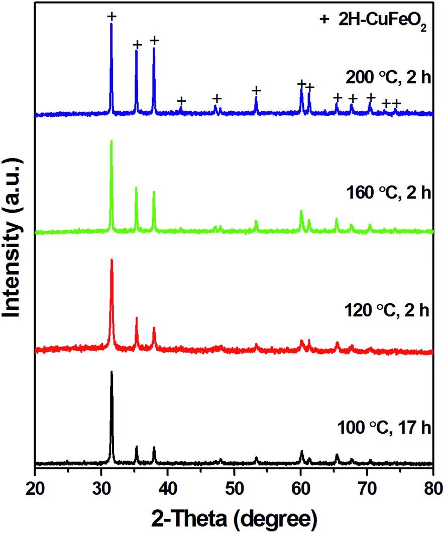 | ||
| Fig. 2 PXRD spectra of CuFeO2 synthesized by using CuI (0.75 mmol), FeCl3·6H2O (0.75 mmol), H2O (3.5 mL), NaOH (55.5 mmol) at various reaction temperatures. | ||
The proposed mechanism for the formation of CuFeO2 at high basic condition is based on the reactions (1)–(5). Fe3+ is reduced to Fe2+ by CuI at low pH (eqn (1)) and then reverted back as Fe(OH)3·xH2O because I2 is an efficient oxidant for Fe2+ at high basic condition (eqn (2)).21 At the same basic condition, CuOH is formed (eqn (2)) that is not stable at room temperature and is dehydrated to Cu2O (eqn (3)). The formation of Cu2O was confirmed by its orange color and PXRD (Fig. S4†). The complexation of Cu2O with OH− at high basic condition produces [Cu(OH)2]− (eqn (4)) thus increasing the solubility of Cu2O that is further increased with the increasing of the reaction temperature.22 [Cu(OH)2]− reacts with amorphous Fe(OH)3·xH2O and crystallizes into CuFeO2 (eqn (5)).
The reaction between the dissolved [Cu(OH)2]− and insoluble Fe(OH)3·xH2O is limited by the diffusion of the iron species. Amorphous Fe(OH)3·xH2O is highly hydrated and forms a gel-like matrix that is more stable against precipitation when high concentrations are used. At low concentrations, the hydrated network is not as developed resulting in faster precipitation. The formation of the gel-like matrix requires vigorous stirring during the addition of NaOH in order to provide sufficient mixing for the homogeneous reaction. Good mixing and high concentrations favor the reaction of [Cu(OH)2]− and Fe(OH)3·xH2O into CuFeO2, whereas low concentrations and insufficient mixing results in the fast precipitation of Fe(OH)3·xH2O. When heated, the precipitated Fe(OH)3·xH2O undergoes dehydration resulting in α-Fe2O3 with reduced reactivity towards [Cu(OH)2]− due to low solubility of α-Fe2O3.23,24 The formation of CuFeO2 from [Cu(OH)2]− and Fe(OH)3·xH2O and the formation of α-Fe2O3 by the dehydration of Fe(OH)3·xH2O are two competing paths. When α-Fe2O3 is formed, it remains as a byproduct without being converted into CuFeO2 even after heat treatment for 7 days at 220 °C.
Scanning electron microscopy revealed that 2H CuFeO2 crystallized into irregular plates at 100 °C but more hexagonal plates were formed at 200 °C when using NaOH (Fig. 3 and S8†). The thickness of the plates was determined from the SEM images to be about 100 nm and did not significantly change with increasing the reaction temperature from 160 to 200 °C. SEM images, combining with PXRD, indicated that the crystallinity was improved at high temperature. Although PXRD showed a small amount of 3R CuFeO2, predominantly 2H CuFeO2 was synthesized with low concentrations of reactants in KOH, no significant difference was noticeable in SEM images when compared to pure 2H CuFeO2 synthesized with high concentrations of the reactants. 2H CuFeO2 synthesized from KOH was crystallized into irregular disk with the thickness about 90 nm (Fig. S9 and S10†).
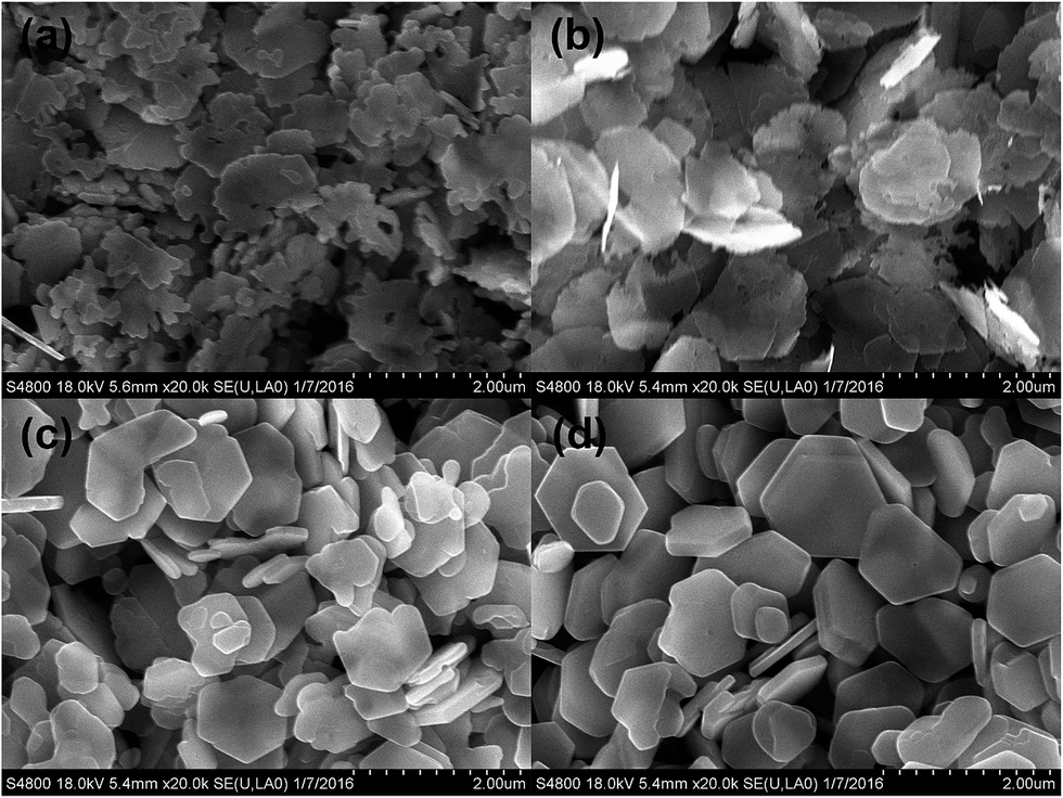 | ||
| Fig. 3 SEM images of 2H CuFeO2 synthesized by using CuI (0.75 mmol), FeCl3·6H2O (0.75 mmol), H2O (3.5 mL), NaOH (55.5 mmol) at (a) 100 °C, (b) 120 °C, (c) 160 °C and (d) 200 °C, respectively. | ||
Raman spectra were collected to monitor the formation of CuFeO2 at different basicities and reaction temperatures (Fig. 4). Whereas the Raman spectrum of 3R CuFeO2 phase was previously described, to the best of our knowledge this is the first report of Raman spectra of 2H CuFeO2. The 2H phase exhibits three distinguishable bands: a doublet at 351, 365 cm−1 and a single band at 690 cm−1. As the reaction temperature was increased from 120 °C to 200 °C the doublet became more pronounced, most likely due to the improved crystallinity. For a mixture of 2H and 3R phases synthesized at 24 mmol of NaOH that showed similar intensities of the corresponding diffraction peaks in PXRD spectra (Fig. 1) only a broad band at 346 cm−1 was observed in Raman spectra. The decrease of NaOH to 6.5 mmol resulted in the predominant 3R phase based on PXRD and two characteristic bands in Raman spectra at 348 and 688 cm−1 previously assigned in the literature.25 The Raman spectra of both 2H and 3R phases did not change after exposing the samples to high intensity (∼100 W cm−2) of laser light (514.5 nm) under ambient conditions for 2 h thereby indicating that both 3R and 2H phases of CuFeO2 are expected to have good photostability.
 | ||
| Fig. 4 Raman spectra of CuFeO2 synthesized with NaOH as base. (a) NaOH 6.5 mmol, 120 °C. (b) NaOH 24.0 mmol, 120 °C. (c) NaOH 55.5 mmol, 120 °C. (d) NaOH 55.5 mmol, 200 °C. | ||
2H CuFeO2 thin films can be easily fabricated by drop-casting aqueous suspensions on various substrates. As can be seen in Fig S11,† a glass/ITO/ZnO substrate was fully covered by CuFeO2 plates. The band-edge absorption for 2H CuFeO2 film was determined to be at 935 nm corresponding to 1.33 eV band gap (Fig. 5). The absorption coefficient near the band gap edge at 700 nm was calculated to be 3.8 × 104 cm−1. In order to compare optical properties of 3R and 2H CuFeO2, diffuse reflectance spectra of the corresponding powders were measured against BaSO4 standard. The diffuse reflectance spectra were quite similar for both compounds, as can be seen in Fig. 6.
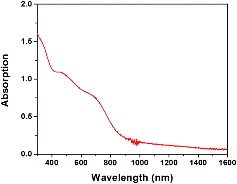 | ||
| Fig. 5 UV-Vis-Near infrared absorption spectrum of 2H CuFeO2 film drop-casted on a glass substrate. The average thickness of the film was 450 nm. | ||
 | ||
| Fig. 6 Diffuse reflectance spectra of 2H and 3R CuFeO2 powder on BaSO4 standard white board. As calculated from PXRD by using Rietveld quantitative analysis, 3R CuFeO2 powder contained 6.1 ± 0.5% 2H CuFeO2 phase. | ||
In order to establish the potential applicability of 2H CuFeO2 for photovoltaic applications, a simple thin film device was fabricated by the sequential deposition of ZnO, 2H CuFeO2, graphite and carbon black layers on ITO substrates, as described in Experimental section. The device exhibited 0.29 V open circuit potential, 8.8 μA cm−2 short circuit currents, 0.17 fill factor and 0.0005% power conversion efficiency (Fig. 7). The low fill factor is indicative of a low shunt and high series resistance of the structure. High series resistance was most likely at ZnO/CuFeO2 or/and CuFeO2/graphite interfaces leading to an inefficient carrier extraction. The other two interfaces, specifically ITO/ZnO and graphite/carbon black can be ruled out because the same interfaces were used previously in high efficient perovskite cells.19 Even though the described simple structure showed only the low power conversion efficiency, the fact that 2H CuFeO2 exhibited photovoltaic effect, has a high light absorption coefficient and suitable band gap as well as good photostability warrants its further studies for solar applications.
 | ||
| Fig. 7 J–V curves of a typical ITO/ZnO/CuFeO2/graphite/carbon black structure under AM 1.5G illumination. | ||
Conclusion
CuFeO2 was synthesized at temperature as low as 90 °C from CuI and FeCl3·6H2O. At low basic conditions, a mixture of 3R and 2H phases of CuFeO2 was formed. At high basic conditions, pure 2H CuFeO2 was formed as nanoplates with a thickness of about 100 nm. The crystallinity of 2H CuFeO2 phase increased with the increase of reaction temperature. The material has 1.33 eV band gap and high absorption coefficient of 3.8 × 104 cm−1 near the band gap edge at 700 nm. It demonstrated a photovoltaic effect when placed into thin film structures composed of ITO/ZnO/2H CuFeO2/graphite/carbon black. To the best of our knowledge, this is the first example of solution synthesis of pure 2H CuFeO2 at low temperature. The synthesized material has potential for applications in solar cells and for solar catalysis.Acknowledgements
We gratefully acknowledge the support of this work through Department of Energy, Grant DE-FG02-06ER46342, and Clemson University Center for Optical Materials Science and Engineering Technologies.References
- P. Baruch, A. De Vos, P. T. Landsberg and J. E. Parrott, Sol. Energy Mater. Sol. Cells, 1995, 36, 201–222 CrossRef CAS.
- M. A. Green, K. Emery, Y. Hishikawa, W. Warta and E. D. Dunlop, Prog. Photovolt: Res. Appl., 2016, 24, 3–11 CrossRef.
- T. Elkhouni, M. Amami, C. V. Colin and A. Ben Salah, Mater. Res. Bull., 2014, 53, 151–157 CrossRef CAS.
- H. Effenberger, Acta Crystallogr., Sect. C: Cryst. Struct. Commun., 1991, 47, 2644–2646 CrossRef.
- M. S. Prevot, N. Guijarro and K. Sivula, ChemSusChem, 2015, 8, 1359–1367 CrossRef CAS PubMed.
- M. A. Marquardt, N. A. Ashmore and D. P. Cann, Thin Solid Films, 2005, 496, 146–156 CrossRef.
- P. Dordor, J. P. Chaminade, A. Wichainchai, E. Marquestaut, J. P. Doumerc, M. Pouchard, P. Hagenmuller and A. Ammar, J. Solid State Chem., 1988, 75, 105–112 CrossRef CAS.
- S. Omeiri, B. Bellal, A. Bouguelia, Y. Bessekhouad and M. Trari, J. Solid State Electrochem., 2009, 13, 1395–1401 CrossRef CAS.
- J. Gu, A. Wuttig, J. W. Krizan, Y. Hu, Z. M. Detweiler, R. J. Cava and A. B. Bocarsly, J. Phys. Chem. C, 2013, 117, 12415–12422 CAS.
- U. Kang, S. K. Choi, D. J. Ham, S. M. Ji, W. Choi, D. S. Han, A. Abdel-Wahab and H. Park, Energy Environ. Sci., 2015, 8, 2638–2643 CAS.
- M. S. Prevot, Y. Li, N. Guijarro and K. Sivula, J. Mater. Chem. A, 2016, 4, 3018–3026 CAS.
- A. M. Sukeshini, H. Kobayashi, M. Tabuchi and H. Kageyama, Solid State Ionics, 2000, 128, 33–41 CrossRef CAS.
- K. Toyoda, R. Hinogami, N. Miyata and M. Aizawa, J. Phys. Chem. C, 2015, 119, 6495–6501 CAS.
- W. C. Sheets, E. Mugnier, A. Barnabe, T. J. Marks and K. R. Poeppelmeier, Chem. Mater., 2006, 18, 7–20 CrossRef CAS.
- M. John, S. Heuss-Aßbichler and A. Ullrich, J. Solid State Chem., 2016, 234, 55–62 CrossRef CAS.
- D. Xiong, Y. Qi, X. Li, X. Liu, H. Tao, W. Chen and X. Zhao, RSC Adv., 2015, 5, 49280–49286 RSC.
- T. I. Draskovic, M. Yu and Y. Wu, Inorg. Chem., 2015, 54, 5519–5526 CrossRef CAS PubMed.
- Y. Jin and G. Chumanov, Chem. Lett., 2014, 43, 1722–1724 CrossRef.
- Y. Jin and G. Chumanov, ACS Appl. Mater. Interfaces, 2015, 7, 12015–12021 CAS.
- X. Qiu, M. Liu, K. Sunada, M. Miyauchi and K. Hashimoto, Chem. Commun., 2012, 48, 7365–7367 RSC.
- J. Wei, Y. Xu, Z. Han and Q. Yue, Wujiyan Gongye, 2007, 39, 47–49 CAS.
- D. Palmer, J. Solution Chem., 2011, 40, 1067–1093 CrossRef CAS.
- I. I. Diakonov, J. Schott, F. Martin, J. C. Harrichourry and J. Escalier, Geochim. Cosmochim. Acta, 1999, 63, 2247–2261 CrossRef CAS.
- J.-H. Jang, B. A. Dempsey and W. D. Burgos, Environ. Sci. Technol., 2007, 41, 7303–7308 CrossRef CAS PubMed.
- S. P. Pavunny, A. Kumar and R. S. Katiyar, J. Appl. Phys., 2010, 107, 013522 CrossRef.
Footnote |
| † Electronic supplementary information (ESI) available: Additional data including detailed experimental conditions, additional PXRD spectra, SEM images and diffuse reflectance spectra. See DOI: 10.1039/c6ra01901c |
| This journal is © The Royal Society of Chemistry 2016 |