Fabrication and characterization of flexible films of poly(vinylidene fluoride)/Pb(Fe0.5Ti0.5)O3−δ multi-ferroic nano-composite†
Snehlata Aggarwala,
Sreeja K. S.b,
S. Chakrabartia,
V. R. Palkara and
Arup R. Bhattacharyya*b
aCentre for Excellence in Nanoelectronics, Department of Electrical Engineering, Indian Institute of Technology Bombay, Powai, Mumbai-400076, India
bDepartment of Metallurgical Engineering and Materials Science, Indian Institute of Technology Bombay, Powai, Mumbai-400076, India. E-mail: arupranjan@iitb.ac.in; Fax: +91-22-2572 6975; Tel: +91-22-2576-7634
First published on 18th April 2016
Abstract
Pb(Fe0.5Ti0.5)O3−δ (PTFO) is one of the few multiferroic materials that exhibits coupled co-existence of ferroelectricity and ferromagnetism at room temperature. In this study, phase-pure PTFO multiferroic nanoparticles were dispersed in poly(vinylidene fluoride) (PVDF) matrix via melt-mixing followed by compression molding in order to make flexible film of PVDF/PTFO nanocomposite. Phase pure PTFO nanoparticles with an average particle size of ∼32 nm were synthesized by co-precipitation method. PVDF/PTFO flexible films were prepared, wherein PTFO nanoparticles were varied from 5–25 wt%. The magnetic, ferroelectric, dielectric, magneto-dielectric coupling and morphology, as well as structural properties of these films were systematically investigated. The well saturated magnetic hysteresis loops could confirm the ferromagnetic properties associated with PVDF/PTFO nanocomposite films. The variation of dielectric permittivity and dielectric loss was investigated at frequencies ranging from 10 Hz to 10 MHz for these nanocomposites. The maximum polarization, saturation magnetization and dielectric permittivity were increased with increasing concentration of the PTFO nanoparticles. The ferroelectric, magnetic and magneto-capacitive behaviour at room temperature could suggest the multiferroic nature of the nanocomposite films with significant magnetodielectric coupling.
Introduction
Magnetoelectric–multiferroic single-phase materials are characterized by the coupled co-existence of ferroic orders, typically ferromagnetism and ferroelectricity. Attempts to identify single-phase systems exhibiting both ferromagnetic and ferroelectric orders were reported by Landau and Lifshitz by analyzing the presence of magnetoelectric coupling on the basis of crystal symmetry.1 The magnetoelectric coupling allows a control of magnetization by electric field,2 and polarization by applying magnetic field.3 In particular, magnetoelectric–multiferroic materials offer potential applications in information storage,4 spintronics and sensors. Unfortunately, few materials are known to be magnetoelectric–multiferroic at room temperature. Bismuth ferrite (BiFeO3) is one of the few room-temperature magnetoelectric–multiferroics; however, it suffers from the issues of high electrical conductivity, non-stoichiometric behaviour,5 and high dielectric loss, which limit its use for practical application.6,7A different perspective from the influence of the single-phase magnetoelectric materials, the larger design flexibility of multiferroic composites permits the introduction of multifunctional properties, in which the coupling interaction between the piezoelectric and magnetostrictive components gives rise to a magnetoelectric (ME) response which is several orders of magnitude higher than those in single-phase ME materials.8 Several ceramic composites prepared from the combination of ferroelectric materials viz.; PbZrxTi1−xO3, 0.7PbMg1/3Nb2/3O3–0.3PbTiO3, BaTiO3 and ferromagnetic materials viz.; Tb1−xDyxFe2, NiFe2O4, CoFe2O4, La1−xSrxMnO3 show notable magnetoelectric properties.9–15 However, the ceramic composites pose serious problems like inter-diffusion, chemical reaction, differential thermal expansion during high temperature processing (>720 °C) and may also become fragile, which hinder their application potential. These problems can be alleviated in polymer based composites, which can be easily fabricated by conventional low temperature processing (<270 °C) into a variety of forms, such as thin sheets or moulded shapes, and can exhibit improved mechanical properties.16 Numerous other problems, such as high leakage current and dielectric losses, which lead to failure during operation17,18 can be eliminated in such polymer based composites. Significant improvement in the ME response has been observed in polymer based nanocomposite films.16
Reddy et al. have prepared hot-pressed poly(vinylidene fluoride) (PVDF)/BiFeO3 composite films and magnetic polarization of the composite films was enhanced as compared to pure BiFeO3.19 Bhadra et al. reported the synthesis of PVDF/BiFeO3 nanocomposite and observed an enhanced electrical conductivity and low-loss (∼0.18) dielectric permittivity.20 A study on poly(methyl methacrylate)/BiFeO3 nanocomposite films with 2.5 to 10 vol% of BiFeO3 showed that the nanocomposite films exhibited very low electrical conductivity (in the order of 10−12 ohm−1 cm−1) and low dielectric loss (tan![[thin space (1/6-em)]](https://www.rsc.org/images/entities/char_2009.gif) δ ∼ 0.04) characteristics as compared to bulk BiFeO3.21 In another report on poly(vinyl acetate) (PVAc)/BiFeO3 nanocomposites, the nanocomposites prepared by surface modified BiFeO3 comprise favorable magneto-dielectric properties.22 Poly(vinyl alcohol) (PVA)/BiFeO3 nano-composite films also showed multiferroic properties.23
δ ∼ 0.04) characteristics as compared to bulk BiFeO3.21 In another report on poly(vinyl acetate) (PVAc)/BiFeO3 nanocomposites, the nanocomposites prepared by surface modified BiFeO3 comprise favorable magneto-dielectric properties.22 Poly(vinyl alcohol) (PVA)/BiFeO3 nano-composite films also showed multiferroic properties.23
Previously, our group has reported the single-phase multiferroic properties of bulk PbTi0.5Fe0.5O3 (PTFO), with the coupled coexistence of ferromagnetic and ferroelectric ordering at room temperature.24 Despite being technologically promising in terms of applications, so far only few studies on PTFO have been reported.25,26 Multiferroic materials as nanoparticles have been well known to exhibit properties very different than those exhibited by their bulk counterparts. We have prepared phase-pure PTFO nanoparticles and could observe the multiferroic properties, where in ferroelectric and ferromagnetic properties coexist at room temperature.27 Presence of both magnetic and ferroelectric properties at nanoscale, even at room temperature is remarkable from technology point of view, and flexible films with such a material, if fabricated, might also be strikingly important for a variety of applications due to their flexibility and ease of processing in casting as thin films on larger areas and on non-planer structures. PVDF is a semi-crystalline polymer exhibiting ferroelectric, pyroelectric and piezoelectric properties.28 It exhibits four crystal polymorphs, viz.; α, β, γ and δ, among which α and β phases being the most common polymorphs; they represent the non-polar and polar phases, respectively.29,30 PVDF was chosen as the polymer matrix as it has already been well studied and commercialized for various applications such as in transducers as well as in pyroelectric and piezoelectric devices. PVDF exhibits good mechanical properties, chemical resistance, electrical resistivity and processability. Furthermore, it exhibits high permittivity and a dissipation factor relatively low than those of other polymers,31 making it a potential candidate for several technological applications.32
In this study, we report the structure, morphology, magnetic, ferroelectric, dielectric and magneto-capacitive properties of flexible films of novel two-phase polymer nanocomposites comprising of PVDF and nanocrystalline (∼32 nm), multiferroic PTFO nanoparticles. It is to be noted that the utilization of PTFO nanoparticles in any type of polymer matrix (PVDF) is reported for the first time by us. It is also to be noted that PTFO nano-particles have never been used before for such multiferroic nanocomposites. Multiferroic PTFO nanoparticles were introduced into the ferroelectric polymer matrix with an aim to generate a novel, flexible two-phase PVDF/PTFO multiferroic nanocomposites. The development of this nanocomposite could combine the better properties associated with the respective phases, viz.; ferroelectric, ferromagnetic and magneto-electric (ME) properties associated with the PTFO nanoparticles and the mechanical resistance, formability and the flexibility of the PVDF matrix. Moreover, the fabrication process involves an easier and cost-effective method. This novel, flexible PVDF/PTFO multiferroic nanocomposite may serve as a suitable candidate for the use in smart devices for applications in flexible and wearable electronics.33
Experimental
Materials and methods
Characterization
Powder X-ray diffraction (XRD) patterns were recorded on an XPERT-PRO diffractometer using CuKα radiation for determining phase purity. Morphology of PTFO nanoparticles was studied using transmission electron microscopy (HR-TEM; FEI, model: Tecnai G2, F30). Morphological features, such as the state of dispersion of PTFO nanoparticles in the PVDF matrix were studied by scanning electron microscopy (SEM). The samples were cryo-fractured in liquid nitrogen and then the fractured surface was observed under SEM using an FE-SEM instrument (Zeiss Ultra55). The variation in the magnetization value with magnetic field (M–H) was determined using a vibrating sample magnetometer (Quantum Design PPMS). A Cr–Au thermal evaporator was used to deposit Cr (20 nm) and Au (150 nm) on both sides of the flexible films, which acted as the top and bottom electrodes, respectively, for investigating the ferroelectric, dielectric and magneto-dielectric properties. Ferroelectric loops were obtained using a TFAnalyzer 2000 E system. Dielectric and AC electrical conductivity measurements were conducted as a function of the frequency ranging from 10 Hz to 10 MHz using a Novocontrol alpha-A impedance analyzer. Magneto-dielectric coupling experiments were also carried out by Novocontrol alpha-A impedance analyzer coupled with an electromagnet to measure the magneto-capacitive parameter of PVDF/PTFO nanocomposite films.Results and discussion
Fig. 1a shows the X-ray diffraction patterns of pure PTFO nanoparticles along with pure PVDF and PVDF/PTFO nanocomposite films. The observed peaks for pure PTFO were indexed to the tetragonal crystal structure with a = b = 0.3948 nm, c = 0.4006 nm and c/a = 1.015. Moreover, the XRD patterns of the flexible films of the PVDF/PTFO nanocomposite films exhibit the characteristic peaks associated with PTFO nanoparticles, in addition to the major peaks of pure PVDF observed at 2θ corresponding to 18.4°, 19.2°, 20.7° and 26.7°. The peak observed at 20.7° is attributed to the characteristic (111) reflection of the β phase of PVDF.34 It is to be noted that the presence of the β phase may possibly be associated with the processing history of the pure PVDF as well as nanocomposite sample, which could experience an orientation induced ordering of the β phase during the preparation of the nanocomposite via injection moulding. FTIR analysis of the corresponding samples prepared via compression moulded technique revealed that PTFO nanoparticles could not influence the formation of the β phase of the PVDF (see ESI Fig. 1†).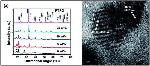 | ||
| Fig. 1 (a) XRD patterns of pure PVDF, PVDF/PTFO nanocomposites and pure PTFO nanoparticles; (b) HR-TEM image of PTFO nanoparticle. | ||
Fig. 1b shows the HRTEM image of PTFO nanoparticle, which clearly indicates crystal domain with interplanar spacing of ∼0.400 nm and ∼0.281 nm corresponding to the (001) and (101) plane respectively.
The photographic images of pure PVDF and PVDF/PTFO (25 wt% PTFO) nanocomposite film is shown in Fig. 2. It is observed that PTFO-loaded PVDF film exhibits excellent flexibility as of pure PVDF film, which is a criterion crucial for the fabrication of new devices.
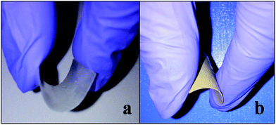 | ||
| Fig. 2 Photographic images of (a) pure PVDF and (b) PVDF/PTFO (25 wt%) nanocomposite film, showing excellent flexibility associated with both the films. | ||
Fig. 3 shows the morphology of PVDF/PTFO nanocomposites, wherein the PTFO nanoparticles were homogeneously dispersed in the PVDF matrix with no obvious pores. It may be commented that the dispersion extent of PTFO nanoparticles is predominantly of smaller ‘agglomerates’ in the corresponding nanocomposite, irrespective of the concentration of the PTFO nanoparticles.
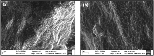 | ||
| Fig. 3 SEM images of fractured surfaces of PVDF/PTFO nanocomposite of (a) 10 wt% of PTFO and (b) 25 wt% of PTFO. | ||
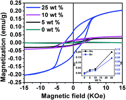
The magnetic hysteresis loops (M–H isotherms) of the PVDF/PTFO nanocomposite samples at room temperature are depicted in Fig. 4. Saturated magnetic hysteresis loops are observed for all nanocomposite films (5, 10 and 25 wt% of PTFO level), confirming their ferromagnetic nature. Moreover, as shown in the inset of Fig. 4, saturation magnetization (Ms) is increased as a function of PTFO concentration in the nanocomposite films. The increase in magnetization may be explained as follows: (i) the non-magnetic PVDF polymer coating layer can be observed as a magnetic dead layer on the surface of the PTFO nanoparticles, which affects the magnitude of magnetization, caused by the quenching of the surface moment;35 and (ii) on increasing the weight fraction of the PTFO nanoparticles, the weight fraction of the non-magnetic PVDF phase is decreased in the nanocomposite film, thereby increasing the total magnetization.
The observed magnetization in PVDF/PTFO nanocomposite of 25 wt% PTFO nanoparticles is ten times higher than that reported for hot-pressed PVDF/BiFeO3 composite films19 and is comparable with PMMA/BiFeO3, PVAc/BiFeO3 (ref. 22) and PVA/BiFeO3 (ref. 23) nanocomposite films prepared by solution casting technique. In the present context, the ten-fold increase in magnetization value in PVDF/PTFO nanocomposite of 25 wt% PTFO nanoparticles could be attributed to the superior magnetic properties of PTFO24 as compared to BiFeO3. The magnetization of Fe3O4 loaded PVDF,39 PVDF–GO (graphene oxide)–Fe3O4 (ref. 40) nanocomposite systems and PVDF/Ni nanohybrid41 are higher than our PVDF/PTFO nanocomposite sample of 25 wt% of PTFO nanoparticles, because Fe3O4 and Ni are known to be strong magnetic materials, while PTFO is made magnetic by doping of Fe at Ti site in PbTiO3 system; which is basically ferroelectric. Hence, this behavior is well understood.
The ferroelectric hysteresis loops of pure PVDF and PVDF/PTFO nanocomposite films are obtained at measuring frequency of 100 Hz at room temperature (Fig. 5). The maximum polarization obtained in PVDF/PTFO nanocomposite film of 5, 10 and 25 wt% of PTFO nanoparticles are ∼0.04, 0.07 and 0.1 μC cm−2, which are higher than that of the pure PVDF with a polarization of ∼0.03 μC cm−2. The values of maximum polarization (Pm), remanent polarization (Pr) and coercive field (Ec) are increased with increase in the PTFO concentration in the respective nanocomposite sample. The low Pr and Pm values for the nanocomposite are primarily attributed to the lowering of the effective electric field on PTFO by the low-permittivity of the surrounding polymer matrix. However, the observed values of maximum polarization and remanent polarization in PVDF/PTFO nanocomposite of 25 wt% PTFO nanoparticles are nearly three orders of magnitude higher as compared to those reported for PVA/BiFeO3 nanocomposite film,23 while the values are less compared to the results reported for PVDF/BaTiO3 composite sheets prepared by hot rolling37 and hot pressing technique,38 and comparable with the results reported for PVDF/BaTiO3 composite of 70 wt% BaTiO3, prepared by Muralidhar et al.42 The observed values of maximum polarization and remanent polarization in 25 wt% PVDF/PTFO samples are nearly twice of those reported for Fe3O4 loaded PVDF,39 PVDF–GO (graphene oxide)–Fe3O4 (ref. 40) nanocomposite systems, which reported that the addition of GO or Fe3O4 or both leads to crystal transformation of PVDF phase into ferroelectric β-phase.
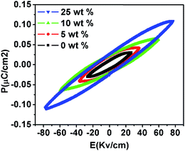 | ||
| Fig. 5 Variation in polarization as a function of the applied electric field (P–E hysteresis loops) at room temperature. | ||
In this context, it is to be noted that further scope of improving the ferroelectric characteristic is remaining in context to PVDF/PTFO nanocomposites by using stretching and suitable poling method and optimizing the filler loading, which may eventually lead to β-phase of the PVDF.
Fig. 6a and b show the dielectric permittivity (ε′) and dielectric loss (tan![[thin space (1/6-em)]](https://www.rsc.org/images/entities/char_2009.gif) δ) of the PVDF/PTFO nanocomposite films as a function of the PTFO concentration, measured at frequencies ranging from 10 Hz to 10 MHz at room temperature. It is observed from Fig. 6a, that dielectric permittivity is increased with the increasing concentration of PTFO nanoparticles. The increase in dielectric permittivity is clearly caused by the increasing contribution of PTFO nanoparticles to the dielectric properties of the corresponding nanocomposite as PTFO nanoparticles register a dielectric permittivity substantially higher than that of PVDF. The variation in the dielectric permittivity with increase in frequency for the respective nanocomposite is observed to be similar as that of pure PVDF. At frequencies ranging from 10 to 100 Hz, the dielectric loss was high, confirming the existence of interfacial polarization originating from signature relaxation. A slow variation is observed for the dielectric loss tangent at frequencies ranging from 103 to 105 Hz, followed by an increase to a sharp peak around 107 Hz, attributed to the glass transition relaxation of the PVDF matrix; this relaxation is denoted as α-relaxation.36,43
δ) of the PVDF/PTFO nanocomposite films as a function of the PTFO concentration, measured at frequencies ranging from 10 Hz to 10 MHz at room temperature. It is observed from Fig. 6a, that dielectric permittivity is increased with the increasing concentration of PTFO nanoparticles. The increase in dielectric permittivity is clearly caused by the increasing contribution of PTFO nanoparticles to the dielectric properties of the corresponding nanocomposite as PTFO nanoparticles register a dielectric permittivity substantially higher than that of PVDF. The variation in the dielectric permittivity with increase in frequency for the respective nanocomposite is observed to be similar as that of pure PVDF. At frequencies ranging from 10 to 100 Hz, the dielectric loss was high, confirming the existence of interfacial polarization originating from signature relaxation. A slow variation is observed for the dielectric loss tangent at frequencies ranging from 103 to 105 Hz, followed by an increase to a sharp peak around 107 Hz, attributed to the glass transition relaxation of the PVDF matrix; this relaxation is denoted as α-relaxation.36,43
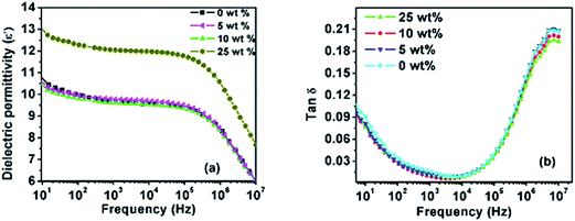 | ||
Fig. 6 Variation in the dielectric permittivity (a) and dielectric loss (tan![[thin space (1/6-em)]](https://www.rsc.org/images/entities/char_2009.gif) δ) (b) with increase in frequency for PVDF/PTFO nanocomposites at room temperature. δ) (b) with increase in frequency for PVDF/PTFO nanocomposites at room temperature. | ||
The dielectric permittivity of pure PVDF and PVDF/PTFO nanocomposite of 25 wt% PTFO nanoparticles at 1 kHz register 9.7 and 12 respectively. The dielectric loss value of pure PVDF and the corresponding PVDF/PTFO nanocomposite samples at 1 kHz register 0.015 and 0.0109 respectively. The observed dielectric permittivity in pure PVDF sample is more than two times higher than the reported results of Luo et al. for pure PVDF film, prepared by solution casting method.36 Furthermore, the value of dielectric loss in our pure PVDF film (0.0109) is significantly lower than those achieved for pure PVDF film (∼0.06) by the same author.
The value of dielectric permittivity of PVDF/PTFO nanocomposite sample of 25 wt% PTFO nanoparticles at 1 kHz is 12, which is significantly higher as compared to the reported values for PVAc/BiFeO3,22 BiFeO3/PMMA,21 PVDF–GO–Fe3O4 nanocomposite films.40
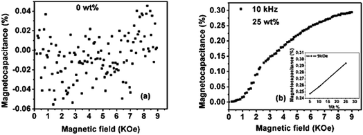
Magneto-dielectric (or magneto-capacitance) measurement is a way utilized for characterizing the degree of the coupling between magnetic and dielectric properties. The variation in the dielectric permittivity (or capacitance) with the applied magnetic field is characterized by the magneto-capacitive parameter, which is defined as MD = {(ε(H) − ε(0))/ε(0)} × 100%, where ε(H) and ε(0) represent the dielectric permittivity in the presence and absence of the applied magnetic field, respectively. Fig. 7a and b show the value of the magneto-capacitive parameter at room temperature, as a function of the applied magnetic field for pure PVDF and PVDF/PTFO nano-composite film of 25 wt% PTFO content respectively. As expected, magneto-capacitance is not observed for pure PVDF film. The value of dielectric constant is increased with applied magnetic field for the nanocomposite film of 25 wt% PTFO content, indicating a positive magneto-capacitance effect. Magneto-dielectric coupling is increased with increase in the concentration of PTFO nanoparticles (inset of Fig. 7b). The magneto-dielectric coupling coefficient (magneto-capacitive parameter) at room temperature is found to be 0.3% for the PVDF/PTFO nano-composite film of 25 wt% PTFO content at 9 kOe of applied magnetic field and at 10 kHz frequency.
Fig. 8 shows the frequency dependence of AC electrical conductivity for the PVDF/PTFO nanocomposite films. AC electrical conductivity is increased with increase in frequency. The frequency-dependent component of AC electrical conductivity is expressed by σfre(T) = A(T) × ωη(T),44 where ‘A’ is the pre-exponential factor, and ‘η’ is the universal exponent such that 0 < η < 1. The DC electrical conductivity of all samples is found to be in the order of 10−12 S cm−1. The ‘η’ value for the PVDF/PTFO nanocomposite films is 0.97 ± 0.002 at room temperature (inset in Fig. 8).
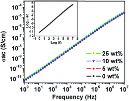 | ||
Fig. 8 Frequency dependent AC electrical conductivity for the PVDF/PTFO nanocomposite films. Inset shows the determination of ‘n’ by fitting the linear plot of log![[thin space (1/6-em)]](https://www.rsc.org/images/entities/char_2009.gif) σAC versus log(f). σAC versus log(f). | ||
Further, our results also indicate an improvement in magnetodielectric coupling nearly one order of magnitude higher than that reported for PVDF–GO–Fe3O4 nanocomposite film (∼0.02),40 nearly sixty times higher as compared to PVDF–Ni composite film (∼0.005%),41 and three times higher as compared to Fe3O4 loaded PVDF nanocomposite film (∼0.1%).39 The magneto-dielectric coupling for PVDF/PTFO nanocomposite film of 25 wt% PTFO content is also nearly three times higher than that observed in PVAc/BiFeO3 nanocomposite films (<0.1%), prepared via solution casting method.22
The observed improvement in ferroelectric, dielectric and magneto-dielectric properties is attributed to significantly low loss and low electrical conductivity of PVDF/PTFO nanocomposite sample, which might be caused by better interconnectivity and dispersion of nanoparticles in the host polymer matrix. It is anticipated that multiferroic PTFO grains (PTFO nanoparticles) could be interconnected via the flexible PVDF matrix, which shows ferroelectric behaviour (piezoelectric properties), thereby serving as a strain-transferring medium between the multiferroic grains within PVDF/PTFO nanocomposite film, which in turn might result in enhanced magnetoelectric response as well. These nanocomposite flexible films may therefore display significant ME coupling. The results obtained for PVDF/PTFO nanocomposite samples with different PTFO concentration are summarized in the ESI of Table 1.† The results are also compared with the existing literature; (see the ESI of Table 2†).
It is to be noted that the β-phase exhibits ferroelectric behaviour and registers the largest piezoelectric response among all polymorphs of PVDF. The polar β-phase is desirable and usually achieved by uniaxial or biaxial stretching of α-phase films at temperatures between 70 °C and 100 °C and stretch ratios larger than four.30 β-phase films can also be obtained by crystallization from dimethyl formamide (DMF) or dimethyl acetamide solutions at temperature below 70 °C, but the resulting films are porous and fragile.45 Some other methods to obtain β-PVDF phase could be via crystallization under high pressure or by the use of copolymers such as poly(vinylidene trifluoroethylene) (PVDF-TrFE) or by the addition of nanoparticles into PVDF matrix for nucleation of the β-PVDF phase.46 It is to be noted that we could obtain the β-phase (via the signature of the WAXD pattern) in pure PVDF as well as PVDF/PTFO nanocomposites via injection molding technique, which was absent in case of the compression molded sample of the corresponding nanocomposite. Further investigation will be made to understand the role of stretching as well as poling in the development of the β-phase in PVDF/PTFO nanocomposites.
Conclusion
Flexible films of PVDF/PTFO nanocomposites were prepared, wherein PTFO concentration was varied from 5–25 wt%. The structure, magnetic, ferroelectric, as well as dielectric and magneto-dielectric properties of the corresponding nanocomposites were investigated. The nanocomposite films exhibited ferromagnetic and ferroelectric, an enhanced dielectric and low loss properties with significant magnetodielectric coupling. It should be emphasized that the processing temperature of the nanocomposite was much lower as compared to pure ceramic materials, which is a great advantage, because of the compatibility with silicon technology and low melting temperature substrates. Thus, these films could find applications in smart devices, in which magneto-dielectric coupling and multifunctional behaviour can be exploited in addition to the flexibility. Moreover, the prepared multiferroic flexible films may reflect the possibility for fabricating wearable devices based on multiferroic materials.Acknowledgements
The authors wish to acknowledge ‘Microcompounder Central Facility’, ‘Broadband Dielectric Spectroscopy Central facility’ at IIT Bombay for conducting dielectric and magneto-dielectric measurements.References
- L. D. Landau, J. S. Bell, M. J. Kearsley, L. P. Pitaevskii, E. M. Lifshitz and J. B. Sykes, Electrodynamics of Continuous Media, Pergamon Press, Oxford, 2nd edn, 1960 Search PubMed.
- T. Zhao, A. Scholl, F. Zavaliche, K. Lee, M. Barry, A. Doran, M. P. Cruz, Y. H. Chu, C. Ederer, N. A. Spaldin, R. R. Das, D. M. Kim, S. H. Baek, C. B. Eom and R. Ramesh, Nat. Mater., 2006, 5, 823–829 CrossRef CAS PubMed.
- V. R. Palkar, K. G. Kumara and S. K. Malik, Appl. Phys. Lett., 2004, 84, 2856–2858 CrossRef CAS.
- M. Bibes and A. Barthelemy, Nat. Mater., 2008, 7, 425–426 CrossRef CAS PubMed.
- M. M. Kumar, V. R. Palkar, K. Srinivas and S. V. Suryanarayana, Appl. Phys. Lett., 2000, 76, 2764–2766 CrossRef CAS.
- V. R. Palkar, J. John and R. Pinto, Appl. Phys. Lett., 2002, 80, 1628–1630 CrossRef CAS.
- G. Catalan and J. F. Scott, Adv. Mater., 2009, 21, 2463–2485 CrossRef CAS.
- J. van Suchtelen, Philips Res. Rep., 1972, 27, 28–37 Search PubMed.
- H. Ryu, P. Murugavel, J. H. Lee, S. C. Chae, T. W. Noh, Y. S. Oh, H. J. Kim, K. H. Kim, J. H. Jang, M. Kim, C. Bae and J.-G. Park, Appl. Phys. Lett., 2006, 89, 102907 CrossRef.
- A. D. Sheikh and V. L. Mathe, J. Phys. Chem. Solids, 2011, 72, 1423–1429 CrossRef CAS.
- C.-W. Nan, N. Cai, L. Liu, J. Zhai, Y. Ye and Y. Lin, J. Appl. Phys., 2003, 94, 5930–5936 CrossRef CAS.
- Y. Wang, S. W. Or, H. L. W. Chan, X. Zhao and H. Luo, J. Appl. Phys., 2008, 103, 124511 CrossRef.
- C. Nayek, K. K. Sahoo and P. Murugavel, Mater. Res. Bull., 2013, 48, 1308–1311 CrossRef CAS.
- T. X. Li, M. Zhang, F. J. Yu, Z. Hu, K. S. Li, D. B. Yu and H. Yan, J. Phys. D: Appl. Phys., 2012, 45, 085002 CrossRef.
- J.-p. Zhou, H. He, Z. Shi and C.-W. Nan, Appl. Phys. Lett., 2006, 88, 013111 CrossRef.
- P. Martins and S. Lanceros-Méndez, Adv. Funct. Mater., 2013, 23, 3371–3385 CrossRef CAS.
- S. Jiansirisomboon, K. Songsiri, A. Watcharapasorn and T. Tunkasiri, Curr. Appl. Phys., 2006, 6, 299–302 CrossRef.
- K. J. Loh and D. Chang, J. Mater. Sci., 2010, 46, 228–237 CrossRef.
- A. V. Reddy, K. C. Sekhar, N. Dabra, A. Nautiyal, J. S. Hundal, N. P. Pathak and R. Nath, ISRN Mater. Sci., 2011, 2011, 142968 Search PubMed.
- D. Bhadra, M. G. Masud, S. Sarkar, J. Sannigrahi, S. K. De and B. K. Chaudhuri, J. Polym. Sci., Part B: Polym. Phys., 2012, 50, 572–579 CrossRef CAS.
- A. Ahlawat, S. Satapathy, S. Bhartiya, M. K. Singh, R. J. Choudhary and P. K. Gupta, Appl. Phys. Lett., 2014, 104, 042902 CrossRef.
- O. P. Bajpai, J. B. Kamdi, M. Selvakumar, S. Ram, D. Khastgir and S. Chattopadhyay, eXPRESS Polym. Lett., 2014, 8, 669–681 CrossRef CAS.
- J. S. Hwang, J. Y. Cho, S. Y. Park, Y. J. Yoo, P. S. Yoo, B. W. Lee and Y. P. Lee, Appl. Phys. Lett., 2015, 106, 062902 CrossRef.
- V. R. Palkar and S. K. Malik, Solid State Commun., 2005, 134, 783–786 CrossRef CAS.
- V. R. Palkar, S. C. Purandare, S. Gohil, J. John and S. Bhattacharya, Appl. Phys. Lett., 2007, 90, 172901 CrossRef.
- K. I. Doig, J. J. P. Peters, S. Nawaz, D. Walker, M. Walker, M. R. Lees, R. Beanland, A. M. Sanchez, C. F. McConville, V. R. Palkar and J. Lloyd-Hughes, Sci. Rep., 2015, 5, 7719 CrossRef CAS PubMed.
- S. Aggarwal, R. Pinto and V. R. Palkar, J. Phys. D: Appl. Phys., 2016 Search PubMed , under review.
- A. J. Lovinger, Developments in Crystalline Polymers—1, ed. D. C. Bassett, Springer, Netherlands, 1982, pp. 195–273 Search PubMed.
- K. P. Pramoda, A. Mohamed, I. Yee Phang and T. Liu, Polym. Int., 2005, 54, 226–232 CrossRef CAS.
- V. Sencadas, R. Gregorio and S. Lanceros-Méndez, J. Macromol. Sci., Part B: Phys., 2009, 48, 514–525 CrossRef CAS.
- P. Barber, S. Balasubramanian, Y. Anguchamy, S. Gong, A. Wibowo, H. Gao, H. J. Ploehn and H.-C. Z. Loye, Materials, 2009, 2, 1697–1733 CrossRef CAS.
- Y. Osada and D. E. De Rossi, Polymer Sensors and Actuators, Springer, Berlin, 2013 Search PubMed.
- J. Kymissis, C. Kendall, J. Paradiso and N. Gershenfeld, Wearable Computers, 1998 Digest of Papers Second International Symposium on, 1998, pp. 132–139 Search PubMed.
- C. Thirmal, C. Nayek, P. Murugavel and V. Subramanian, AIP Adv., 2013, 3, 112109 CrossRef.
- R. Kaiser and G. Miskolczy, J. Appl. Phys., 1970, 41, 1064–1072 CrossRef CAS.
- B. Luo, X. Wang, Y. Wang and L. Li, J. Mater. Chem. A, 2014, 2, 510–519 CAS.
- R. Sharma, I. P. Singh, A. K. Tripathi and P. K. C. Pillai, J. Mater. Sci., 1994, 29, 995–998 CrossRef CAS.
- Y. P. Mao, S. Y. Mao, Z.-G. Ye, Z. X. Xie and L. S. Zheng, J. Appl. Phys., 2010, 108, 014102 CrossRef.
- O. D. Jayakumar, B. P. Mandal, J. Majeed, G. Lawes, R. Naik and A. K. Tyagi, J. Mater. Chem. C, 2013, 1, 3710–3715 RSC.
- O. D. Jayakumar, E. H. Abdelhamid, V. Kotari, B. P. Mandal, R. Rao Jagannath, R. Naik and A. K. Tyagi, Dalton Trans., 2015, 44, 15872–15881 RSC.
- B. P. Mandal, K. Vasundhara, E. Abdelhamid, G. Lawes, H. G. Salunke and A. K. Tyagi, J. Phys. Chem. C, 2014, 118, 20819–20825 CAS.
- C. Muralidhar and P. K. C. Pillai, J. Mater. Sci. Lett., 1987, 6, 1243–1245 CrossRef CAS.
- K. Yu, H. Wang, Y. Zhou, Y. Bai and Y. Niu, J. Appl. Phys., 2013, 113, 034105 CrossRef.
- A. K. Jonscher, Nature, 1975, 253, 717–719 CrossRef CAS.
- P. Martins, C. M. Costa, M. Benelmekki and S. Lanceros-Mendez, Sensor Lett., 2013, 11, 110–114 CrossRef CAS.
- V. Sencadas, P. Martins, A. Pitães, M. Benelmekki, J. L. Gómez Ribelles and S. Lanceros-Mendez, Langmuir, 2011, 27, 7241–7249 CrossRef CAS PubMed.
Footnote |
| † Electronic supplementary information (ESI) available. See DOI: 10.1039/c6ra01306f |
| This journal is © The Royal Society of Chemistry 2016 |

