DOI:
10.1039/C6RA01175F
(Paper)
RSC Adv., 2016,
6, 28435-28441
Gram-grade Cr(VI) adsorption on magnetite/carbon hybrid architectures
Received
14th January 2016
, Accepted 9th March 2016
First published on 11th March 2016
Abstract
In this work, two-dimensional magnetite/carbon (Fe3O4@C) hybrid architectures were fabricated by a feasible template method via thermal treatment. The Fe3O4 nanoparticles were tightly embedded into the carbon sheets in the form of well-ordered arrays and disordered assembly. These architectures were then employed to remove Cr(VI) ions from water. Whatever the arrangement of Fe3O4 nanoparticles in the carbon sheets, the maximum Cr(VI) adsorption capacities were found to be around 1100 mg g−1 above 308 K in the pH range of 4.84–5.83. These values, to our knowledge, were much larger than those reported for metal-oxide adsorbents and activated carbons in the previous literature. More strikingly, these adsorbents can be easily separated from water by using a magnet. The high Cr(VI) adsorption capacities at different temperatures and easy separation are highly promising for their widespread potential applications in water treatment.
1. Introduction
Heavy metal ions, such as Pb(II), As(III), and Cr(VI), are recognized to be main toxic contaminants in wastewater, which can induce serious side effects (e.g., human genetic material mutations, tumor and abnormal embryonic development) when their concentrations are beyond permissible limits. Therefore, it is important to purify the effluent before disposing it into the environment. Several methods have been employed for the removal of metal ions from wastewater, such as chemical precipitation,1 ion exchange,2 electrolytic methods,3 membrane filtration and reverse osmosis methods.4 However, most of the aforementioned methods have been found, to varying degrees, to be limited due to their high cost and low efficiency. The adsorption technique is versatile because of its low cost, easy operation, high efficiency,5–11 and strong ability to selectively remove the pollutants up to low concentration levels. The traditional absorbents, such as activated carbon, clay, and zeolite, show limited adsorption abilities for heavy metal ions. For example, common activated carbons are of high specific surface area (SSA) from 500 to 1700 m2 g−1, and hence can be used as mainstream absorbents. Nonetheless, it is difficult to be separated from water and hence may cause serious secondary pollution. Alternatively, owing to their low cost, environmental benignity and easy separation,12 magnetic iron oxides are widely employed to remove heavy metal ions from wastewater. But they also have conspicuous shortcomings including large densities and inferior adsorption abilities to conventional activated-carbon adsorbents.
Because of the complementary advantages and disadvantages of activated carbons and magnetic iron oxides, unremitting efforts have been devoted to combining these two types of materials into composite architectures. Zhou et al. employed a two-step seed emulsion polymerization route to fabricate high-SSA (386.7 mg g−1) magnetic porous carbon microspheres, which can be easily separated from wastewater by a magnetic field after quick adsorption to methylene blue.13 Zhang and Wang fabricated Fe3O4@C@layered double hydroxide (Fe3O4@C@Ni–Al LDH) by a two-step layer-by-layer route. The resultant product has been used for the removal of uranium(VI) from water.14 Despite these progresses, present fabrication routes are often tedious with low yield and high cost.
Herein, two-dimensional (2-D) high-yield Fe3O4@C architectures were fabricated by a feasible template method via thermal treatment. These products were then employed to remove Cr(VI) ion from water. The kinetic and equilibrium studies on Cr(VI) adsorption have been thoroughly investigated.
2. Experimental
2.1 Synthesis of Fe3O4@C architectures
Fe3O4@C architectures were fabricated according to the method proposed by Jang with a little modification. Typically, 0.36 g of iron(III) chloride hexahydrate was dissolved into 1.0 mL of de-ionized water and then mixed with 1.22 g of sodium oleate. The resulting mixture was aged at 85 °C for 3 h, and then was mixed with 4 g of sodium chloride and 10 g of sodium sulfate powders separately. After that, the mixtures were both heated to 600 °C at a heating rate of 5 °C min−1 under N2 atmosphere and kept at that temperature for 3 h. After cooling down to room temperature naturally, the products were washed with de-ionized water and absolute ethanol, and finally dried in the air at 60 °C for 6 h. For simplicity, the as-obtained products are labelled as S1 and S2 for NaCl and Na2SO4 templates, respectively.
2.2 Characterization
The XRD patterns were recorded on a powder X-ray diffractometer (Rigaku D/max-rA; Japan) equipped with a rotating anode and a Cu-Kα1 radiation source (λ = 1.5406 Å) at a step width of 0.02°. Scanning electron microscope (SEM) images were collected on a field-emission scanning electron microscope (JEOL JSM-6700F, Japan). Transmission-electron microscope (TEM) images were performed on the JEOL 2010 TEM (Japan) with an operating voltage of 200 kV. The high-resolution transmission-electron microscope (HRTEM) experiments were conducted using a Field Emission Gun (FEG) JEOL 2010F microscope (Japan) with a point resolution of 0.19 nm. The N2 adsorption and desorption isotherms were conducted using a Quantachrome Instruments, NOVA 1000e. The iso-electric points (IEP) of the samples were measured by testing the zeta-potential in aqueous solution on a Zeatsizer Nano ZS (Malvern Instruments). Surface charge densities were determined by conductometric titration method. Thermo gravimetric analyses (TGA) were performed on a TGA Q500 analyzer with a heating rate of 10 °C min−1 in the air. Fourier transform infrared (FTIR) spectra were performed on KBr disks of the powdered samples using a BRUKER TENSOR 27 FTIR spectrometer.
2.3 Adsorption measurements
Solutions with different Cr(VI) concentrations were prepared using K2Cr2O7 as the source of heavy metal ions. For the adsorption kinetic study of Cr(VI), 40 mg as-prepared product was added into 60 mL Cr(VI) solution with initial Cr(VI) concentration of 25 mg L−1 for different adsorbing time. To obtain the adsorption equilibrium isotherms, 20 mg as-prepared product was added into a set of 30 mL Cr(VI) solutions with different Cr(VI) concentrations, and vigorously stirred for 12 h at four different temperatures (T = 303, 308, 313 and 323 K). No pH buffers were used during the adsorption experiments and all the equilibrium pH values were measured between 4.84 and 5.83. After adsorption, the adsorbent was immediately separated by centrifugation from Cr(VI) solutions. Subsequently, Cr(VI) concentrations in supernatant were determined by inductively coupled plasma-optical emission spectrometer (ICP-OES, Perkin-Elmer, Optima 8000). To investigate the effect of pH value on Cr(VI) adsorption, pH values of solutions (Cr(VI), 100 mg L−1) after adsorbents addition were adjusted to 3, 5, 7, 9 and 11 at room temperature by using 0.1 mol L−1 HCl or NaOH solutions.
2.4 Desorption and regeneration
In order to evaluate the reusability of Fe3O4@C architectures, desorption experiments using NaOH were carried out. After saturated adsorption, the Cr(VI)-loaded Fe3O4@C architectures were separated from the solution by an external magnetic field. The exhausted adsorbents were reintroduced to the desorption medium and agitated by a stirring paddle for 120 min at 303 K. After each cycle of recovery, regenerated Fe3O4@C architectures were washed with deionized water and dried for reuse.
3. Results and discussion
3.1 Fe3O4@C architectures
The chemical composition of the as-obtained products (S1 and S2) is shown in Fig. 1a, in which all the diffraction peaks can be assigned to cubic Fe3O4 (JCPDS No. 65-3107) phase. The characteristic peaks of carbon phase are inconspicuous due to its amorphous character and low intensity. Fig. 1b and c show Fe3O4 nanoparticles (NPs) are unambiguously embedded into micro-sized carbon sheets, resulting in rough textures for both products. But upon closer scrutiny, the assembly of Fe3O4 NPs is quite different for S1 and S2. Apparently, the morphology of S1 reveals an ordered assembly of Fe3O4 NPs, while the Fe3O4 NPs in S2 are unevenly distributed. This structural deviation is probably attributed to the type and amount of template used in fabrication. The SEM images of NaCl and Na2SO4 templates are shown in Fig. 1d and e, respectively. Compared to the cube-like morphology of NaCl, the shape of Na2SO4 template is rather irregular. Most importantly, the amount of Na2SO4 template is 10 g, which is two times larger than that of NaCl template. In this case, the concentration of iron ions per unit area of Na2SO4 template is much lower than that of NaCl template, with the amount of precursor held constant. The lower concentration of iron ions per unit area, the greater tendency for Fe3O4 NPs to grow. Otherwise, the higher concentration of iron ions per unit area, the greater tendency for Fe3O4 NPs to nucleate. Those being the case, it is expected that iron ions at NaCl surfaces have the priority to nucleate due to their high concentration, and finally yield orderly-distributed Fe3O4 NPs with immature exposed facets of high energy. By contrast, iron ions at Na2SO4 surfaces prefer to grow into disordered Fe3O4 NPs with low-energy facets.
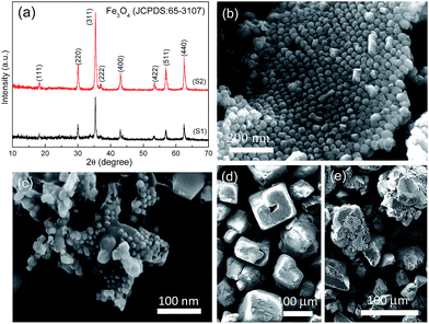 |
| | Fig. 1 (a) XRD patterns of the as-obtained products (S1 and S2). SEM images of (b) S1, (c) S2 products and (d) NaCl, (e) Na2SO4 templates. | |
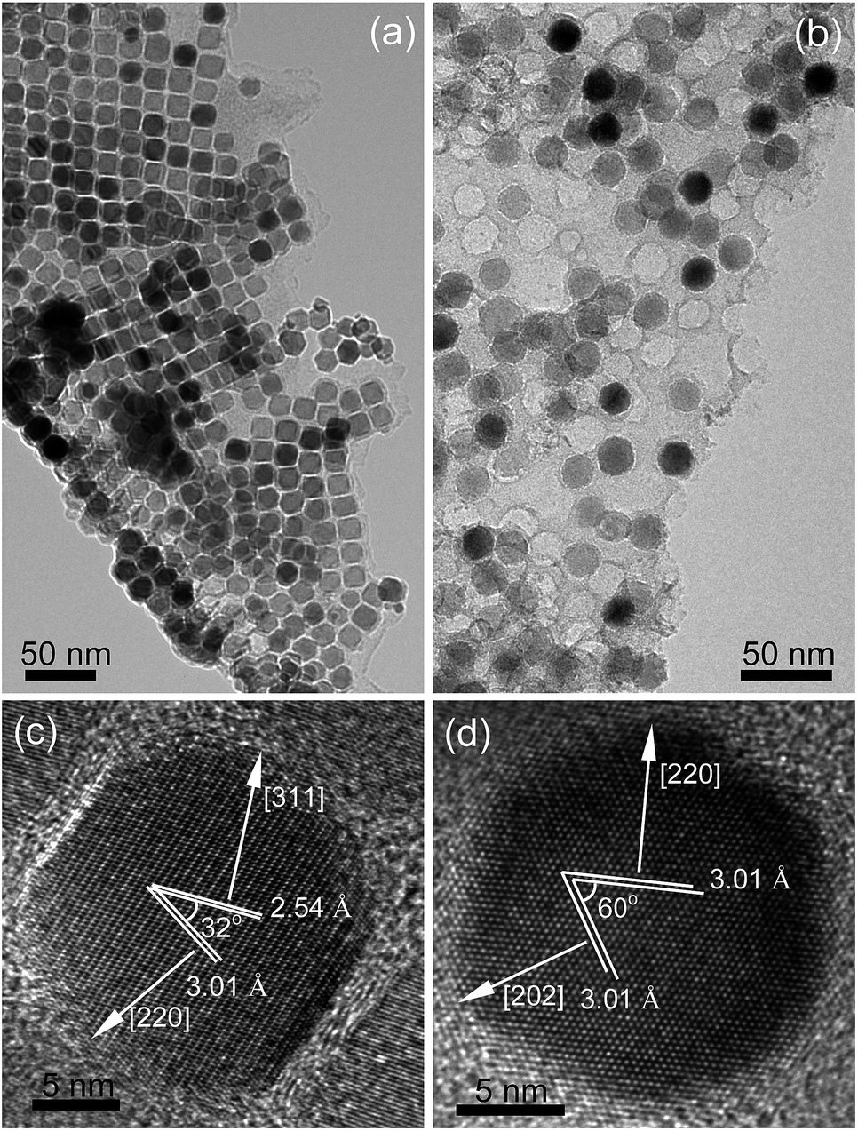
The TEM images in Fig. 2a and b further evidence the morphology and size nuance of Fe3O4 NPs between S1 and S2. With regard to S1, Fe3O4 NPs are almost cube-like with an averaging edge length of 16 nm. In contrast, Fe3O4 NPs in S2, being of ca. 22 nm in size, are virtually hexagonal-shaped. Moreover, HRTEM images in Fig. 2c and d show the indices of exposed facets of Fe3O4 NPs belong to {112} and {111} for S1 and S2, respectively, which correspond to the high- and low-energy crystallographic planes in Fe3O4 lattice.
 |
| | Fig. 2 TEM and HRTEM images of (a and c) S1 and (b and d) S2. | |
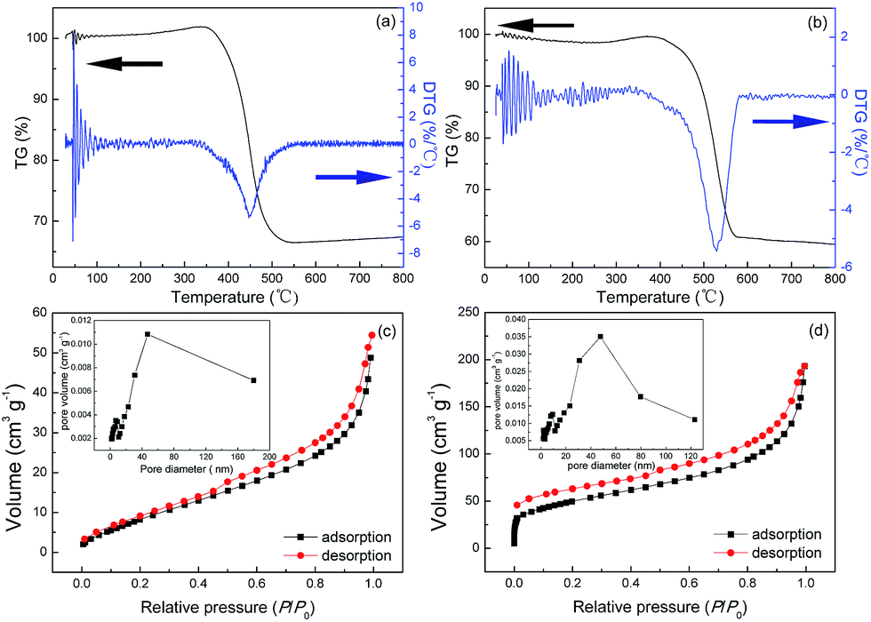
To evaluate the weight percent of Fe3O4 in these two Fe3O4@C architectures, typical TGA thermograms were studied. Fig. 3a and b show that these TGA curves exhibit creeping increase at 300–400 °C and 350–450 °C for S1 and S2, respectively. These weight gains are attributed to the partial oxidation of Fe3O4 phase to more stable α-Fe2O3 phase in the air. After that, the steep weight loss around 400–500 °C and 450–550 °C (for S1 and S2, respectively) can be due to the full oxidation of carbon, leaving residual α-Fe2O3 phase. Based on these analyses, the weight percent of Fe3O4 in S1 and S2 can be estimated to be 33.73 and 30.86, respectively. It is also shown from the differential thermo gravimetric (DTG) curves in Fig. 3a and b that the biggest weight-loss temperatures of S1 and S2 are determined around 450 and 540 °C, respectively. Collectively, the lower weight-gain and weight-loss temperatures of S1 indicate its stronger chemical activity to oxidation, which is probably ascribed to the higher catalytic activity of Fe3O4 NPs with high-energy facets in S1. The higher weight percent of Fe3O4 NPs in S1 endows it with lower Brunauer–Emmett–Teller (BET) surface area of 38.4 m2 g−1, which is calculated from the linear part of N2 adsorption–desorption isotherm in Fig. 3c. Similarly, Fig. 3d shows the BET surface area of S2 is about 174.4 m2 g−1, which is ca. 4.5 times larger than that of the S1. The pore diameters of S1 and S2 both exhibit bimodal distributions (inset in Fig. 3c and d). There exist mesopores with peak diameters of ca. 10 and 40 nm, indicative of porous structures in these architectures.
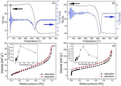 |
| | Fig. 3 TGA and DTG curves of (a) S1 and (b) S2. N2 adsorption–desorption isotherms of (c) S1 and (d) S2. The corresponding pore-size distributions are shown as insets. | |
Fig. 4a and b show FTIR spectra of Fe3O4@C architectures. The broad bands at ca. 3400 cm−1 are attributed to the stretching mode of O–H in adsorbed water. The adsorption peaks at ca. 580 cm−1 are assigned to the stretching vibration of Fe–O bond in Fe3O4. The bands at ca. 1620 and 1385 cm−1 are assigned to the asymmetrical and symmetrical vibration of carboxylate groups, respectively.15 And the separation of ν(COO–) bands is ca. 235 cm−1, which indicates that the carboxylate coordination mode is unidentate.16,17 This confirms that the oleic group was chemisorbed onto the surface by coordination of oxygen atoms in carboxylate and iron atoms of nanoparticles asymmetrically in the growth process of nanoparticles.
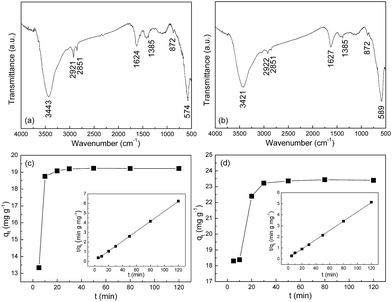 |
| | Fig. 4 FT-IR spectra of (a) S1 and (b) S2. The kinetics of Cr(VI) adsorption on (c) S1 and (d) S2 with an initial concentration of 25 mg L−1 at 303 K. Inset: linear plots of the pseudo-second-order model. | |
3.2 Cr(VI) adsorption
Fig. 4c and d show the adsorption kinetics of Cr(VI) adsorbed on S1 and S2 at 303 K. The adsorption kinetics can be well fitted by a pseudo-second-order model, expressed by eqn 1| |
 | (1) |
where k is the rate constant (g mg−1 min−1), qe is equilibrium adsorption capacity (mg g−1), and qt is the amount of Cr(VI) (mg g−1) adsorbed at time t. After integration, eqn (1) changes to| |
 | (2) |
By plotting t/qt versus t, one can determine the values of qe and k from the slope and intercept of the fitted line, respectively. More strikingly, the initial adsorption rates h, which can be determined by h = kqe2, are up to 23.88 and 15.4 mg g−1 min−1 for S1 and S2, respectively. In addition, the correlation coefficient (R2) values of the fitted plot of the S1 and S2 are nearly unity, indicating the applicability of the pseudo-second-order model for the above adsorption kinetic (Table 1).
Table 1 Fitted parameters of Cr(VI) adsorption kinetics for S1 and S2 at 303 K
| Adsorbents (Fe3O4@C) |
k (g mg−1 min−1) |
qe (mg g−1) |
R2 |
h (mg g−1 min−1) |
| S1 |
0.0634 |
19.406 |
0.999 |
23.88 |
| S2 |
0.0272 |
23.8 |
0.999 |
15.4 |
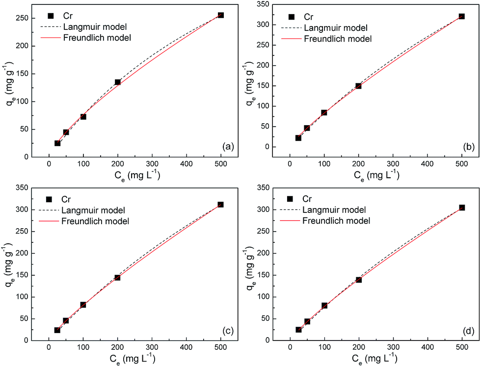
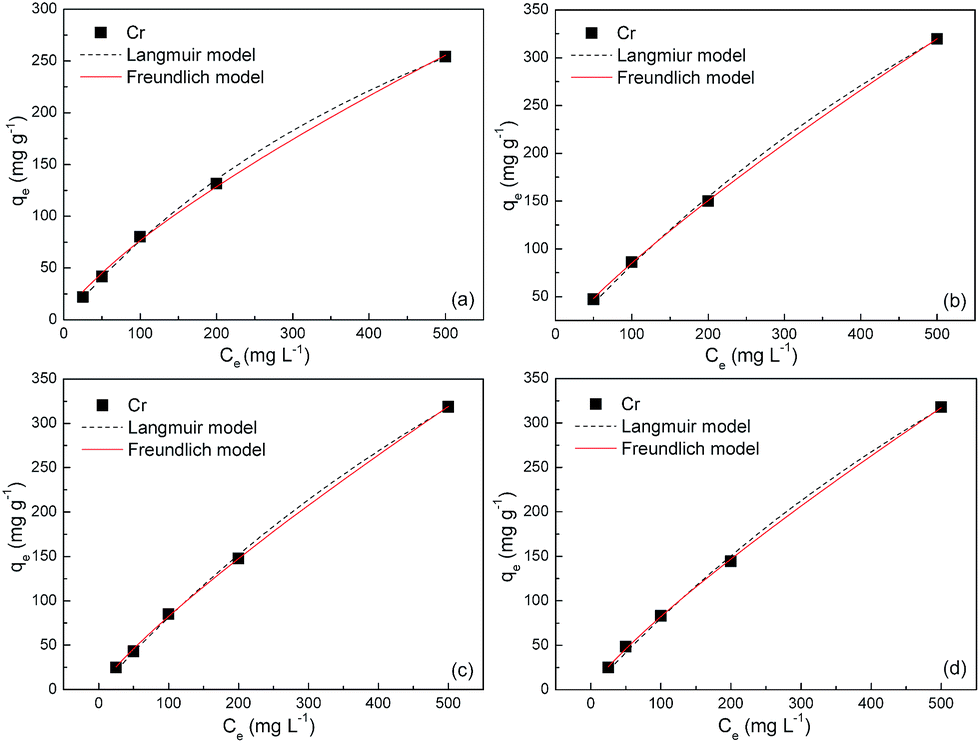
The equilibrium adsorption isotherms in Fig. 5 and 6 are obtained by varying the initial Cr(VI) concentration from 25 to 500 mg L−1 at 303, 308, 313 and 323 K. The Langmuir and Freundlich isotherm models are used to describe these experimental data. The Langmuir model is given by
| |
 | (3) |
where
Ce is the equilibrium concentration of Cr(
VI) in the supernatant (mg L
−1),
KL is the Langmuir adsorption constant related to the affinity of binding sites (L mg
−1) and
qm is the maximum adsorption capacity (mg g
−1).
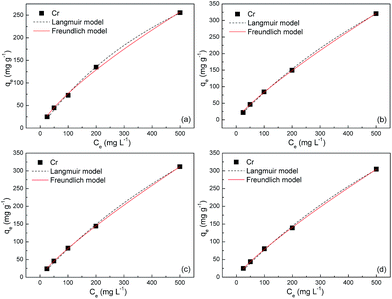 |
| | Fig. 5 Adsorption isotherms of S1 at (a) 303, (b) 308, (c) 313 and (d) 323 K. | |
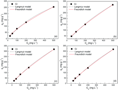 |
| | Fig. 6 Adsorption isotherms of S2 at (a) 303, (b) 308, (c) 313 and (d) 323 K. | |
The Freundlich model assumes that the adsorption capacity is exponentially proportional to the equilibrium concentration
where
KF ((mg g
−1) (L mg
−1)
1/n) and
n (unitless) are Freundlich constants related to the adsorbed Cr(
VI) amount and adsorption affinity, respectively.
The fitted parameters based on these two models are summarized in Table 2. Regardless of the models, the R2 values are very close to unity, indicating that the Langmuir and Freundlich isotherm models are both qualified for the description of adsorption isotherms in this study. The maximum adsorption capacities of S1 are estimated to be ca. 600, 1100, 1170 and 1200 mg g−1 at 303, 308, 313 and 323 K, respectively, which bear striking similarities with that of S2. These values amount to gram-grade, that is, the adsorbed amount of Cr(VI) in this study is roughly equal to the self-weight of Fe3O4@C adsorbents. To our knowledge, these adsorption capacities are highest among those in previous reports for other metal-oxide adsorbents and activated carbons (Table 3). The abrupt increase of adsorption capacities from ca. 600 to ca. 1200 mg g−1 is probably due to the easier chemisorption process at high temperatures. The presence of chemisorption can be validated by the good applicability of the pseudo-second-order model for the adsorption process, which is derived from an assumption that the rate-limiting factor in the adsorption process depends exclusively on chemisorption.
Table 2 Fitted parameters of Cr(VI) adsorption isotherms for S1 and S2
| Adsorbent |
T (K) |
Langmuir model |
Freundlich model |
| KL (L mg−1) |
qm (mg g−1) |
R2 |
KF ((mg g−1) (L mg−1)1/n) |
n |
R2 |
| S1 |
303 |
0.00145 |
603.94 |
0.998 |
2.419 |
1.34 |
0.997 |
| 308 |
0.00081 |
1104.65 |
0.998 |
1.923 |
1.22 |
0.999 |
| 313 |
0.00074 |
1172.80 |
0.998 |
1.711 |
1.19 |
0.999 |
| 323 |
0.00072 |
1196.08 |
0.997 |
1.720 |
1.2 |
0.999 |
| S2 |
303 |
0.0014 |
619.54 |
0.998 |
2.392 |
1.33 |
0.997 |
| 308 |
0.00076 |
1158.93 |
0.998 |
1.743 |
1.2 |
0.999 |
| 313 |
0.00075 |
1133.85 |
0.998 |
1.715 |
1.2 |
0.998 |
| 323 |
0.00071 |
1155.54 |
0.998 |
1.622 |
1.19 |
0.998 |
Table 3 Cr(VI) maximum adsorption capacity for different adsorbents
| Adsorbents |
Temperature (K) |
Adsorption capacity (mg g−1) |
Reference |
| α-Fe2O3 |
293 |
5.4 |
18 |
| Mg–Al-layer |
298 |
183.82 |
19 |
| Fe3O4@C@Ni–Al LDH |
300 |
174 |
14 |
| Graphene@zero-valent iron |
298 |
162 |
20 |
| α-FeOOH |
295 |
58.97 |
21 |
| Cu2O@Cu |
308 |
760 |
22 |
| CTAB modified graphene |
298 |
21.57 |
23 |
| Magnetic cyclodextrin–chitosan–GO |
298 |
61.31 |
24 |
| Aminated wheat straw |
298 |
454 |
15 |
| Fe3O4@C |
308 |
∼1100 |
This work |
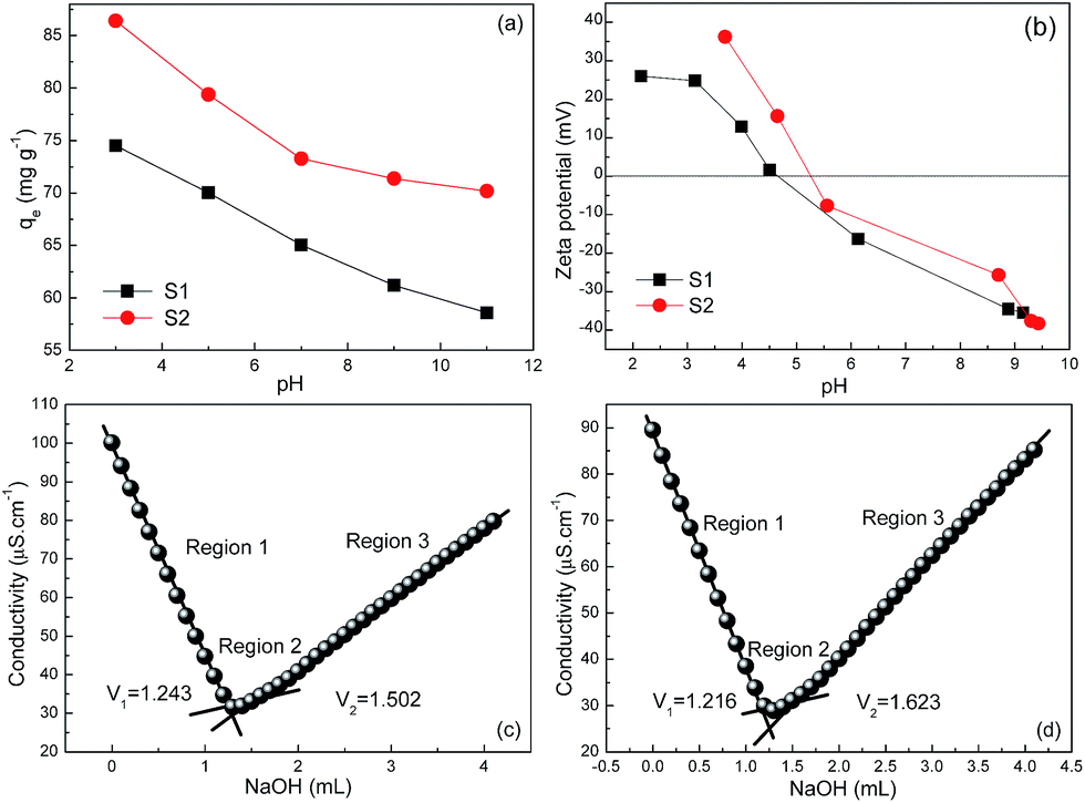
To unravel the fundamental cause of high adsorption capacities of our Fe3O4@C architectures, pH-dependent adsorption experiments were carried out (at pH = 3, 5, 7, 9, 11) with an initial Cr(VI) concentration of 100 mg L−1. Fig. 7a shows the equilibrium adsorption capacity monotonically decreases with an increase of pH value. This variation trend is in excellent consistency with many other literatures25,26 and can be rationally explained by the dependence of zeta potential on pH values in Fig. 7b. The IEP values of S1 and S2 are then determined to be 4.50 and 5.25, respectively. When the pH values are below these IEP values, the positive surface charge would electrostatically attract the Cr(VI) species (Cr2O72− and HCrO4−).26 As increasing the pH values, the ever-increasing deprotonation of the surfaces of S1 and S2 can improve the electrostatic repulsion between the adsorbent and Cr(VI) species, and hence resulting in the decrease of qe values. Given that the pH values in equilibrium adsorption isotherms were measured between 4.84 and 5.83 (close to the IEP values of S1 and S2), the influence of pH values is expected not to be the root cause of the high adsorption capacities in this study.
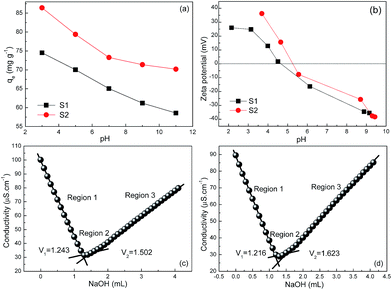 |
| | Fig. 7 (a) Effect of pH values on the equilibrium adsorption capacity for S1 and S2 with initial Cr(VI) concentration of 100 mg L−1. (b) pH-Dependent zeta potential values of S1 and S2 in aqueous solution. Conductometric titration of (c) S1 and (d) S2. | |
Another important factor to affect adsorption capacity is known to be surface charge (OH−) density. Along this line, the surface charge density was directly measured by using a conductometric titration method in this study. Typically, 10 mg of the adsorbent was firstly dispersed into 100 mL of de-ionized water. After adding a certain amount of hydrochloric acid, the solution was titrated with 5 mmol L−1 sodium hydroxide, and meanwhile, its conductivity was recorded. In Fig. 7c and d, one can clearly distinguish three regions by the discontinuities of the experimental curves, which characterize the initial excess of H+ ions (region 1), deprotonation of the –OH2+ groups27 located on the surface of the adsorbent (region 2) and the excess of –OH− (region 3). Surface hydroxyl site densities of S1 and S2 are then calculated to be 0.518 and 0.814 mmol [OH−] g−1, respectively, which are apparently higher than those in previous reports.21,22,28 In this case, the adsorption mechanism of Cr(VI) onto Fe3O4@C architectures can be proposed as follows: (i) at first, the negatively charged Cr2O72− or HCrO4− ions continuously transfer to the vicinity of positively charged Fe3O4@C sheets by electrostatic attraction (i.e., physisorption); (ii) then the enriched Cr2O72−/HCrO4− ions exchange with the hydroxyl groups on Fe3O4@C surfaces and interfaces to promote the adsorption process (i.e., chemisorption).29–31 This will contribute to the high maximum adsorption capacity in this study.
Moreover, to investigate whether there are iron ions release while using these adsorbents in Cr(VI) adsorption, two separate ICP experiments were conducted with regard to two samples. One is K2Cr2O7 aqueous solution before Cr(VI) adsorption, and the other is the supernatant after Cr(VI) adsorption. It was found that iron ions were undetectable in both samples indicating their absence before and after adsorption. Additionally, to apply our adsorbents to practical water treatment, the detection limit (or sensitivity) should be addressed. Given that the maximum contaminant level of chromium in domestic water supplies has been set by World Health Organization (WHO) as 50 μg L−1, thus 60 mL solution with initial Cr(VI) concentration of 50 μg L−1 was used to perform the adsorption kinetic study once again. In this experiment, 40 mg of S1 was added into the solution and the adsorption result was shown in Fig. 8a and b. Clearly, it takes much longer time (ca. 50 min) for 50 μg L−1 of Cr(VI) solution to nearly reach adsorption equilibrium. In addition, the good applicability (R2 = 0.989) of the pseudo-second-order model for the Cr(VI) adsorption kinetics is still observed in Fig. 8b. The initial adsorption rate h is thus determined to be 0.0438 mg g−1 min−1. Based on these results, it follows that our adsorbent can still exhibit outstanding adsorptive performance in 50 μg L−1 of Cr(VI) solution, indicating that its detection limit is lower than 50 μg L−1. This is of great benefit to its practical water treatment. Last but not the least, the toxicity of our adsorbents is of fundamental importance in water treatment. Further studies will focus on providing toxicological assessment data and evaluating their biotoxicity.
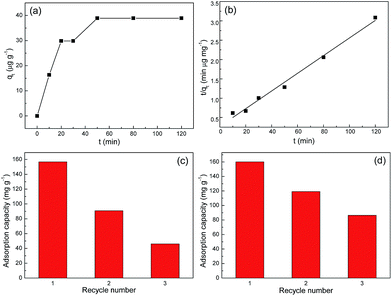 |
| | Fig. 8 (a) The kinetics of Cr(VI) adsorption onto S1 with an initial concentration of 50 μg L−1 at 293 K. (b) A linear plot of the pseudo-second-order model. Recycling of Cr(VI) adsorption on Fe3O4@C adsorbents: (c) S1 and (d) S2. The initial concentration of Cr(VI) is 300 mg L−1. | |
3.3 Desorption and regeneration studies
The regeneration of adsorbent is the most important aspect of an economical technology. In order to estimate the reusability of Fe3O4@C architectures, desorption of Cr(VI) from Fe3O4@C architectures were investigated. The 0.1 mol L−1 NaOH was used for desorption of Cr(VI). And the repeated adsorption of Cr(VI) was tested through 3 cycles of the adsorption/regeneration process. It is obviously seen from Fig. 8 that the first three cycles remain more than 50% adsorption capacity of Fe3O4@C architectures. This relatively low regeneration rate indicates the presence of tough valent bonds between Cr(VI) ions and the adsorbents. That is, the desorption agent NaOH is not quite efficient and effective to desorb Cr(VI) ions from Fe3O4@C adsorbents. This point can be demonstrated by the pH-dependent adsorption performance in Fig. 7a, in which the adsorption capacity values did not change significantly in the pH range of 3–11.
4. Conclusions
In summary, two types of Fe3O4@C nanosheets were fabricated by a facile template-assisted thermal treatment. The Fe3O4 NPs were found to orderly or unevenly distribute in the carbon sheets. The type and quality of template have critical impact on the morphology and arrangement of Fe3O4 NPs. On the basis of kinetics and equilibrium studies on the adsorptive removal of Cr(VI) from wastewater, the adsorption mechanism of Cr(VI) onto Fe3O4@C architectures is taken as a blend of physical and chemical adsorption processes. The high Cr(VI) adsorption capacities around 1100 mg g−1 above 308 K and easy magnetic separation from water are highly promising for their widespread potential applications in water treatment.
Acknowledgements
The authors are grateful to the financial aid from the National Natural Science Foundation of China (NSFC No. 51472133).
Notes and references
- C. J. Li, J. Ma, J. M. Shen and P. Wang, J. Hazard. Mater., 2009, 166, 891–896 CrossRef CAS PubMed.
- C. Y. Cao, J. Qu, F. Wei, H. Song and W. G. Liu, ACS Appl. Mater. Interfaces, 2012, 4(8), 4283–4287 CAS.
- K. Vijayaraghavan, D. Ahmad and R. Lesa, Ind. Eng. Chem. Res., 2006, 45(20), 6854–6859 CrossRef CAS.
- M. H. Li, Ind. Eng. Chem. Res., 2010, 49(4), 1822–1831 CrossRef CAS.
- C. Y. Cao, W. Guo, Z. M. Cui, W. G. Song and W. Cai, J. Mater. Chem., 2011, 21, 3204–3209 RSC.
- W. Z. Liu, F. Huang, Y. J. Wang, T. Zou, J. S. Zheng and Z. Lin, Environ. Sci. Technol., 2011, 45(5), 1955–1961 CrossRef CAS PubMed.
- Z. X. Wu and D. Y. Zhao, Chem. Commun., 2011, 47(12), 3332–3338 RSC.
- D. H. Chen, L. Cao, F. Z. Huang, P. Imperia, Y. B. Cheng and R. A. Caruso, J. Am. Chem. Soc., 2010, 132(12), 4438–4444 CrossRef CAS PubMed.
- X. Y. Yu, T. Luo, Y. X. Zhang, Y. Jia, B. J. Zhu, X. C. Fu, J. H. Liu and X. J. Huang, ACS Appl. Mater. Interfaces, 2011, 3, 2585–2593 CAS.
- X. Y. Yu, R. X. Xu, C. Gao, T. Luo, Y. Jia, J. H. Liu and X. J. Huang, ACS Appl. Mater. Interfaces, 2012, 4(4), 1954–1962 CAS.
- C. J. Madadrang, H. Y. Kim, G. Gao, N. Wang, J. Zhu, H. Feng, M. Gorring, M. L. Kasner and S. Hou, ACS Appl. Mater. Interfaces, 2012, 4, 1186–1193 CAS.
- K. Sasaki, N. Fukumoto, S. Moriyama and T. Hirajima, J. Hazard. Mater., 2011, 191, 240–248 CrossRef CAS PubMed.
- L. C. Zhou, Y. M. Shao, J. R. Liu, Z. F. Ye, H. Zhang, J. J. Ma, Y. Jia, W. J. Gao and Y. F. Li, ACS Appl. Mater. Interfaces, 2014, 6, 7275–7285 CAS.
- X. F. Zhang, J. Wang, R. Li, Q. H. Dai, R. Gao, Q. Liu and M. L. Zhang, Ind. Eng. Chem. Res., 2013, 52, 10152–10159 CrossRef CAS.
- X. L. Yao, S. B. Deng, R. Wu, S. Q. Hong, B. Wang, J. Huang, Y. J. Wang and G. Yu, RSC Adv., 2016, 6, 8797 RSC.
- Y. Lu and J. D. Miller, J. Colloid Interface Sci., 2002, 256(1), 41–52 CrossRef CAS.
- L. M. Bronstein, X. Huang, J. Retrum, A. Schmucker, M. Pink, B. D. Stein and B. Dragnea, Chem. Mater., 2007, 19(15), 3624–3632 CrossRef CAS.
- L. S. Zhong, J. S. Hu, H. P. Liang, A. M. Cao, W. G. Song and L. J. Wan, Adv. Mater., 2008, 20(15), 2977–2982 CrossRef.
- Y. Yuan, G. H. Zhang, Y. Li, G. L. Zhang, F. B. Zhang and X. B. Fan, Polym. Chem., 2013, 4, 2164–2167 RSC.
- H. Jabeen, V. Chandra, S. Jung, J. W. Lee, K. S. Kim and S. B. Kim, Nanoscale, 2011, 3, 3583–3585 RSC.
- Y. Wang, J. Ma and K. Z. Chen, Phys. Chem. Chem. Phys., 2013, 15, 19415–19421 RSC.
- J. Ma, Y. G. Wang, W. Liu, Y. H. He, Q. L. Sun, S. Z. Zuo-Jiang and K. Z. Chen, CrystEngComm, 2015, 17, 6699–6706 RSC.
- Y. Wu, H. J. Luo, H. Wang, C. Wang, J. Zhang and Z. Zhang, J. Colloid Interface Sci., 2013, 394, 183–191 CrossRef CAS PubMed.
- L. L. Li, L. L. Fan, M. Sun, H. M. Qiu, X. J. Li, H. M. Duan and C. N. Luo, Colloids Surf., B, 2013, 107, 76–83 CrossRef CAS PubMed.
- R. C. Wu, J. H. Qu and Y. S. Chen, Water Res., 2005, 39, 630–638 CrossRef CAS PubMed.
- A. El-Hamouz, H. S. Hilal, N. Nassar and Z. Mardawi, J. Environ. Manage., 2007, 84, 83–92 CrossRef CAS PubMed.
- N. N. Nassar, Can. J. Chem. Eng., 2012, 90(5), 1231–1238 CrossRef CAS.
- H. Tamura, A. Tanaka, K. Mita and R. Furuichi, J. Colloid Interface Sci., 1999, 209, 225–231 CrossRef CAS PubMed.
- H. Y. Shen, J. L. Chen, H. F. Dai, L. B. Wang and M. Q. Hu, Ind. Eng. Chem. Res., 2013, 52, 12723–12732 CrossRef CAS.
- Y. G. Zhao, H. Y. Shen, S. D. Pan and M. Q. Hu, J. Hazard. Mater., 2010, 182, 295–302 CrossRef CAS PubMed.
- Y. G. Zhao, H. Y. Shen, S. D. Pan, M. Q. Hu and Q. H. Xia, J. Mater. Sci., 2010, 45, 5291–5301 CrossRef CAS.
|
| This journal is © The Royal Society of Chemistry 2016 |
Click here to see how this site uses Cookies. View our privacy policy here.