Facile synthesis of ultrasmall stannic oxide nanoparticles as anode materials with superior cyclability and rate capability for lithium-ion batteries

Rong Li, Bingbing Wang*, Shidong Ji and Ping Jin*
Research Center for Industrial Ceramics, Shanghai Institute of Ceramics, Chinese Academy of Sciences, Dingxi 1295, Changning, Shanghai 200050, China

Received 12th January 2016 , Accepted 27th May 2016

First published on 31st May 2016


Abstract

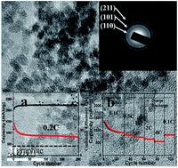
Ultrasmall monodisperse stannic oxide (SnO2) nanocrystals (diameter around 4 nm) with high-performance lithium storage are successfully synthesized via a simple calcination process, during which SiO2 mesoporous nanotubes (SiO2-MNT) are used to play an important role in restraining the growth and aggregation of the nanocrystals. As a kind of anode material for lithium-ion batteries, the as-prepared SnO2 nanocrystals show an excellent electrical performance with a super high reversible capacity of 816 mA h g−1 over 200 charge/discharge cycles at a current density of 160 mA g−1. Moreover, when the current density rises to 3200 mA g−1, the capacity is still as high as 550 mA h g−1, and it can be recovered to 816 mA h g−1 simultaneously when the current density turns back to 80 mA g−1. These results suggest that the obtained SnO2 nanocrystals can achieve a completely reversible transformation from Li4.4Sn to SnO during discharging (i.e., Li is extracted by dealloying and a reversible conversion reaction, generating 6.4 electrons). The superior electrochemical performance can be ascribed to the ultrafine particle size of SnO2, which promotes the reactive activity and alleviates the volume change of the anode composite during charge/discharge cycling.

1. Introduction

Lithium-ion batteries (LIBs) have been widely utilized in portable electronics and have shown significant promise in hybrid electric vehicles (HEVs), electric vehicles (EVs), and smart grids.1 Among numerous new candidates for anode materials, SnO2-based nanomaterials have attracted considerable attention as a potential substitute for graphite because of their plentiful appealing features, including low cost, abundance, environmental benignity, high theoretical capacity (783 mA h g−1), which is about twice that of graphite (theoretically 372 mA h g−1), and safe working potential (a few hundred millivolts higher than Li+/Li).2,3 Thus, a great deal of effort has been made in studying the electrochemical performance of the unique material. It is well established that two-step reactions are involved in SnO2-based electrodes:
 
SnO2 + 4Li+ + 4e → Sn + 2Li2O (1)
 
Sn + xLi+ + xe ↔ LixSn (0 ≤ x ≤ 4.4) (2)

In the first step (eqn (1)), SnO2 is reduced to nanometer-sized metallic Sn particles through an electrochemical conversion reaction which is widely believed to be irreversible. Subsequently, the newly formed Sn particles electrochemically react with Li to form LixSn alloy, which is a reversible process (eqn (2)). If only the alloying reaction is taken into account, according to eqn (2), the theoretical capacity would be 783 mA h g−1 based on 4.4 electrons (e−1) being involved in the redox reaction. However, SnO2-based anodes suffer from severe capacity fading caused by the large volume change (>300%), serious aggregation of tin particles which is formed during lithium insertion and continual formation of a very thick solid electrolyte interphase (SEI) during charge/discharge cycling which leads to pulverization of the electrodes and formation of electrochemically inactive substance Li2O as well as continual depletion of the electrolyte.2,3 Therefore, it is highly necessary to improve the capacity of SnO2 by rational designs, such as preparing nanostructured SnO2 with different morphologies, including nanoparticles,4 nanorods,5,6 nanowires,7,8 nanobelts,9 nanotubes,10–12 hollow spheres,13 and mesoporous structures,14 and fabricating SnO2 composites with other materials.15 These nanostructured SnO2 have been proven to exhibit a better electrochemical performance, especially ultrasmall nanoparticles.15,18 Nevertheless, it is such a great challenge to prepare SnO2 nanocrystals with a size less than 10 nm and few examples have been reported.16–18

Recently, several approaches such as utilizing supramolecular template have been reported for the preparation of SnO2 nanoparticles.29,30 In these methods, upon the removal of the surfactant, the SnO2 nanoparticles agglomerate and grow up leading to a poor electrochemical performance. In this work, we successfully synthesize ultrasmall monodispersed SnO2 nanocrystals with a high-performance lithium storage via a simple calcination process without any surfactants. In order to obtain monodispersed SnO2 nanocrystals, SiO2-MNTs are used as templates and also can inhibite the growth and aggregation of SnO2 nanocrystals. The as-obtained monodispersed SnO2 nanocrystals can deliver lower absolute volume change of the anode composite during cycling because of its ultrasmall size. In addition, the ultrafine nanostructure effectively maintain a morphological stability for the Li-ion insertion/extraction, which greatly increase electrochemical reactivity of the electrode/electrolyte, and successfully shorten the transport length for Li ions and electrons comparing to bulk materials.

2. Experimental

2.1 Preparation of SiO2-MNT

The synthesis method of SiO2-MNT was shown as follows:31 firstly, 0.2 mL of NaCl–glycerol solution (1.6 M) was injected into 20 mL isopropanol solution at 25 °C. Then 0.5 mL tetraethyl orthosilicate (TEOS, AR), 0.3 mL NH3·H2O and 1.0 mL deionized water were added into the mixture solution in twice. After reacting for 6 h, the mixture was centrifugated and collected. The SiO2-MNTs (Fig. S1) were obtained after washed with water and dried overnight under ambient conditions at 80 °C.

2.2 Preparation of ultrasmall SnO2 nanoparticles

The synthesis procedure for ultrasmall monodispersed SnO2 nanoparticles was shown as follows: 1 g SnCl4·5H2O (AR) was mixed with 1.2 g as-prepared SiO2-MNT in 50 mL deionized water and magnetic stired at 25 °C for 4 h, and then the mixture was centrifugated and dried under ambient conditions. Then, the precipitate was calcined at 550 °C for 4 h under ambient conditions. The SiO2-MNT templates were removed after treated with 1 M NaOH solution at 50 °C for about 1 day and washed with distilled water for several times. Finally, the ultrasmall monodispersed SnO2 nanoparticles were obtained and dried at 80 °C overnight.

2.3 Material characterizations

The microscopic morphology was obtained by field-emission scanning electron microscope (FE-SEM, HITACHI S-3400, Japan) at an acceleration voltage of 15 kV. The microstructure and composition of the samples were further analyzed by transmission electron microscope (TEM, JEOL 2010) with an energy dispersive spectrometer (EDS) attachment. The powder X-ray diffraction (XRD) patterns were recorded by Rigaku UItima IV diffractometer with Cu Kα X-ray radiation (λ = 1.5405 Å), using a voltage and current of 40 kV and 40 mA, respectively, with a scanning rate of 5° min−1. N2 adsorption/desorption measurements were performed by Micromeritics ASAP 2010. The pore size distribution was calculated from the adsorption branch of the sorption isotherms by Brunauer–Joyner–Halenda (BJH) method.

2.4 Electrochemical measurement

To examine the electrochemical performance, the working electrode was prepared by mixing the active materials, carbon black, and binder (polyvinylidene fluoride, PVDF) at a weight ratio of 80[thin space (1/6-em)]:[thin space (1/6-em)]10[thin space (1/6-em)]:[thin space (1/6-em)]10 in N-methyl pyrrolidinone (NMP). The slurry was deposited uniformly onto a copper foil with a diameter of 14 mm and dried in vacuum at 100 °C for 12 h, and the foil was tailored to an appropriate size by a coin-type cell microtome. Standard cells (CR 2025) with the above tailored foils as working electrode, lithium foils as reference and counter electrodes, polypropylene micro membrane as separator, the electrolyte, were assembled in an argonlled glovebox (Lab 2000). The electrolyte was made by dissolving 1 M LiPF6 into a mixture of ethylene carbonate (EC) and diethylene carbonate (DEC) at a volume ratio of 1[thin space (1/6-em)]:[thin space (1/6-em)]1. Cyclic voltammograms of the composite electrodes were scanned at 0.1 mV s−1 in a voltage window of 0.01–2.5 V. For cycling and rate performance, the electrodes were galvanostatically charged and discharged in a voltage cutoff of 0.01–2 V at various rates. 1C is defined as 800 mA g−1 (or 0.32 mA cm−2) for easy denotation.

3. Results and discussion

In this work, the formation of ultrasmall monodispersed SnO2 nanocrystals should correlate with the using of SiO2-MNTs which played a key role in restricting the nucleation and growth of the nanoparticles.20 In details, SnO2 precursors were deposited onto the surface of SiO2-MNTs by mixing SiO2-MNTs with SnCl4·5H2O in deionized water (the product of this step was denoted as H2SnO3/SiO2-MNT).12 This method could lead to the deposition of ultrasmall-sized particles of H2SnO3 onto the SiO2-MNT due to the slowly hydrolysis of SnCl4·5H2O. After heating the mixture at 550 °C for 4 h, these ultrasmall precursors transformed to SnO2 (the product of this step was denoted as SnO2/SiO2-MNT). Interestingly, high temperature calcination did not cause aggregation of these nanoparticles (Fig. S2a), indicating that mass diffusion of SnO2 was greatly restricted during heat treating. It revealed that SnO2 nanocrystals were anchored strongly on the surface of SiO2-MNT.

To explore the effect of SiO2-MNT, we performed a contrast experiment. SiO2 nanospheres were used to be the contrast templates, the SnO2 particles absorbed on SiO2 nanospheres under the same synthetic conditions (denoted as SnO2/SiO2-NS, Fig. S3), the SiO2 nanospheres were not mesoporous, and the size of the obtained SnO2 nanoparticles (Fig. S4) increased to about 10 nm. This can be ascribed to the mass diffusion of SnO2 without any restriction, which confirmed that the SiO2-MNT played an important role in inhibiting the growth and aggregation of such nanocrystals.

Fig. 1 shows XRD patterns of the as-prepared ultrasmall monodispersed SnO2 nanocrystals after (Fig. 1a) and before calcination (Fig. 1b). The diffraction peaks correspond well with the standard phase of tetragonal SnO2 (JCPDS no. 41-1445).18 Meanwhile, no impurity phases are observed. After high temperature calcination, the size of SnO2 particles increased from about 3 nm to 4 nm according to the Scherrer formula based on the 110 peak.18,21


image file: c6ra00964f-f1.tif
Fig. 1 XRD pattern of the SnO2 ultrasmall nanocrystals after (a) and before (b) calcination at 550 °C.

The morphology, particle size and crystal structure of ultrasmall monodispersed SnO2 nanocrystals were characterized by TEM and HRTEM (Fig. 2). As shown in Fig. 2a and b, SnO2 homogeneous nanocrystallites with an average diameter of 4 nm have been well dispersed without any aggregation. The selected area electron diffraction (SAED) pattern (Fig. 2c) exhibits three sharp diffraction rings, corresponding to the (110), (101), and (211) crystalline planes of rutile-type SnO2. In addition, the lattice fringes (Fig. 2d) of SnO2 nanocrystals clearly reveals a d-spacing of 0.33 nm, corresponding to the (110) plane of SnO2.19 Moreover, SnO2 nanocrystals with clear crystals fringes and diffraction rings are proven to be highly crystalline.19,22


image file: c6ra00964f-f2.tif
Fig. 2 TEM (a) and enlarged TEM (b) images of the as-synthesized ultrasmall SnO2 nanocrystals, the SADE pattern (c) and HRTEM image (d) of SnO2 ultrasmall nanocrystals.

Owing to its potential application in LIBs, it is necessary to evaluate the electrochemical performance of the as-obtained ultrasmall monodispersed SnO2 nanocrystals. Cyclic voltammetry (CV) was used to investigate the electrochemical process of the ultrasmall monodispersed SnO2 nanoparticles. Fig. 3a shows CV curves of the first three cycles of SnO2 electrode at a scan speed of 0.1 mV s−1 and cycled between 0.01 V and 2.5 V. It was found that there was a substantial difference between the first cycle and the subsequent cycles. In the first scanning cycle, the broad reduction peak around 0.86 V can be observed, which is attributed to the formation of the solid electrolyte interphase (SEI) and an amorphous lithium oxide (eqn (1)). Another prominent redox couple at 0.05 V and 0.61 V correspond to the reversible alloy–dealloy reaction (eqn (2)), which are the main contribution for lithium storage capacity.18 During the subsequent scanning cycles, the CV curves become stable, indicating that the reversible behavior can be some extent. The reduction peak shifts from around 0.86 V in the first cycle to 1.20 V in the subsequent cycles, which indicates that an irreversible reaction takes place only at the first cycle, corresponding to a large initial irreversible capacity loss.19 It should be noted that an obvious anodic peak at 1.20 V always appears at the first three oxidation cycles, suggesting the partial reversibility of eqn (1) and a multistep electron transfer from LixSn (0 ≤ x ≤ 4.4) to Sn and Sn to SnO or SnO2. Fig. 3b shows the charge–discharge behavior of SnO2 electrode in the potential window of 2–0.01 V in the 1st, 2nd, 10th, 50th, 100th cycles. It is obviously that two slope regions can be observed during the charge/discharge process. In accordance with the above CV peaks and previous reports18,23 each discharge curve can be divided into three stages: (1) the diffusion of the Li+ ions into the mesoporous structure; (2) the process of lithium insertion; (3) the insertion of lithium into the surface of material. We can also find that the discharge and charge capacities of the first cycle are 2560.8 and 1338.4 mA h g−1 respectively. The discharge capacity in the first cycle is larger than the theoretical capacity of SnO2 (783 mA h g−1). In general, the large irreversible loss in the first cycle can be ascribed to the formation of solid electrolyte interface (SEI) and the decomposition of SnO2 electrolyte.23


image file: c6ra00964f-f3.tif
Fig. 3 Cyclic voltammograms of the SnO2 ultrasmall nanocrystals at a scan speed of 0.1 mV s−1 within a voltage range of 0.01–2.5 V (a). (b–d) Electrochemical performance of the SnO2 ultrasmall nanocrystals anode cycled between 2.0 and 0.01 V. Charge/discharge voltage profiles for the SnO2 ultrasmall nanocrystals anode for the 1st, 2nd, 10th, 50th and 100th cycle at a current density of 0.16 A g−1 (b). Cycling performance of the SnO2-nanocrystal anodes, red for the ultrasmall monodispersed SnO2 (4 nm) and blue for the commercial SnO2 (c). The rate performance of the SnO2 ultrasmall nanocrystals anodes (d).

Fig. 3c displays the cycling performance of SnO2-nanocrystal electrode at 0.2C (160 mA g−1). We also compared the cycling performance of 4 nm (ultrasmall monodispersed), 10 nm, and commercial SnO2 (Fig. S5). Comparing to 10 nm and commercial SnO2, the capacity of ultrasmall monodispersed SnO2-nanocrystal electrode after 200 cycles is still as high as 817 mA h g−1, which is much higher than the theoretical capacity of SnO2 (783 mA h g−1) based on the stoichiometry of Li4.4Sn, while the capacity loss of the commercial SnO2 electrode is severe and the capacity of 10 nm SnO2 electrode is much lower than 4 nm SnO2's. The similar phenomenon is also observed in some other reports.20,23 The outstanding performance of ultrasmall monodispersed SnO2 can ascribe to its ultrasmall scale size which would shorten the Li+ ion diffusion and electron transport distance, ensure the efficient electrolyte penetration and increase the contact area between the electrode and electrolyte, provide good structural integrity of the electrode and prevent aggregation of primary nanoparticles. Meanwhile, the coulombic efficiency of SnO2-nanocrystal electrode after 10th cycle is maintained at around 100% (Fig. 3c), which is much more higher than that reported in other literatures.20,23 Moreover, we also studied the rate capability of SnO2-nanocrystal electrode. Fig. 3d shows the cyclic capacity retention of SnO2-nanocrystal electrode at different rates. It is clearly to see that the capacity decay of SnO2-nanocrystal electrode is relatively fast at lower current rates compared to that at higher current rates. When the current rates are 1C, 2C and 4C (800 mA g−1, 1600 mA g−1, 3200 mA g−1), the specific capacities for the 55th, 70th, and 85th cycle are 720 mA h g−1, 640 mA h g−1and 550 mA h g−1 respectively. After the current density returns to 0.1C, SnO2-nanocrystal electrode exhibits a higher capacity of about 816 mA h g−1. The high capacity and super stable circularity/cycling performance of the as-prepared SnO2 nanocrystals have seldom been reported previously. These data show that there is only an insignificant decrease in each rate for the SnO2-nanocrystal electrode. In addition, the result further implies that the lithium diffusion is highly efficient between the ultrasmall monodispersed nanocrystals, which provides more space to facilitate a fast scattering of Li+ ions.

In order to understand the superior electrochemical performance and the corresponding reaction mechanism in the as-prepared SnO2 nanocrystal, XPS and TEM were used to characterize the structural and morphological changes of the electrode. Fig. 4a shows the XPS spectrum for the Sn 3d levels for the SnO2-nanocrystal electrode. The Sn 3d5/2 peak is located at 487.1 eV and the Sn 3d3/2 peak is found at 495.5 eV, indicating the +4 valence state of the Sn. After 200th charge at 2 V (vs. Li/Li+), two obvious peaks at 486.7 and 495.1 eV are observed, which attribute to SnO. The XPS results clearly indicate that the matrix Li2O react with newly formed metallic Sn to form SnO when discharged to 2 V (vs. Li/Li+).15 The reversible conversion to SnO is also supported by the TEM image of the cycled SnO2-nanocrystal electrode. As shown in Fig. 4b, the overall morphology of ultrasmall monodispersed SnO nanoparticles is maintained. After 200 cycles, the ultrasmall SnO nanoparticles remain separated without any aggregation when discharged to 2 V (vs. Li/Li+), which contribute to the superior electrochemical performance of SnO2 nanocrystal anode materials. The corresponding SAED pattern (inset in Fig. 4b) confirms a crystalline SnO structure, indicating that Sn and Li2O could reversibly react to form SnO after the discharging process.18 This is in correspondence with the results of XPS. More importantly, the theoretical capacity of as-synthesized SnO2 anode materials is improved to 1273 mA h g−1 based on the above discussion. In addition, it also indicates that the ultrasmall monodispersed SnO2 nanocrystals with can not only suppress the volume change of the anode composite during cycling effectively, but also stabilize the electrode structure well. The volume stability is helpful to achieve high capacity retention and excellent cycling performance. Based on the above discussion, eqn (1) can be divided into the following equations:22,15

 
SnO2 + 2Li+ + 2e → SnO + Li2O (3)
 
SnO + 2Li+ + 2e ↔ Sn + Li2O (4)


image file: c6ra00964f-f4.tif
Fig. 4 XPS spectra for the Sn 3d levels at various depths of discharge state (pristine electrode (a), discharged to 2.0 V after 200 cycles (b)) (a), TEM image and the corresponding SAED image of the SnO ultrasmall nanocrystals after 200 cycles (b).

This deduction coincides well with the CV observation.

Recently, a range of transition metal oxides (Cu2O, CoO, FeO, etc.) have attracted much attention for their exceptional high capacity from the conversion reaction.24–26 The mechanistic study of such materials could provide lessons for high capacity electrode materials. However, only a very limited reversibility of the conversion reaction of SnO2 was observed in a few published studies.15 The reason for the irreversible conversion reaction in eqn (1) is the large volume change of SnO2 during lithiation/delithiation and the aggregation of metallic Sn particles from the decomposition of SnO2. In addition, much efforts have been made to modify SnO2 at the nanoscale, but with limited success.27,28 To date, there have been seldom reports of pure SnO2-based electrode materials with a substantial and stable reversible conversion reaction of SnO according to eqn (4) as we present in this paper.

4. Conclusions

In conclusion, ultrasmall monodispersed SnO2 nanocrystals with high-performance lithium storage have been successfully synthesized via a simple calcination process. Electrochemical experiments show that SnO2-nanocrystal electrode exhibits an excellent performance in capacity retention and rate capacity. The ultrasmall SnO2 nanocrystals deliver a high reversible capacity of 816 mA h g−1 over 200 charge/discharge cycles between 2 and 0.01 V at a rate of 160 mA g−1. A relatively high reversible capacity of 550 mA h g−1 also exists even at a rate of 3200 mA g−1, and it recovers to 816 mA h g−1 when the rate turns back to 80 mA g−1. The completely reversible transformation from Li4.4Sn to SnO during discharging benefit from the ultrasmall size of SnO2 nanoparticles. The superior electrochemical performance suggests that SnO2 nanocrystals are suitable for anode materials in high-performance LIBs. In addition, because the method is simple, direct, cost effective, and scalable, we hope it can be used to prepare other materials, especially electrochemical materials.

Acknowledgements

This study was financially supported by the Natural Science Foundation of China (NSFC, No. 51372264), and the Science and Technology Commission of Shanghai Municipality (STCSM, No. 13NM1402200, 14DZ2261203).

Notes and references

  1. R. Mahnke, J. Kaupuzs and I. Lubashevsky, Phys. Rep., 2005, 408, 1 CrossRef.
  2. R. Liu, D. Li, C. Wang, N. Li, Q. Li, X. Lü, J. S. Spendelow and G. Wu, Nano Energy, 2014, 6, 73 CrossRef CAS.
  3. J. Li, P. Wu, Y. Ye, H. Wang, Y. Zhou, Y. Tang and T. Lu, CrystEngComm, 2014, 16, 517 RSC.
  4. J. Venkateswarlu, R. L. Paddock, J. E. Raymond and D. J. Dan, J. Am. Chem. Soc., 2006, 128, 420 CrossRef PubMed.
  5. D. Zhang and C. Yan, Adv. Mater., 2003, 15, 1022 CrossRef CAS.
  6. B. Cheng, J. M. Russell, W. Shi, L. Zhang and E. T. J. Samulski, J. Am. Chem. Soc., 2004, 126, 5972 CrossRef CAS PubMed.
  7. Y. Wang, X. Jiang and Y. J. Xia, J. Am. Chem. Soc., 2003, 125, 16176 CrossRef CAS PubMed.
  8. Q. Kuang, C. Lao, Z. L. Wang, Z. Xie and L. J. Zheng, J. Am. Chem. Soc., 2007, 129, 6070 CrossRef CAS PubMed.
  9. j. Hu and Y. Bando, Adv. Funct. Mater., 2003, 13, 493 CrossRef CAS.
  10. J. Huang, N. Matsunaga, K. Shimanoe, N. Yamazoe and T. Kunitake, Chem. Mater., 2005, 17, 3513 CrossRef CAS.
  11. X. Zhang, J. Liang, G. Gao, S. Ding, Z. Yang, W. Yu and B. Q. Li, Electrochim. Acta, 2013, 98, 263 CrossRef CAS.
  12. J. Ye, H. Zhang, R. Yang, X. Li and L. Qi, Small, 2010, 6, 296 CrossRef CAS PubMed.
  13. X. W. Lou, Y. Wang, C. Yuan, J. Y. Lee and L. A. Archer, Adv. Mater., 2006, 18, 2325 CrossRef CAS.
  14. J. Ba, J. Polleux, M. Antonietti and M. Niederberger, Adv. Mater., 2005, 17, 2509 CrossRef CAS.
  15. M. He, L. Yuan, X. Hu, W. Zhang, J. Shu and Y. Huang, Nanoscale, 2013, 5, 3298 RSC.
  16. Y. J. Kim, Y. S. Kim, S. Y. Chai, D. H. Cha, Y. S. Choi and W. I. Lee, New J. Chem., 2007, 31, 260 RSC.
  17. Y.-H. Jin, K.-M. Min, S.-D. Seo, H.-W. Shim and D.-W. Kim, J. Phys. Chem. C, 2011, 115, 22062 CAS.
  18. Y. Chen, J. Ma, Q. Li and T. Wang, Nanoscale, 2013, 5, 3262 RSC.
  19. Z. Li, Q. Zhao, W. Fan and J. Zhan, Nanoscale, 2011, 3, 1646 RSC.
  20. H. Kim and J. J. Cho, Mater. Chem., 2008, 18, 771 RSC.
  21. B. Mallesham, P. Sudarsanam and G. Raju, Green Chem., 2013, 15, 478 RSC.
  22. X. W. Lou, C. M. Li and L. A. Archer, Adv. Mater., 2009, 21, 2536 CrossRef CAS.
  23. Y. Chen, J. Ma, L. Yu, Q. Li and T. Wang, CrystEngComm, 2012, 14, 6170 RSC.
  24. Z. Chen, M. Zhou, Y. Cao, X. Ai, H. Yang and J. Liu, Adv. Energy Mater., 2012, 2, 95 CrossRef CAS.
  25. J. Cabana, L. Monconduit, D. Larcher and M. R. Palacin, Adv. Mater., 2010, 22, E170 CrossRef CAS PubMed.
  26. T. Li, X. P. Ai and H. X. Yang, J. Phys. Chem. C, 2011, 115, 6167 CAS.
  27. Z. Chen, M. Zhou, Y. Cao, X. Ai, H. Yang and J. Liu, Adv. Energy Mater., 2012, 2, 95 CrossRef CAS.
  28. X. Zhou, L. J. Wan and Y. G. Guo, Adv. Mater., 2013, 25, 2152 CrossRef CAS PubMed.
  29. F. Chen and M. Liu, Chem. Commun., 1999, 1829 RSC.
  30. N. Ulagappan and C. N. R. Rao, Chem. Commun., 1996, 1685 RSC.
  31. J. T. Zhu, B. B. Wang and P. Jin, RSC Adv., 2015, 5, 92004 RSC.

Footnote

Electronic supplementary information (ESI) available. See DOI: 10.1039/c6ra00964f

This journal is © The Royal Society of Chemistry 2016
Click here to see how this site uses Cookies. View our privacy policy here.