Yuanzhu Long‡
,
Fuhua Sun‡,
Chao Liu and
Xingyi Xie*
College of Polymer Science and Engineering, Sichuan University, Chengdu, Sichuan 610065, China. E-mail: xiexingyi@263.net; xiexingyi@scu.edu.cn; 125682383@qq.com; 714562196@qq.com; 1172562559@qq.com; Fax: +86-28-85405402; Tel: +86-28-85405129
First published on 25th February 2016
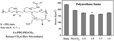
The polyurethane foam community has encountered increasing pressure to replace the ozone depleting and/or global warming blowing agents, such as chlorofluorocarbons (CFCs) and hydrochlorofluorocarbons (HCFCs). In this study, a series of polypropylene glycol-grafted polyethyleneimines (PPG-PEIs) were synthesised with the grafting rate ranging from 9% to 19%. Their CO2 adducts (PPG-PEI–CO2s) are thermally instable and can release CO2 to blow polyurethanes, whose polymerisation is exothermic. A PPG grafting rate of about 11% (found in sample 1:
9-PPG-PEI–CO2) is enough to homogenously disperse the blowing agent into polyurethane raw materials. The CO2 adducts with a PPG grafting rate of about 11–14% are particularly effective to decrease the foam density. The foams blown by 1
:
9-PPG-PEI–CO2 possess a thermal conductivity higher than those of traditional polyurethane foams (0.040 vs. 0.020–0.027 W m−1 K−1), hindering their application in thermal insulation. However, these new blowing agents are advantageous in zero emission of volatile organic compounds (VOCs), as well as their climate friendliness. We believe these blowing agents can be used in thermally insulating foams in cars and aircraft where VOCs are strictly regulated.
In response to the climate change concerns, volatile hydrocarbons like cyclopentane8 and certain unsaturated fluorinated compounds like 1-chloro-3,3,3-trifluoropropene (HCFO-1233zd)9–11 have been introduced due to their nearly zero ozone depletion potential and very low global warming potential; the latter value is reported as 7 for cyclopentane4 and 5 for HCFO-1233zd,11 in contrast to 950 for HFC-245fa (1,1,1,3,3-pentafluoropropane).7 We recently explored a hydrophobically modified polyethyleneimine which can reversibly absorb and release CO2 to blow polyurethanes.12 Poly(propylene glycol) (PPG) chains were grafted onto branched polyethyleneimine (bPEI) backbones, making the resulting PPG-PEI and its CO2 adduct compatible with PPG polyols which are widely used as raw materials for polyurethane foams. In addition to its climate harmony, this blowing agent releases no volatile organic compounds (VOCs) to atmosphere. This is important in applications like internal car insulation.
In this study, we further optimise the PPG grafting rate of PPG-PEI based blowing agents in order to improve blowing efficiency, while retaining enough raw material compatibility. We believe this optimisation is essential for the real application of this type of climate friendly blowing agents.
To synthesise the corresponding CO2 adduct, each PPG-PEI was spread on a piece of release paper and purged with a CO2 flow under mechanical stirring. The PPG-PEI quickly absorbed the CO2 and transformed into a white solid in about 1 min. The solid was ground into powder, put into a steel container and saturated with CO2 at 0.5 MPa for about 1 h. The resulting product was designated by adding “-CO2” after the corresponding 1:
x-PPG-PEI (x = 5, 7, 9, or 11, Fig. 1A), for example 1
:
11-PPG-PEI–CO2, 1
:
9-PPG-PEI–CO2, and so on.
Pure bPEI absorbs CO2 very slowly (the strong intermolecular H-bonding hindered the permeation of CO2 and such interaction could be reduced by PPG side chains in PPG-PEIs12). Therefore, its CO2 adduct was synthesised by saturation of 10% bPEI in ethanol with CO2 at 0.5 MPa for 2 d to form a white precipitate, followed by a complete ethanol evaporation at 40 °C for 5 d. This control sample was designated PEI–CO2.
Raw material | Description | Formulation (g) | |
---|---|---|---|
I | II | ||
a Polymeric 4,4′-diphenylmethane diisocyanate. | |||
White component | |||
Polyether 4110 | 4-Arm poly(propylene glycol), OH number 430 mg KOH g−1 | 8.50 | 8.50 |
Silicone L-3102 | Foam stabiliser | 0.16 | 0.26 |
Stannous octoate (T-9) | Catalyst | 0.02 | 0.02 |
Triethylenediamine (A-33) | Catalyst, 33 wt% in ethylene glycol | 0.20 | 0.04 |
Tris(1-chloro-2-propyl) phosphate (TCPP) | Diluent and plasticiser | 7.15 | 7.30 |
Propylene glycol | Chain extender | 0 | 0.06 |
Diethanol amine | Cross-linking agent | 0 | 0.20 |
1![]() ![]() |
Blowing agent, x = 5, 7, 9, or 11 | 0.50 (16.53) | 3.00 (19.38) |
![]() |
|||
Black component | |||
PMDIa | NCO content 31 wt% | 9.60 | 15.00 |
This set of experiments showed that 1:
9-PPG-PEI–CO2 was the most efficient blowing agent, resulting in the lowest foam density (about 160 kg m−3). The foaming art of 1
:
9-PPG-PEI–CO2 blown polyurethanes was further modified by ageing the thoroughly mixed white component at room temperature for 3 d. After ageing, PMDI was added to start the foaming process described in the previous paragraph.
To further lower the foam density, we conducted another set of experiments using an increased amount of blowing agents (3.00 g vs. 0.5 g) in the foam formulation (Formulation II, Table 1) while keeping the main ingredients like polyether 4110 and TCPP almost the same. Compared with Formulation I (Table 1), more foam stabiliser silicone L-3102 was used because much more bubbles would be generated in the new set of foams. The polymerisation speed was lowered using much less catalyst A-33, to possibly allow a full release of CO2 prior to foam solidification. Two new ingredients, propylene glycol and diethanol amine as the chain extender and cross-linker, respectively, could enhance the mechanical strength of the rising foams to reduce the breakage of growing bubbles. Moreover, they could assume more PMDI per unit mass than polyether 4110 because of their low molecular weights. Thus more PMDI was used in Formulation II. This would generate more heat, helping to release CO2 from the blowing agent. Except for the change in foam formulation, the foaming procedure was the same as described previously for the first set of foams. The whitening time, maximum foam-height time and tack-free time were also recorded.
Five replicates (n = 5) were used to test PU foam density and properties unless otherwise specified. The density was calculated based on the precise weight (±0.1 mg) and dimensions (±0.1 mm) of each sample. The compressive stress–strain curve was recorded on an Instron 5507 Universal Testing Machine at a strain rate of 15% per min (i.e. 3 mm min−1) according to ASTM D1621. The thermal conductivity was measured on a Hot Disk TPS 2500-OT thermal analyser. The dimensional stability was measured on cubic samples (about 27 cm3) after annealing at 100 °C and −20 °C for 96 h, respectively, according to ISO 2796. The water uptake was determined by the weight change before and after immersion into distilled water at 23 ± 2 °C for 96 h (ISO 2896), using cubic samples with a volume of about 125 cm3. The water vapour permeability was determined by standard method (GB/T 2411) as well.
Parameter | Original PEI | Feed molar ratio in 1![]() ![]() |
|||
---|---|---|---|---|---|
1![]() ![]() |
1![]() ![]() |
1![]() ![]() |
1![]() ![]() |
||
a From 1H NMR spectra, see ESI.b The calculation of these parameters is shown in ESI. The theoretical CO2 contents are calculated based on the fact that two amino groups or two repeating units capture one CO2 molecule. The normalised ΔH is calculated by excluding the mass of PPG side chains in each 1![]() ![]() |
|||||
Grafting rate y (%) | |||||
Theoretical (y = 1/x) | 9.1 | 11.1 | 14.3 | 20.0 | |
Measureda | 9.2 | 11.3 | 14.2 | 19.0 | |
PPG content (wt%)b | 46.0 | 50.9 | 56.7 | 63.6 | |
Mn (104 Da) | 2.42 | 4.30 | 4.62 | 5.19 | 5.87 |
Mw (104 Da) | 3.01 | 5.57 | 6.08 | 6.97 | 8.20 |
Mw/Mn | 1.25 | 1.30 | 1.32 | 1.34 | 1.40 |
![]() |
|||||
After conducted with CO2 | |||||
Theoretical CO2 content (%)b | 33.8 | 21.7 | 20.1 | 18.1 | 15.7 |
Measured weight loss (%) | 33.0 | 19.4 | 17.6 | 14.3 | 12.5 |
PPG content (wt%)b | 37.1 | 41.9 | 48.6 | 55.7 | |
Measured ΔH (J g−1) | 367 | 185 | 177 | 154 | 124 |
Normalised ΔH (J g−1)b | 294 | 305 | 300 | 280 |
The FTIR spectra of 1:
x-PPG-PEI also confirm their chemical structure (Fig. 2A). For instance, typical N–H bending from PEI and C–O–C stretching from PPG are identified at 1652 cm−1 and 1114 cm−1, respectively. The intensity of PPG methyl bending at 1375 cm−1 (* indicated, Fig. 2A) increased from 1
:
11- to 1
:
5-PPG-PEI, consistent with the increase of PPG content across these samples (Table 2).
The CO2 adducted samples displayed the same change trend in PPG methyl band (Fig. 2B). The CO2 adduction generated alkylammonium cations and carbamate anions (>NCOO− and –NHCOO−) (Fig. 1A) in the PEI backbones. This can be confirmed by a series of strong IR absorption bands at about 1630, 1570, 1477 and 1413 cm−1 (Fig. 2B), resulting from N–H bending in the alkylammoniums,13 CO stretching in the carbamates,13 the asymmetrical and symmetrical skeletal stretching of the carbamate anions,13–15 respectively. The changes in IR spectra before and after CO2 adduction agree with the results reported previously.12
Fig. 3 shows TG and DSC curves of the CO2 adducts. Negligible weight loss and zero enthalpy change (ΔH) were observed in the control sample 1:
5-PPG-PEI. The weight loss and endothermic process observed in the CO2 adducts can be associated with their CO2 release upon heating, as both showed the same temperature range for each sample (compare Fig. 3A and B). The measured weight loss in PEI–CO2 is very close to its theoretical CO2 content (33.0% vs. 33.8%, Table 2), showing complete CO2 absorption in this sample. Other samples possessed slightly lower weight loss than corresponding theoretical CO2 content (Table 2). Both measured weight loss and measured ΔH decreased from 1
:
11- to 1
:
5-PPG-PEI–CO2. However, the normalised ΔH's which excluded the weight of PPG side chains were similar across these samples (Table 2).
Among all CO2 adducts, PEI–CO2 displayed the widest temperature range of CO2 release spanning from 60 to 180 °C (Fig. 3B). Overall, PPG grafting decreased the upper limit of CO2 release range by about 30 °C. Sample 1:
9-PPG-PEI–CO2 demonstrated the lowest initial release temperature (at ∼70 °C) among the PPG-grafted samples.
![]() | ||
Fig. 4 Evolution of macroscopic and microscopic photographs of the white components (Formulation I, Table 1) with and without the CO2 adducts, after stirring at 400 rpm for 2 min. |
![]() | ||
Fig. 5 Property and morphology of polyurethane foams prepared with Formulation I (Table 1). ***: P < 0.001; **: P < 0.01; *: P < 0.05. (A) The foams blown by 1![]() ![]() ![]() ![]() |
Another set of foams was prepared based on Formulation II (Table 1). Since more blowing agent was used in this set of experiments (3.0 g vs. 0.5 g), the catalyst A-33 content was significantly lowered to decrease the polymerisation speed and to allow a possibly full release of CO2. This polymerisation slowdown was confirmed by the much longer whitening time, foam rising time and track-free time than those in the first set of experiments (Table 3). The blank sample displayed a much lower density than that in previous experiments (148.7 kg m−3 vs. 239.3 kg m−3, Table 4), showing more water present in the raw materials for this set of samples. Addition of the CO2 adducts significantly decreased the foam density and compressive strength as expected (Fig. 6 and Table 4). The density of CO2 adduct-blown samples varied narrowly between 59 and 74 kg cm−3. The 1:
9-PPG-PEI–CO2 blown foam possessed a similar density with PEI–CO2 and 1
:
7-PPG-PEI–CO2 blown samples (P > 0.05, Fig. 6A). However, its density was statistically lower than those of 1
:
11- and 1
:
5-PPG-PEI–CO2 blown foams.
Blowing agent | Whitening time (s) | Maximum foam-height time (s) | Tack-free time (s) | |||
---|---|---|---|---|---|---|
I | II | I | II | I | II | |
a Without blowing agent used. | ||||||
Blanka | 26 | 60 | 90 | 259 | 105 | 495 |
PEI–CO2 | 18 | 44 | 78 | 195 | 94 | 325 |
1![]() ![]() |
19 | 48 | 80 | 212 | 95 | 354 |
1![]() ![]() |
22 | 51 | 82 | 230 | 97 | 422 |
1![]() ![]() |
23 | 53 | 85 | 264 | 98 | 485 |
1![]() ![]() |
25 | 55 | 85 | 279 | 100 | 504 |
Blowing agenta | Density (kg m−3) | Foam volume (cm3) | Entrapped CO2b (ml) | Theoretically released CO2c (ml) | Foaming efficiencyd (%) |
---|---|---|---|---|---|
a No blowing agent was used in blank samples.b Calculated by subtracting blank foam volume from each foam volume.c Calculated based on the moles of CO2 (CO2 content from TG curve) in each blowing agent, the highest temperature of foaming process (about 110 °C and 100 °C for Formulation I and II, respectively) and the standard air pressure (P = 101![]() |
|||||
0.5 g, Formulation I | |||||
Blank | 239.3 ± 2.9 | 109.19 | 0 | ||
PEI–CO2 | 194.6 ± 2.2 | 134.28 | 25.09 | 117.90 | 21.3 |
1![]() ![]() |
174.5 ± 1.9 | 149.74 | 40.55 | 69.31 | 58.5 |
1![]() ![]() |
159.6 ± 2.2 | 163.72 | 54.53 | 62.88 | 86.7 |
1![]() ![]() |
165.0 ± 2.1 | 158.36 | 49.17 | 51.09 | 96.2 |
1![]() ![]() |
175.5 ± 2.6 | 148.89 | 39.70 | 44.66 | 88.9 |
![]() |
|||||
3.0 g, Formulation II | |||||
Blank | 148.7 ± 3.1 | 231.20 | 0 | ||
PEI–CO2 | 59.5 ± 2.1 | 577.82 | 346.62 | 688.94 | 50.3 |
1![]() ![]() |
69.2 ± 3.3 | 496.82 | 265.62 | 405.02 | 65.6 |
1![]() ![]() |
62.4 ± 3.0 | 550.96 | 319.76 | 367.43 | 87.0 |
1![]() ![]() |
66.0 ± 2.8 | 520.91 | 289.71 | 298.54 | 97.0 |
1![]() ![]() |
73.3 ± 3.0 | 469.03 | 237.83 | 260.96 | 91.1 |
![]() | ||
Fig. 6 Density and compressive strength of polyurethane foams prepared with Formulation II (Table 1). The compression tests (measured with five samples) were conducted at the foam rise direction. ***: P < 0.001; **: P < 0.01. |
It is reasonable that the net increase in foam volume relative to the blank sample stands for the CO2 volume trapped within the corresponding foam. Similarly, the percentage of trapped CO2 relative to theoretically released CO2 from each CO2 adduct indicates the foaming efficiency. Shown in Table 4, PEI–CO2 and 1:
11-PPG-PEI–CO2 demonstrated relatively low foaming efficiencies (21–66%) while 1
:
9-, 1
:
7- and 1
:
5-PPG-PEI–CO2 possessed foaming efficiencies of about 87% or over.
Table 5 compares the properties of 1:
9-PPG-PEI–CO2 blown foams with those required for applications in thermal insulation. The foam properties should be further optimised for these applications; in particular, the thermal conductivity should be lowered.
Property | Measured | Required properties for thermal insulationa | |||
---|---|---|---|---|---|
Building walls | Refrigerators | Underground steel pipes | |||
a Obtained from Chinese standards GB/T 10800, GB/T 2081 and SY/T 0415, respectively.b The height is parallel to foam rise direction. The minus data indicate shrinkage, and the controlled dimensional changes are given as absolute values. | |||||
Density (kg m−3) | 62.4 ± 3.0 | ≥30 | 28–35 | 40–60 | |
Compressive strength (kPa) | 203 ± 16 | ≥100 | ≥100 | ≥100 | |
Thermal conductivity (W m−1 K−1) | 0.040 ± 0.002 | ≤0.027 | ≤0.022 | ≤0.03 | |
Dimensional changes (%)b | |||||
−20 °C for 96 h | Length | −0.96 ± 0.05 | ≤1 | ||
Width | −1.17 ± 0.02 | ||||
Height | 1.31 ± 0.13 | ||||
100 °C for 96 h | Length | −1.14 ± 0.05 | ≤5 | ≤1.5 | ≤3 |
Width | −3.71 ± 0.20 | ||||
Height | 2.11 ± 0.13 | ||||
Water uptake (v/v%) | 2.3 ± 0.1 | ≤5 | ≤3 | ||
Water vapour permeability (ng m−1 s−1 Pa−1) | 7.22 ± 1.24 | ≤6.5 |
The weight loss (Fig. 3) of CO2 adducts was an endothermic process caused by the decomposition of alkylammonium carbamates in the main chain that released CO2. The PPG grafting resulted in a decrease in primary amine-derived carbamate anions (–NHCOO−) in corresponding CO2 adduct because PPG grafting can preferentially consume primary amines in original PEI. The –NHCOO− groups decompose at higher temperatures than >NCOO− groups due to extra H-bonds among the former. Therefore, the decomposition temperature range of PEI–CO2 (with more –NHCOO− anions) extended up to 180 °C, about 30 °C higher than the upper limit of other CO2 adducts (Fig. 3). Accordingly, the normalised ΔHs in 1:
x-PPG-PEI–CO2 were lower than the measured ΔH in PEI–CO2 (Table 2).
The PPG side chains in 1:
x-PPG-PEI–CO2 tended to expose to the liquid portion of the white component that contains a similar PPG polyol (polyether 4110, Table 1), which drove the dispersion of the CO2 adducts (Fig. 4). Both macroscopic and microscopic observation showed that samples 1
:
9-, 1
:
7- and 1
:
5-PPG-PEI–CO2 are compatible with the liquid white component while 1
:
11-PPG-PEI–CO2 and PEI–CO2 are not dispersible. The grafting rate of about 11% in 1
:
9-PPG-PEI–CO2 (Table 2) is enough to generate a homogeneous foaming mixture for PU foams.
The slowdown in foaming speed allows a more complete release of CO2 before the foam solidification. This partially accounts for the rough increase in foaming efficiency from 1:
11- to 1
:
5-PPG-PEI–CO2 (Table 4). The highest upper limit of CO2 release temperatures in PEI–CO2 (Fig. 3) might have prevented it from completely releasing CO2 during the foaming process. The poorest dispersibility of this sample (Fig. 4) resulted in the most inhomogeneous release of CO2; those relatively large bubbles might have broken up before the foam was set. All of these factors led to the lowest foaming efficiency in PEI–CO2 despite its highest CO2 content. For 1
:
11-PPG-PEI–CO2, its poor dispersibility was also responsible for its low foaming efficiency. Samples 1
:
9-, 1
:
7- and 1
:
5-PPG-PEI–CO2 could more completely release CO2 during the foaming process because of their similarly low CO2 release temperatures (Fig. 3). Their relatively higher dispersibility (Fig. 4) and thus more homogenous release of CO2 would inhibit the formation of very large bubbles with high potential to break, facilitating the improved foaming efficiency, which was in the range from 86% to 97%.
The large decrease in foaming speed from Formulation I to Formulation II (Table 3) caused an obvious increase in foaming efficiency in both PEI–CO2 and 1:
11-PPG-PEI–CO2 (Table 4). On the other hand, samples 1
:
9-, 1
:
7- and 1
:
5-PPG-PEI–CO2 displayed a stable and high foaming efficiency, regardless of the change in foaming formulation. In this case, the foaming efficiencies of PEI–CO2 and 1
:
11-PPG-PEI–CO2 were still much lower than those of 1
:
9-, 1
:
7- and 1
:
5-PPG-PEI–CO2 (Table 4). Again, the insufficient and/or inhomogeneous release of CO2 still occurred in both PEI–CO2 and 1
:
11-PPG-PEI–CO2 foaming systems.
Overall, a homogeneous CO2 release resulting from the high dispersibility of the CO2 adduct and a match between the polymerisation speed and the CO2 release rate are key factors for a high foaming efficiency. This was the case for the 1:
7-PPG-PEI–CO2 foaming system, which displayed a foaming efficiency as high as 96–97% (Table 4). The slightly lower foaming efficiencies (87–91%) found in 1
:
9- and 1
:
5-PPG-PEI–CO2 can be improved by finely adjusting the foaming formulation, e.g. using more foam stabiliser to avoid bubble breakage before foam solidification.
The foam density depends on the CO2 content (Table 2) and the foaming efficiency (Table 4) of each blowing agent. The polyurethanes blown by 1:
9-PPG-PEI–CO2 were among the least dense foams (Fig. 5 and 6). Only PEI–CO2 and 1
:
7-PPG-PEI–CO2 blown polyurethanes based on Formulation II had similar density (P > 0.05, Fig. 6A and Table 4). Currently, both 1
:
7- and 1
:
5-PPG-PEI–CO2 are acceptable in terms of good dispersibility and high foaming efficiency. Taking into consideration the higher CO2 content and its potential to further improve the foaming efficiency, 1
:
9-PPG-PEI–CO2 can be the most promising candidate for real applications.
The compressive strength is generally related to the density (Fig. 5B and 6B). However, the white component ageing for 3 days promoted the dispersion of 1:
9-PPG-PEI–CO2, thereby lowering and homogenising the pore size of the resultant foams (Fig. 5D). This morphological change did not affect the foam density but improved the compressive strength (indicated by *, Fig. 5C). The anisotropic morphology with the major axes of the elliptical pores pointing to the foam rise direction (Fig. 5D) is due to the horizontal confinement of the foam expansion by the container wall. As a result, the compressive strengths at the foam rise direction were larger than across it, both before and after the white component ageing (Fig. 5C). These observations clearly confirm that not only the foam density but also the porous morphology affects the mechanical strength.
The dimensional change of the current foam is suitable for building wall insulation, but not acceptable for insulations of refrigerators and underground steel pipes (Table 5). The roughly higher shrinkage perpendicular to foam rise direction than expansion parallel to it suggests a reduced pressure in the individual foam pores resulting from a fast outward diffusion of CO2 and a slow inward diffusion of air.16 This diffusion mismatch has been reported by Tseng et al.17 in a 25 mm thick polyurethane foam blown by CO2 and CFC 11 (1:
1, by v/v) where CO2 completely diffused out in about 3 days, while the volume of air infiltrated for about 1 month (almost no diffusion of CFC 11 was observed in the same period). The anisotropic dimension change is related to the anisotropic mechanical strength (Fig. 5C) showing that the foams are more easily compressed horizontally (i.e. perpendicular to foam rise direction). The dimensional change can be reduced by ageing the foams for a longer time (e.g. for one month) and/or by improving the mechanical strength via optimisation in foaming art (e.g. ageing the white component to homogenise the pore size, Fig. 5C and D).
A major obstacle for application in thermal insulations is the relatively high current thermal conductivity (Table 5). According to previously proposed models,17–19 the thermal conductivity (K) of a foam material is calculated by:
K = Kg + 2Ksρf/3ρs + 16σT3/3(42.038ρf + 121.55) | (1) |
Eqn (1) shows that the thermal conductivity is density-dependent; the minimum value reaches 0.0358 W m−1 K−1 at about 33 kg m−3 for the air-equilibrated foams, decreasing by only 0.002 W m−1 K−1 compared with the calculated value at 62 kg m−3. Lowering density is not an effective way to decrease the thermal conductivity. The minimum value is even higher than the upper limit of the required thermal conductivities in standards (Table 5). Therefore, the current foam is not suitable for the applications listed in Table 5, just taking into account the thermal insulation property.
Traditional blowing agents (CFCs, HCFCs and HFCs) on the one hand possess very low thermal conductivity (e.g. HCFC 141b: 0.01 W m−1 K−1; CFC 11: 0.0082 W m−1 K−1)20 and on the other hand diffuse very slowly through polyurethane foams (the diffusion coefficients of CO2, N2 and O2 are two to three orders of magnitude higher than those of HCFCs and CFCs).21 Therefore, the out-diffusion of traditional blowing agents can last for years,22,23 helping to preserve the low thermal conductivity of the foams. For instance, a 1 cm-thick polyurethane foam blown by HCFC 141b still retains a thermal conductivity below 0.026 W m−1 K−1 after a 2 year ageing at 32.2 °C.22
The thermal conductivity (0.040 W m−1 K−1) of 1:
9-PPG-PEI–CO2 blown polyurethane foams is comparable to those of expanded polystyrene (0.029–0.041 W m−1 K−1), but higher than those of traditional polyurethane foams (0.020–0.027 W m−1 K−1).24 The benefits due to zero emission of climate changing substances in the new blowing agents and the benefits due to the higher thermal resistance in traditional blowing agents should be comprehensively compared in terms of climatic impact, for example using life cycle analysis,7,25 which considers all impacts during the manufacturing processes and the overall life cycle of the corresponding foam product.
The long-term release of blowing agents from traditional polyurethane foams can limit their application as thermal insulation materials in a closed or semi-closed environment (e.g. in cars, trains and aircrafts) where the local concentration of VOCs is strictly regulated.26,27 In this case, the new polyurethane foam in this study is a good alternative.
Footnotes |
† Electronic supplementary information (ESI) available: Details on characterization methods, calculations about grafting rate of PPG-PEIs, and calculations about the theoretical CO2 content of each CO2 adduct. See DOI: 10.1039/c6ra00422a |
‡ Both authors equally contributed to the paper. |
This journal is © The Royal Society of Chemistry 2016 |