
First principles calculations on the hydrogen atom passivation of TiO2 nanotubes†
Jianhong Dai and
Yan Song*
School of Materials Science and Engineering, Harbin Institute of Technology at Weihai, 2 West Wenhua Road, Weihai 264209, China. E-mail: sy@hitwh.edu.cn
First published on 4th February 2016
Abstract
First principles calculations are carried out to study the hydrogen atom passivation properties of TiO2 nanotubes. The influence of charge on the stabilities of the TiO2 nanotubes with or without hydrogen atom passivation is studied. Two types of anatase TiO2 nanotube, denoted as (m, 0) and (0, n) (m = 6, 9 and n = 3, 6), were considered in the present work. The formation energy of the charged systems and the adsorption energy of the hydrogen atoms are evaluated. The negatively charged (6, 0) nanotubes and one charge state containing (0, 3) nanotubes possess low formation energies, indicating that they are easy to form among the considered nanotubes. The electronic structures of the TiO2 nanotubes are analyzed using several methods. It was found that the adsorbed hydrogen atoms can easily donate electrons to the oxygen atoms of the TNTs. Furthermore, the charge and hydrogen atom passivation cause the diverse distribution of states around the Fermi energy level, and therefore, may expand the potential applications of TiO2 nanotubes.
1. Introduction
TiO2 has been widely applied as a white pigment, in sun-blockers, and has also attracted great attention as a semiconductor photocatalyst, and in gas sensors and solar cells.1,2 Due to their special radiation tolerance and specific surface area, TiO2 nanotubes (TNTs) show promising field-emission abilities and potential for biological coatings.3,4 One dimensional TNTs can be prepared by various routes,5,6 in which the self-organized nanotubes can be easily formed by electrochemical oxidation of titanium alloys.4 The highly-ordered TiO2 nanotube arrays show promising application in dye-sensitized solar cells and hydrogen production using water photoelectrolysis.7,8TNTs possess large specific surface areas and outstanding charge carrier transport abilities compared to bulk TiO2.9 They have high potential for application as novel reactors, photo-reactors and sensors for energy production. The electronic and optical properties of TiO2 nanostructures are strongly associated with their symmetry, dimensions and morphology.10 The electronic and transport properties of anatase TiO2 nanotube arrays are sensitive to the adsorption of O2, NO and NO2.11 The hydrogen can affect the photolysis properties of TiO2. The H atom prefers to adsorb on the top O site of the rutile TiO2(011)-2 × 1 surface and enhances the optical absorption of TiO2.12 Hydrogen molecules interact weakly with TiO2,13,14 but the hydrogen atom strongly interacts with TiO2.15,16 A TiO2 cluster induces an intensive interaction between H atoms and doped graphene.17 Therefore, TiO2 nanotubes possess excellent hydrogen sensing and photocatalytic properties.18 TNTs have shown great promise for gas sensing due to their large surface areas and high reactivities. The TNTs are sensitive to hydrogen.19–21 The high variation of electrical resistance in TNTs was observed under 100–500 ppm of a hydrogen environment.22 The TNT sensor shows a short response time and a high selectivity for H2 against several reducing gases.21 Doping can modify the band structure of TNTs, and will expand their applications as chemical sensors. Such as the gold nanoparticle supported TNTs which show a high sensitivity to O2 in aqueous solution.23 Lin et al. first compared the influence of the adsorption of hydrogen molecules and hydrogen atoms on TNTs. The hydrogen molecules had little effect on the electronic structure of the TNTs,24 and had small binding energies (0.05 eV per H2 molecule).11,25 The hydrogen atom prefers to bond with the two-fold-coordinated oxygen of the TNTs and donates its electron to the nanotube causing a semiconductor-to-metal transition.24 These calculations imply that there are strong bonding interactions between the hydrogen atom and the oxygen atoms of the TNTs. The influence of charge on the adsorption properties of atomic hydrogen on the TNTs is considered in the present work to explore the possible applications of TNTs under complex environments. The hydrogen passivation also affects the corrosion resistance of a titanium implant. The corrosion resistance properties of biomaterials are complex under human body conditions, in which the variations of ionic and protein composition and concentration that will affect the pH value of the implant’s surrounding environment should be considered. A wide range of pH values, (5.4–8.1),26 (5.5–7.0)27 and (2.0–9.0),28 should be considered when testing the corrosion resistance of titanium alloy. The elution of Ti ions from a Ti implant in the SBF is influenced by pH value.28
The photocatalytic properties of TNTs are closely related to their electronic structures. Suitable band gaps and band-edge states will improve their photocatalytic performance. Asahi et al. first suggested that anion dopants can reduce the band gap.29 The stability of charged oxygen vacancies in rutile TiO2 is found to be affected by the Fermi energy, the +2 charge state of the O vacancy is the most stable if EF is in the region of 0 to 2.8 eV, while the neutral vacancy is stabilized above 2.8 eV.30 A pentavalent dopant (Nb5+ or Ta5+) releases one extra electron into TiO2 introducing donor levels.31,32 The additional electron can be captured by the Ti atom (Ti4+) and reduces Ti4+ to Ti3+ resulting in insulating properties.33 Furthermore, adsorption of hydrogen affects the interactions between the nanomaterial and a protein, such as the bonding interactions between the side chain of an amino acid and the surface of a metal oxide. An acidic amino acid will form an orderly cover on the TiO2 surface, while a non-acidic amino acid hardly adheres on the TiO2 surface.34 The interactions between a protein and TiO2 are greatly affected by the charge distributions of the nanomaterial surface.35,36 Furthermore, acidic electrolytes, such as HF based electrolytes, are widely used during the fabrication of titania nanotubes.37,38 The pH value greatly affects the length of the nanotubes.39 Therefore, the stability of TiO2 nanotubes may be greatly affected by the adsorption of H ions. However, the influence mechanisms of charge and hydrogen atom passivation on the electronic structures of TiO2 nanotubes are still not addressed in detail.
In this work, the influence of the charge state and hydrogen atom passivation on the electronic structures of TNTs is studied via first principles calculations. The method used in this paper is briefly described in Section 2, and the results are presented in Section 3. Conclusions are summarized in the last part.
2. Methodology and models
For most anatase nanocrystals, the (101) surface is thermodynamically more stable than the reactive (001) facets,40 therefore anatase TiO2 nanotubes rolled by the (101) surface are studied in the present work. Although TNTs have been extensively studied, their configurations still remain unclear, especially the atomic structure of the nanotube wall.41 The O/Ti ratio of a nanotube varies with the morphology of the nanotubes.42 Simulations of TNTs are often based on the model devised by Wang et al., in which the nanotube is rolled from a 2D sheet.43 The roll-up direction determines the structure of the nanotube. The details about the structures of TNTs are reviewed by Hossain et al.41 In the present work, (0, n) and (m, 0) TNTs are selected. These two types of nanotube occur with great differences in their atomic structures, i.e., the depth of the unit tube, and especially the arrangement of the dangling bond of the nanotube. The oxygen atoms distribute in the bridge or in the layer site in (m, 0), while they align parallel to the axis in the (0, n) tubes. These two types of nanotube possess different stabilities and electronic structures,44 and therefore, they will possess different adsorption abilities for hydrogen atoms or other clusters. It is worth noting that the separated and connected nanotubes can be synthesized by controlling the preparation anodic oxidation. The arrangements of the nanotubes greatly affect their stability and electronic structure.10 The (0, n) and (m, 0) nanotubes can be constructed by rolling an anatase (101) sheet along the [101] and [010] directions, respectively.45 Fig. 1 shows the structural configurations of the (0, 3) and (6, 0) nanotubes. The simulated boxes of the (6, 0) and (0, 3) tubes are 30.0 × 30.0 × 10.210 Å3 and 30.0 × 30.0 × 3.776 Å3, respectively to ensure the tubes are separated by more than 15 Å of vacuum in order to avoid interactions between the tubes. The total energies and electronic structures of the nanotubes are evaluated via the Vienna ab initio simulation package (VASP).46,47 The PAW-GGA potential is used.48 The self-consistent convergence for the total energy difference is less than 10−5 eV and the forces acting on the ions dropped below 0.01 eV Å−1. The energy cutoff is 400 eV and 1 × 1 × 2 and 1 × 1 × 8 k-meshes were chosen for the (6, 0) and (0, 3) nanotubes, respectively. In order to check the influence of size on the stability and hydrogen atom passivation properties of the TiO2 nanotubes, the (9, 0) and (0, 6) nanotubes were constructed with the above approach. | ||
| Fig. 1 The configurations of the TiO2 nanotubes, the blue and red atomic spheres denote the Ti and oxygen atoms, respectively, (a) (6, 0) and (b) (0, 3). | ||
3. Results and discussion
3.1. Stability of the charged TNTs
For the charged systems, charge compensation was introduced using a homogeneous background-charge. The negatively and positively charged systems indicate the excess and absence of electrons compared to the neutral systems. After full relaxations, the diameters of the charged nanotubes are slightly changed, as shown in Fig. 2. For the (6, 0) tubes, both the positive and negative charge defects enlarge the diameter up to 0.05 Å, while for the (0, 3) tubes, the diameter of the tubes monotonically decreases from the −3 to +3 charge state, and its maximum absolute change is about 0.4 Å. | ||
| Fig. 2 The diameters of the charged TiO2 nanotubes. | ||
The stability of the charged systems is evaluated via the formation energy given by:
| ΔH(q) = Edefectq − Eperfect + q[EV + EF + ΔV] + δ | (1) |
| System | (6, 0) | (0, 3) | ||
|---|---|---|---|---|
| EF = VBM | EF = CBM | EF = VBM | EF = CBM | |
| p3 | 14.363 | 18.131 | 10.271 | 17.780 |
| p2 | 7.379 | 9.891 | 4.675 | 9.681 |
| p1 | 2.566 | 3.822 | 1.147 | 3.650 |
| n1 | 1.608 | 0.352 | 3.873 | 1.370 |
| n2 | 3.696 | 1.184 | 9.107 | 4.101 |
| n3 | 3.062 | −0.706 | 14.866 | 7.357 |
Due to the interactions between the charge defects, the energy corrections will become inaccurate for highly charged defects. However, there is not a universal method to deal with the charge defects, and therefore, we will focus on the qualitative comparison. For the charged systems, both positive and negative charge states denoted as px and nx are considered, in which the x indicates the charge state. For the (6, 0) nanotubes, the positively charged systems show a higher formation energy than the negatively charged systems. The p3 and p2 systems show significantly higher formation energies, indicating these charged systems are hardly stabilized. The negatively charged systems show relatively low formation energies when the Fermi energy is equal to the CBM. There is a negative formation energy for the n3 system if EF = CBM meaning there is thermodynamic stability. For the charged (0, 3) systems, the formation energies are all very high except for the p1 system when the Fermi energy equals the VBM, and the n1 system when the Fermi energy equals the CBM. Therefore, the p1 and n1 systems may be easier to form compared to the other charged (0, 3) systems.
3.2. Hydrogen atom passivation
The adsorption ability of the hydrogen atoms on the nanotubes is evaluated using the adsorption energy, Eads, defined as in the following:| Eads = (ENT+H − ENT − nEH)/n | (2) |
Table 2 lists the hydrogen atom adsorption energy in the TNTs. For the neutral systems, the hydrogen atom adsorption energy is smaller for the (0, 3) tubes than for the (6, 0) tubes. Generally, the ability of the TNTs for attracting hydrogen atoms is in the order of the positively charged, neutral, and negatively charged TNTs. The p3 and p2 values of the (0, 3) systems show negative hydrogen atom adsorption energies. It is interesting to note that the larger the value of positive charge contained in a system, the smaller hydrogen atom adsorption energy it possesses. Therefore, the adsorption of a hydrogen atom strongly depends on the charge state of the TNTs.
| System | p3 | p2 | p1 | Neutral | n1 | n2 | n3 |
|---|---|---|---|---|---|---|---|
| (6, 0) | 0.184 | 0.405 | 0.617 | 0.782 | 0.883 | 0.928 | 0.943 |
| (0, 3) | −0.662 | −0.223 | 0.212 | 0.615 | 0.776 | 0.815 | 0.846 |
| (9, 0) | 0.030 | 0.179 | 0.324 | 0.450 | 0.530 | 0.582 | 0.608 |
| (0, 6) | 0.012 | 0.231 | 0.444 | 0.631 | 0.752 | 0.832 | 0.885 |
It is worth noting that the adsorption energies of hydrogen atoms on the charged (0, 3) tubes are negative, which may be caused by the interactions between the hydrogen atoms or charges due to the small size of the nanotubes. In order to study the influence of the size of a tube on the adsorption of a hydrogen atom, the adsorption of a hydrogen atom on the (9, 0) and (0, 6) tubes was further studied. The size of the simulated cell for the (9, 0) and (0, 6) tubes is 30 × 30 × 10.210 Å3 and 30 × 30 × 3.776 Å3, respectively. The hydrogen atom adsorption energies are shown in Table 2. Similar hydrogen atom adsorption trends on these tubes were observed implying a weak dependence of the adsorption of hydrogen atoms on the size of the nanotubes, however, there are no negative adsorption energies for the (9, 0) and (0, 6) tubes. The positively charged nanotubes show smaller adsorption energies of hydrogen atoms than the adsorption energies of hydrogen atoms on the negatively charged tubes. Therefore, the adsorbed hydrogen atoms can easily donate electrons and make the surface of the TiO2 nanotubes positively charged, which will benefit the adsorption of a negative cluster, i.e., [PO4]3− or [OH]− on the nanotubes.
The fractional pseudopotentials of H, which enable the description of the fractional charge states of the H atoms, provided by VASP were further used to study the relationship between the stability of the nanotubes and the valence electrons of the H atoms. H pseudopotentials with 0.5, 0.75, 1.25, and 1.5 valence electrons were adopted in the present study. The adsorption energies of the hydrogen atoms with different valence states are shown in Table 3. Herein, the hydrogen atom energy in eqn (2) was regarded as the energy of a free hydrogen atom considering that the hydrogen atom with the different valence electrons is indeed in an atomic state. Due to the smaller value of the energy of the free atom than the corresponding molecule, the adsorption energies are all negative. Among these systems, one can find that the systems with valence states of 0.75 of the hydrogen atom have smaller adsorption energies. This means that the positively charged nanotubes have better hydrogen atom adsorption properties, which is consistent with the above calculation results.
| Valence | (9, 0) | (6, 0) | (0, 6) | (0, 3) |
|---|---|---|---|---|
| 0.5 | −2.437 | −2.248 | −2.332 | −2.367 |
| 0.75 | −3.042 | −2.754 | −2.887 | −2.932 |
| 1.0 | −2.841 | −2.500 | −2.659 | −2.666 |
| 1.25 | −1.845 | −1.732 | −1.325 | −1.416 |
| 1.5 | −1.986 | −2.108 | −2.030 | −2.006 |
3.3. Electronic structures
In order to compare the influence of the radius of the tubes on the charge distributions, the circle averaged distribution of charges (CAD) is calculated. The CAD is defined as the average charge in the concentric cylindrical surface within the tube. The differences in the CAD between the charged and the neutral systems are evaluated and shown in Fig. 3(a) and (b) for the (6, 0) and (0, 3) tubes, respectively. The horizontal line represents the CAD of the neutral TNTs. For the charged (6, 0) systems, the variations in the CAD differences for the positively and negatively charged systems are symmetrical according to the neutral system. The largest value of the CAD difference appears around 3.75 Å. Therefore, the influence of charge is mainly concentrated around the circle of 3.75 Å radius, which is about 0.05 Å away from the surface Ti atoms of the tubes. Compared with the (6, 0) systems, the distributions of CAD difference in the (0, 3) systems are more broad, and the largest values presented in the circle of 5.25 Å radius. Generally, the positively charged systems change more dramatically than the negatively charged systems. It is worth noting that the large charge defect causes large changes in the CAD difference, and therefore may cause a large formation energy for the corresponding systems. | ||
| Fig. 3 The distributions of CAD difference between the charged and neutral TiO2 nanotubes, (a) (6, 0) and (b) (0, 3). | ||
The charge difference distributions between the charged and neutral systems with the same geometric structures are studied. Results are shown in Fig. 4. For the (6, 0) systems, the distributions of charge are highly symmetrical, the oxygen and titanium atoms show similar distribution characteristics. The outer oxygen atoms show larger charge defects than the inner oxygen atoms. The (0, 3) systems also show similar characteristics to the (6, 0) systems. Therefore, the charges are symmetrically distributed in the nanotubes, and mainly affect the charge distributions around the oxygen atoms.
 | ||
| Fig. 4 The charge difference distributions of the charged TiO2 nanotubes, (a) (6, 0) and (b) (0, 3). | ||
The total and partial densities of states (TDOS, PDOSs) of the charged systems are shown in Fig. 5 and 6. Fig. 5 shows the DOSs of the charged (6, 0) systems. Generally, the charge alters the position of the Fermi energy level, but rarely affects the band gap. In the negatively charged systems, the extra electrons produce a shift of the DOSs to the low energy region and push the Fermi energy level toward the low energy region as well. While it shows the opposite characteristics in the positively charged systems. Bonding peaks are eventually moved toward the high energy region due the deficiency of electrons. It is worth noting that the band gap is mainly restricted by the O p electrons in the valence band and the Ti d electrons in the conduction band. There are four bonding peaks for the O p electrons in the valence band in the negatively charged systems and five bonding peaks for the O p electrons in the positively charged systems, respectively, meaning that the distribution of bonding peaks in the negatively charged systems is more concentrated than in the positively charged system. The distribution of Ti d orbitals also shows similar characteristics. Therefore, the negatively charged systems are more stable than the positively charged systems.
 | ||
| Fig. 5 The density of states of the charged (6, 0) TiO2 nanotubes, (a) total density of states, (b) and (c) are the partial density of states of the O and Ti atoms in the (6, 0) TiO2 nanotubes, respectively. | ||
 | ||
| Fig. 6 The density of states of the charged (0, 3) TiO2 nanotubes, (a) total density of states, (b) and (c) are the partial density of states of the O and Ti atoms in the (0, 3) TiO2 nanotubes, respectively. | ||
The DOSs of the charged (0, 3) systems are shown in Fig. 6. Contrasting with the charged (6, 0) systems, the positively charged systems show similar distributions to the perfect systems. While the bonding peaks of the negatively charged systems obviously shift toward the low energy region, caused by the extra electrons. The bonding peaks around the VBM are mainly contributed by the O atoms, while the CBM peaks are mainly contributed by the Ti atoms. Therefore, the band gap of the (0, 3) nanotubes is dependent on the distributions of occupation of the Ti d and O p orbitals, and the n1 and p1 systems possess smaller formation energies than those of the other charged systems. It is worth noting that the charge obviously causes the movement of the Fermi energy level. For the negatively charged systems, the Fermi energy level moves toward the conduction band, while it moves toward the valence band in the positively charged systems. These movements of the Fermi energy level both cause new states at the Fermi energy level, which will make the TNTs undergo a semiconductor-to-metal transition.
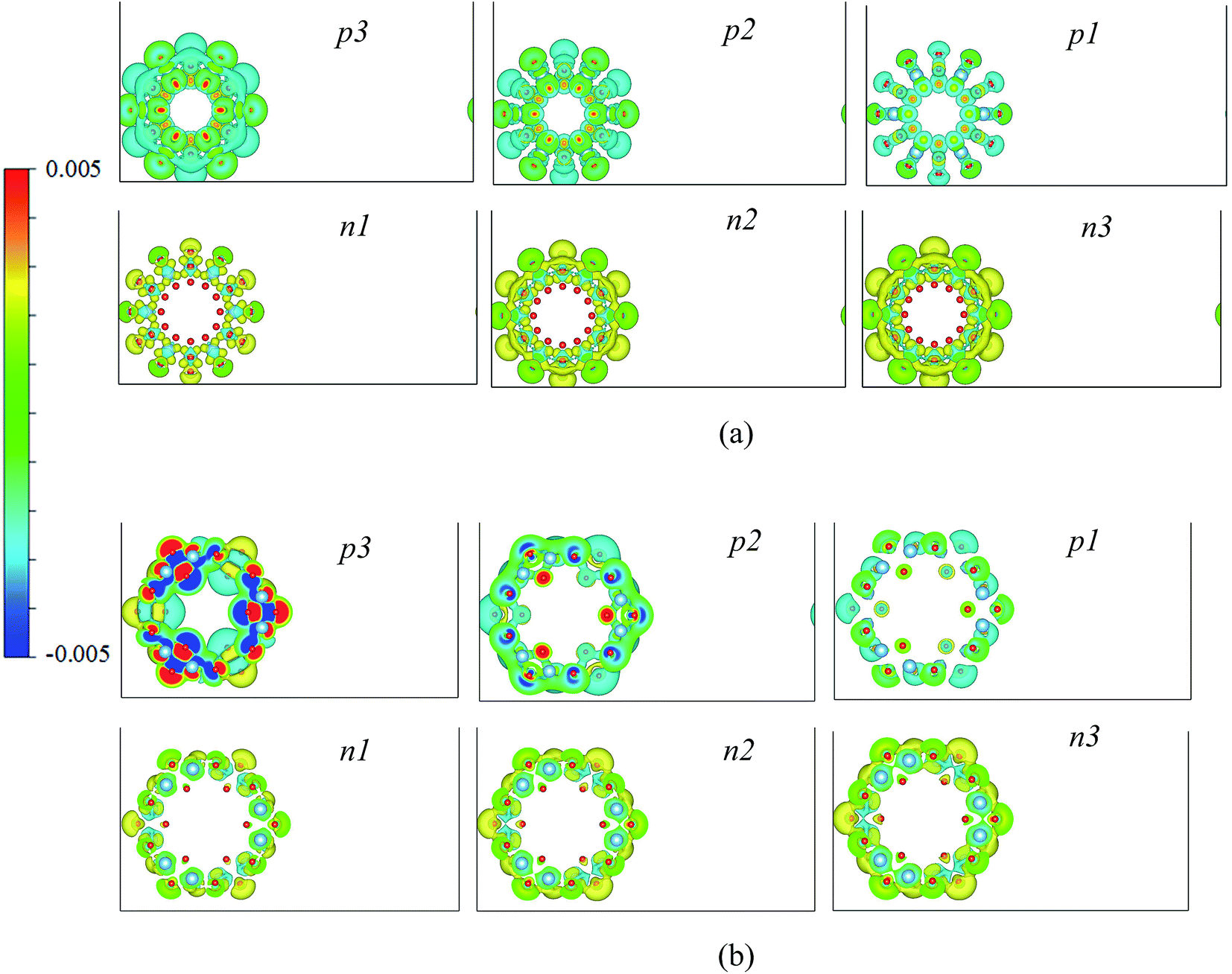
In order to study the influence mechanism of the charge on the adsorption of the hydrogen atoms, the electronic structures of the p3, neutral, and n3 systems of both (6, 0) and (0, 3) tubes are analyzed. The electron localization function (ELF)50,51 is calculated. The ELF is highly connected with the electron localization: ELF = 1 and 0 means perfect localization and no electrons, respectively. The distributions of the ELF of the charged systems are shown in Fig. 7 with a scale from 0.8 (red) to 0.0 (blue). The distributions of the ELF are highly symmetrical to the central point of the nanotubes. The red regions are distributed around the oxygen and hydrogen atoms, and the values of the ELF around the Ti atoms are similar to the vacuum region. This indicates that a certain amount of charge is transferred from the Ti to the O atoms forming an ionic bond between them and a covalent bond between the O and H atoms. Comparing the hydrogen atom passivated and the neutral nanotubes, there are obvious rich-charge regions in the central part of the hydrogen atom passivated nanotubes, and therefore, the charge distributions are changed by the adsorption of the hydrogen atoms. The distributions of charge in the central region of the nanotubes may bring new photoelectric functions. For the distributions of the ELF of the hydrogen atom passivated nanotubes, the negatively charged nanotubes show a higher value of ELF than the positively charged nanotubes. Furthermore, the negative charge increases the value of the ELF around the central axis, indicating that more charges are concentrated in the central zone of the nanotubes than the positively charged nanotubes.
 | ||
| Fig. 7 The distributions of the ELF of the charged TiO2 nanotubes. | ||
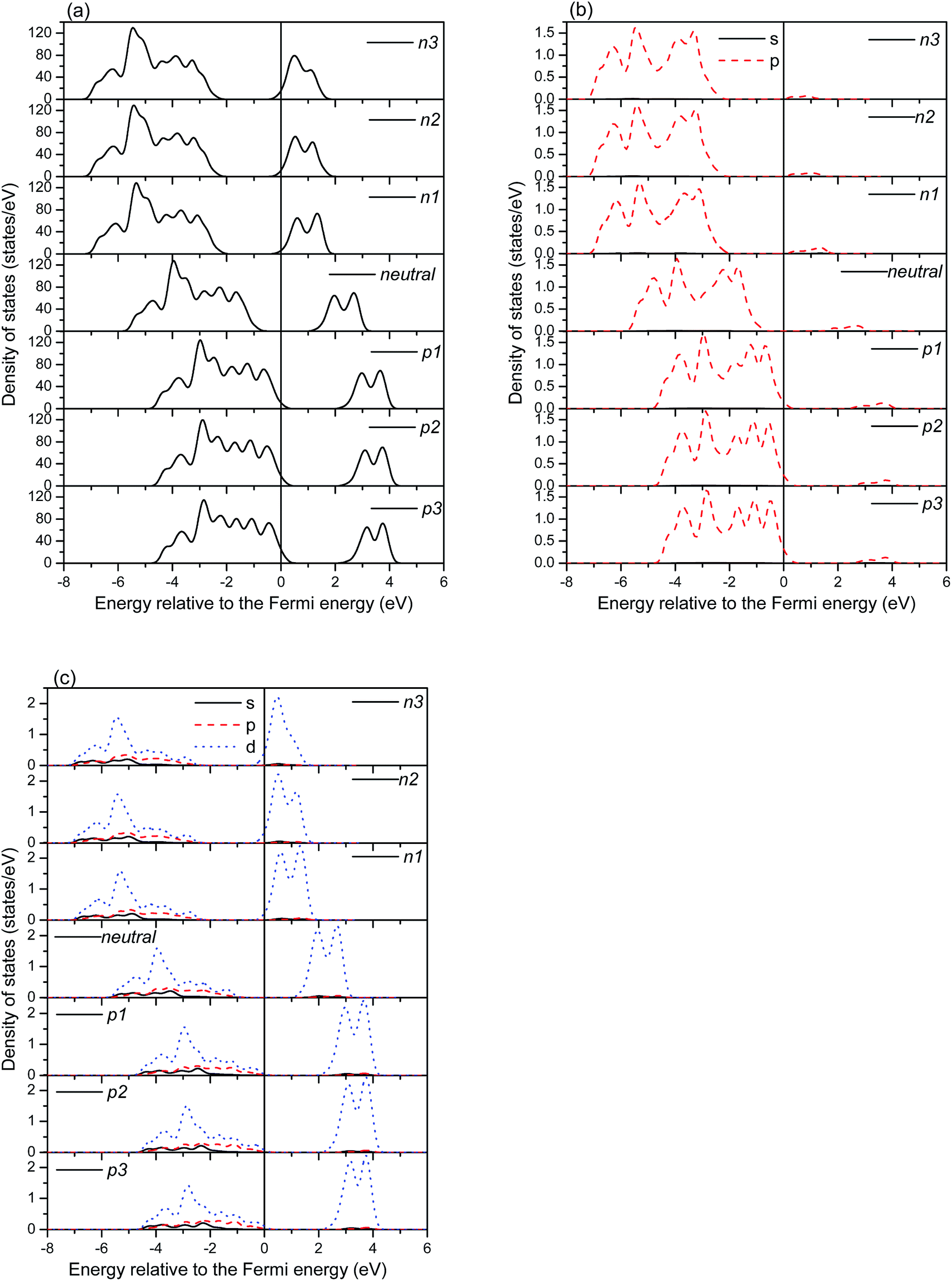
Fig. 8 shows the DOSs of the hydrogen atom passivated nanotubes. The bonding peaks of the hydrogen atoms in the (6, 0) nanotubes are obviously broadening, and the additional charge slightly alters the distributions of the bonding peaks. For the (0, 3) nanotubes, the distributions of the bonding peaks of the hydrogen atoms are more concentrated than those in the (6, 0) nanotubes. Furthermore, the bonding peaks of the p3 charged systems are much sharper than the others, indicating stronger bonding interactions between the hydrogen atoms and tubes. The average adsorption energies of the hydrogen atoms, as shown in Table 2, are very consistent with these distributions of the bonding peaks. It is worth noting that there are a few distributions of the DOSs at the Fermi energy level, which is consistent with the observations of Lin et al.24 Therefore, the adsorption of hydrogen atoms may cause a semiconductor-to-metal transition of the TNTs.24
 | ||
| Fig. 8 The density of states of the hydrogen passivated TiO2 nanotubes. | ||
The above analysis on the electronic structures reveals that the influence of hydrogen atom passivation is really localization, and the H atoms are only bonded with their neighbouring oxygen atoms. The additional charges (negative or positive) are distributed uniformly around the inner and outer walls of the nanotubes. Therefore, there is no significant difference in the electronic structures between the smaller nanotubes ((0, 3) and (6, 0)) and larger nanotubes ((0, 6) and (9, 0)). The information about the electronic structures of the (0, 6) and (9, 0) nanotubes is shown in Fig. S1–S5 of ESI.†
4. Conclusion
In this study, first principles calculations have been performed to investigate the electronic characteristics of hydrogen atom passivated and charge containing TiO2 nanotubes. The diameters of the nanotubes are slightly changed by the value of the charge, especially the negatively charged (0, 3) nanotubes with about a 0.4 Å change in the diameter. In terms of the stability of the charged systems, the negatively charged (6, 0) nanotubes and the p1 and n1 charged (0, 3) nanotubes show small formation energies, and therefore, they can be formed easily. For the hydrogen atom passivated nanotubes, the adsorbed hydrogen atoms can easily donate their electrons and make the surface of the TiO2 nanotubes positively charged. Both the charge and passivated hydrogen atoms induce a concentration of the charge around the central axis, and cause a semiconductor to metallic transition, which may affect the physico-chemical properties of the TiO2 nanotubes.Acknowledgements
This work was supported by the National Basic Research Programme of China, Grant No. 2011CB606400-G, the Natural Science Foundation of Shandong, China, Grant No. ZR2014EMM013, the Natural Science Foundation of Shandong, China, Grant No. ZR2014EMQ009, and the Fundamental Research Funds for the Central Universities Grant No. HIT.KITP.2014030. Simulations were performed using HPC resources in the CAS Shenyang Supercomputing Center.References
- A. Fujishima and K. Honda, Nature, 1972, 238, 37 CrossRef CAS PubMed.
- B. O’Regan and M. A. Grätzel, Nature, 1991, 353, 737 CrossRef.
- K. E. Sickafus, L. Minervini, R. W. Grimes, J. A. Valdez, M. Ishimaru, F. Li, K. J. McClellan and T. Hartmann, Science, 2000, 289, 748 CrossRef CAS PubMed.
- R. Poulomi, B. Steffen and S. Patrik, Angew. Chem., Int. Ed., 2011, 50, 2904 CrossRef PubMed.
- Y. Xia, P. Yang, Y. Sun, Y. Wu, B. Mayers, B. Gates, Y. Yin, F. Kim and H. Yan, Adv. Mater., 2003, 15, 353 CrossRef CAS.
- P. Hoyer, Langmuir, 1996, 12, 1411 CrossRef CAS.
- K. Shankar, G. K. Mor, H. E. Prakasam, S. Yoriya, M. Paulose, O. K. Varghese and C. A. Grimes, Nanotechnology, 2007, 18, 065707 CrossRef.
- D. Gong, C. A. Grimes, O. K. Varghese, W. Hu, R. S. Singh, Z. Chen and E. C. Dickey, J. Mater. Res., 2001, 16, 3331 CrossRef CAS.
- M. Adachi, Y. Murata, I. Okada and S. Yoshikawa, J. Electrochem. Soc., 2003, 150, G488 CrossRef CAS.
- Q. Q. Meng, Z. Y. Guan, J. Huang, Q. X. Li and J. L. Yang, Phys. Chem. Chem. Phys., 2014, 16, 11519 RSC.
- X. Pan, Q. X. Cai, W. L. Chen, G. L. Zhuang, X. N. Li and J. G. Wang, Comput. Mater. Sci., 2013, 67, 174 CrossRef CAS.
- F. Yuan, H. F. Zhang, S. X. Lu and W. G. Xu, Surf. Sci., 2014, 628, 126 CrossRef CAS.
- V. E. Henrich and R. L. Kurtz, Phys. Rev. B: Condens. Matter Mater. Phys., 1981, 23, 6280 CrossRef CAS.
- M. Kunat, U. Burghaus and C. Wöll, Phys. Chem. Chem. Phys., 2004, 6, 4203 RSC.
- S. Suzuki, K. I. Fukui, H. Onishi and Y. Iwasawa, Phys. Rev. Lett., 2000, 84, 2156 CrossRef CAS PubMed.
- T. Fujino, M. Katayama, K. T. Inudzuka and K. Okuno, Appl. Phys. Lett., 2001, 79, 2716 CrossRef CAS.
- E. Z. Liu, Y. Gao, N. Q. Zhao, J. J. Li, C. N. He and C. S. Shi, J. Appl. Phys., 2013, 113, 153708 CrossRef.
- M. Paulose, O. K. Varghese, G. K. Mor, C. A. Grimes and K. G. Ong, Nanotechnology, 2006, 17, 398 CrossRef CAS.
- O. K. Varghese, D. W. Gong, M. Paulose, K. G. Ong and C. A. Grimes, Sens. Actuators, B, 2003, 93, 338 CrossRef CAS.
- E. Sennik, Z. Colak, N. Kilinc and Z. Z. Ozturk, Int. J. Hydrogen Energy, 2010, 35, 4420 CrossRef CAS.
- J. Lee, D. H. Kim, S. H. Hong and J. Y. Jho, Sens. Actuators, B, 2011, 160, 1494 CrossRef CAS.
- O. K. Varghese, D. W. Gong, M. Paulose, K. G. Ong, E. C. Dickey and C. A. Grimes, Adv. Mater., 2003, 15, 624 CrossRef CAS.
- J. M. Macak, F. Schmidt-Stein and P. Schmuki, Electrochem. Commun., 2007, 9, 1783 CrossRef CAS.
- F. Lin, G. Zhou, Z. Y. Li, J. Li, J. Wu and W. H. Duan, Chem. Phys. Lett., 2009, 475, 82 CrossRef CAS.
- J. G. Wang, L. Wang, L. Ma, J. J. Zhao, B. L. Wang and G. H. Wang, Phys. E, 2009, 41, 838 CrossRef CAS.
- Y. Tsutsumi, D. Nishimura, H. Doi, N. Nomura and T. Hanawa, Mater. Sci. Eng., C, 2009, 29, 1702 CrossRef CAS.
- M. E. P. Souza, L. Lima, C. R. P. Lima, C. A. C. Zavaglia and C. M. A. Freire, J. Mater. Sci.: Mater. Med., 2009, 20, 549 CrossRef CAS PubMed.
- H. Suito, Y. Iwawaki, T. Goto, Y. Tomotake and T. Ichikawa, PLoS One, 2013, 8, e66052 CAS.
- R. Asahi, T. Morikawa, T. Ohwaki, K. Aoki and Y. Taga, Science, 2001, 293, 269 CrossRef CAS PubMed.
- A. Malashevich, M. Jain and S. G. Louie, Phys. Rev. B: Condens. Matter Mater. Phys., 2014, 89, 075205 CrossRef.
- E. Finazzi, C. D. Valentin, G. Pacchioni and A. Selloni, J. Chem. Phys., 2008, 129, 154113 CrossRef PubMed.
- H. Taro, K. Hideyuki, Y. Koichi, N. Hiroyuki and F. Yutaka, et al., Appl. Phys. Express, 2008, 1, 111203 CrossRef.
- K. Yang, Y. Dai, B. B. Huang and Y. P. Feng, J. Phys. D: Appl. Phys., 2014, 47, 275101 CrossRef.
- Z. Pászti, T. Keszthelyi, O. Hakkel and L. Guczi, J. Phys.: Condens. Matter, 2008, 20, 224014 CrossRef.
- R. Simón-Vázquez, T. Lozano-Fernández, M. Peleteiro-Olmedo and Á. González-Fernández, Colloids Surf., B, 2014, 113, 198 CrossRef PubMed.
- A. M. Sultan, Z. E. Hughes and T. R. Walsh, Langmuir, 2014, 30, 13321 CrossRef CAS PubMed.
- G. K. Mor, O. K. Varghese, M. Paulose and C. A. Grimes, Adv. Funct. Mater., 2005, 15, 1291 CrossRef CAS.
- K. Shankar, G. K. Mor, H. E. Prakasam, S. Yoriya, M. Paulose, O. K. Varghese and C. A. Grimes, Nanotechnology, 2007, 18, 065707 CrossRef.
- Q. Y. Cai, M. Paulose, O. K. Varghese and C. A. Grimes, J. Mater. Res., 2005, 20, 230 CrossRef CAS.
- A. Vittadini, M. Casarin and A. Selloni, Theor. Chem. Acc., 2007, 117, 663 CrossRef CAS.
- F. M. Hossain, A. V. Evteev, I. V. Belova, J. Nowotny and G. E. Murch, Adv. Appl. Ceram., 2012, 111, 72 CrossRef CAS.
- G. H. Du, Q. Chen, R. C. Che, Z. Y. Yuan and L. M. Peng, Appl. Phys. Lett., 2001, 79, 3702 CrossRef CAS.
- Y. Q. Wang, G. Q. Hu, X. F. Duan, H. L. Sun and Q. K. Xue, Chem. Phys. Lett., 2002, 365, 427 CrossRef CAS.
- D. Szieberth, A. M. Ferrari, Y. Noel and M. Ferrabone, Nanoscale, 2010, 2, 81 RSC.
- A. V. Bandura and R. A. Evaresto, Surf. Sci., 2009, 603, L117 CrossRef CAS.
- G. Kresse and J. Hafner, Phys. Rev. B: Condens. Matter Mater. Phys., 1993, 47, 558 CrossRef CAS.
- G. Kresse and J. Furthmüller, Phys. Rev. B: Condens. Matter Mater. Phys., 1996, 54, 11169 CrossRef CAS.
- P. E. Blöchl, Phys. Rev. B: Condens. Matter Mater. Phys., 1994, 50, 17953 CrossRef.
- M. Stamate, G. Lazar and I. Lazar, Rom. J. Phys., 2008, 53, 217 CAS.
- A. D. Becke and K. E. Edgecombe, J. Chem. Phys., 1990, 92, 5397 CrossRef CAS.
- A. Savin, R. Nesper, S. Wengert and T. F. Fässler, Angew. Chem., Int. Ed. Engl., 1997, 36, 1808 CrossRef CAS.
Footnote |
| † Electronic supplementary information (ESI) available. See DOI: 10.1039/c6ra00235h |
| This journal is © The Royal Society of Chemistry 2016 |