Bandgap engineering of MoS2/MX2 (MX2 = WS2, MoSe2 and WSe2) heterobilayers subjected to biaxial strain and normal compressive strain
Xiangying Su*a,
Weiwei Jua,
Ruizhi Zhangb,
Chongfeng Guo*b,
Jiming Zhengb,
Yongliang Yonga and
Xiaohong Lia
aSchool of Physics & Engineering, Henan University of Science & Technology, 263 Kaiyuan Road, Luoyang, 471023, China. E-mail: xiangyingsu@126.com
bNational Key Laboratory of Photoelectric Technology and Functional Materials (Culture Base) in Shaanxi Province, National Photoelectric Technology and Functional Materials & Application of Science and Technology International Cooperation Base, Institute of Photonics & Photon-Technology, Department of Physics, Northwest University, Xi’an 710069, China. E-mail: guocf@nwu.edu.cn
First published on 2nd February 2016
Abstract
Using first-principles calculations, we studied the electronic properties of quasi-2D MoS2/MX2 (MX2 = WS2, MoSe2 and WSe2) heterobilayers, focusing on engineering the band gap via application of in-plane biaxial strain and out-of-plane normal compressive strain (NCS). All heterobilayers show semiconducting characteristics with an indirect band gap except for the MoS2/WSe2 system which exhibits direct band gap character. The band gaps can all be widely tuned through strain and semiconductor–metal transitions can occur. In particular the direct band gap can be tuned and an appropriate compressive strain can tune the direct band gap of MoS2/WSe2 and MoS2/MoSe2, but MoS2/WS2 does not exhibit a direct band gap under any circumstances.
1. Introduction
Layered transition-metal dichalcogenides (TMDs) have attracted great interest because of their analogous structure with graphene and their novel electronic properties.1,2 Depending on the combination of chalcogen and metal atoms, TMDs form a wide range of two-dimensional (2D) materials: superconductors,3 metals,4 Mott insulators,5 charge-density-wave systems,6 and semiconductors.7,8 Semiconducting 2D TMDs include MoS2, MoSe2, MoTe2, WS2 and WSe2 and have been regarded as promising materials for comprehensive applications.9,10 Many physical and chemical properties of these TMD semiconductors including the change in their properties with chalcogen/metal composition have been widely investigated.11–16 For example, the electrochemical properties strongly depend on the metal-to-chalcogen composition.14,15 Furthermore, the toxicity of these materials has been studied too.17,18 All of the above reports are useful and make a good foundation for practical applications. For these semiconductors’ applications in optoelectronics, tunable electronic properties are crucial. If the band gap can be tuned, meaning that a semiconductor with a lower band gap or a semiconductor-to-metal transition can be obtained, nanodevices with a wide range of tunable band gaps may be fabricated. In order to achieve tunable electronic properties, heterostructures have been widely constructed for the conventional semiconductors. Various 2D materials have been successfully isolated in recent years,19,20 raising the possibility of designing van der Waals 2D heterostructures, with TMD-based hybrid multilayered structures being identified as prototype van der Waals heterostructures.21–23 Recently, TMD/TMD heterostructures such as WS2/MoS2 and WSe2/MoSe2 heterobilayers have been successfully synthesized and been characterized using both photoluminescence and Raman spectroscopy.24,25 Moreover, computational studies have suggested that the band gap can be engineered by building TMD/TMD heterostructures.26–28 For example, the bilayer heterostructure composed of a MoS2 monolayer and a WS2 monolayer has a smaller band gap than the value of either constituent component, owing to the band offset.27 The electronic band structure of nanoscale multilayer TMDs heterostructures (MoX2)n(MoY2)m (X, Y = S, Se or Te), depend sensitively on the choice of constituent components and their relative thicknesses, because of the intrinsic mismatch strain and spontaneous electrical polarization at the interface of the heterostructures.28Though the electronic properties of TMD/TMD heterostructures have been studied, few reports focus on band gap tuning using external strain. Recent theoretical investigations have revealed that strain is an effective and promising tool to control the electronic properties of 2D TMD materials.29–31 Moreover, strain engineering has been recognized as one of the best possible strategies to modulate the band gap, since it neither ineffectualizes the single layer nor attenuates the properties.32,33 The strain can be induced easily through growing 2D TMD materials on flexible substrates.34 In the current work, we will investigate the electronic properties of MoS2/MX2 (MX2 = WS2, MoSe2 and WSe2) heterobilayers and the effect of the external strain on the electronic properties by using first-principles calculations in the framework of density functional theory (DFT). Strain will be applied to the ultrathin heterobilayers in the direction parallel to the sheets (in-plane biaxial strain, including tensile and compressive strain) and perpendicular to the sheets (out-of-plane normal compressive strain). The physical mechanism of the electronic structure variation of the MoS2/MX2 heterobilayers will be studied too.
2. Model and calculation methods
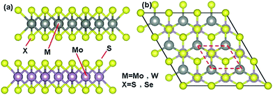
The geometry optimization and electronic properties were calculated by using DFT as implemented in the Vienna ab-initio simulation package (VASP).35,36 Electron–ion interactions were accounted for by use of projector-augmented-wave (PAW) potentials,37 while the generalized gradient approximation (GGA) in the scheme of Perdew–Burke–Ernzerhof (PBE)38 was used to treat the electron exchange–correlation interactions. The weak van der Waals (vdWs) interaction between the monolayers was introduced into our calculations by adding a semiempirical dispersion potential (through a pairwise force field following Grimme’s DFT-D2 method39) as implemented in VASP. The structural relaxations were performed by using a conjugate gradient algorithm with a force tolerance of 0.01 eV Å−1. Electronic minimization was performed with a tolerance of 10−5 eV. The kinetic energy cutoff was set at 400 eV for all the calculations. A K-point sampling of 11 × 11 × 1 was used for the relaxation calculations; a 31 × 31 × 1 Monkhorst–Pack mesh was used post-relaxation for generating accurate charge densities and the density of states. A vacuum of 30 Å, which was found to be sufficient, was introduced to avoid interaction between periodic images of slabs in the z-direction.We have three types of heterobilayers, i.e. MoS2/WS2, MoS2/MoSe2, and MoS2/WSe2, which consist of a MoS2 monolayer and an MX2 (WS2, MoSe2 and WSe2) monolayer as shown in Fig. 1(a). The most energy favorable configuration of these heterobilayers, i.e. the relative position of the two monolayers, was determined by using the following methods: the MoS2 monolayer was fixed and the MX2 monolayer was moved both in the in-plane and out-of-plane directions, and the total energy at each step was calculated. The results are shown in Fig. 2 and Table 1. It should be stated that in the in-plane direction only the irreducible region26,40 was considered due to the period conditions, as indicated by the red lines in Fig. 1(b).
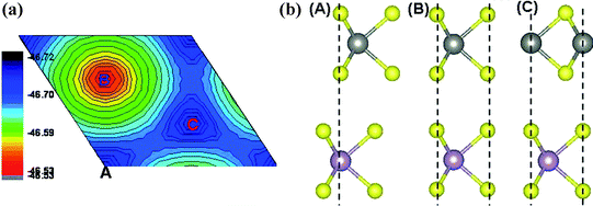 | ||
| Fig. 2 (a) The total energy landscape of the MoS2/WS2 heterobilayers within the irreducible region shown in Fig. 1(b). (b) The stacking pattern of the MoS2 monolayer and the WSe2 monolayer. | ||
| MoS2/WS2 | MoS2/MoSe2 | MoS2/WSe2 | |
|---|---|---|---|
| a (Å) | 3.178 | 3.266 | 3.256 |
| c (Å) | 12.458 | 12.662 | 12.670 |
| Eg (eV) | 1.097 | 0.698 | 0.601 |
Fig. 2(a) displays the energy landscape in the irreducible region of the MoS2/WS2 heterobilayer. There are 3 special points, as indicated by A, B and C, which are the configurations in which X atoms locate right above Mo atoms, M atoms locate right above Mo atoms, and M atoms locate right above S atoms, respectively, as shown in Fig. 2(b) (A)–(C). As shown in Fig. 2(a), B has the highest total energy so is the most unstable, while C is the most stable configuration. For the other two heterobilayers, the C configuration is also the most stable one. Therefore in the following investigations, only the C configuration is considered. Then the total energy of all heterobilayers as functions of the lattice constants a and c were calculated and the optimum values were obtained as listed in Table 1.
3. Results and discussion
3.1 Electronic structures of the MoS2/MX2 heterobilayers
The electronic structures of the MoS2/MX2 heterobilayers were calculated first. As shown in Fig. 3, only the MoS2/WSe2 heterobilayer possesses a direct band gap of 0.60 eV, whereas the MoS2/WS2 and MoS2/MoSe2 heterobilayers are indirect semiconductors similar to their bilayers with the CBM located at the K point and the VBM located at the Γ point. For the MoS2/WSe2 heterobilayer, the VBM is still located at the K point. For all heterobilayers, the density of states indicate that the CBM are all localized on the MoS2 monolayer and the VBM are localized on the MX2 monolayer, forming type II heterostructures, which may be advantageous for the separation of electron–hole pairs and is useful for light detection and harvesting.22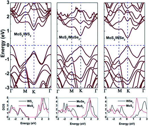 | ||
| Fig. 3 Band structures and local density of states of the MoS2/MX2 (MX2 = WS2, MoSe2 and WSe2) heterobilayers. | ||
3.2 Application of in-plane biaxial strain
In-plane biaxial strain on the MoS2/MX2 heterobilayers was applied by changing the cell parameters (a and b, equally), relaxing the structure along the c-axis, and the biaxial strain was calculated as ε = Δa/a0, where a0 and Δa + a0 are equilibrium and instantaneous cell parameters, respectively. As illustrated in Fig. 4, a first general variation for the band structures of strained MoS2/MX2 heterobilayers is the reduction of the band gap with increasing applied strain (both tensile and compressive), and eventually the semiconductor–metal transition is predicted, confirming previous calculations on the variation of the band gap as functions of the strained monolayer and the MoS2 bilayer.29,30 We also noted that compared to MoS2/MoSe2 and MoS2/WSe2, the MoS2/WS2 heterobilayer requires more tensile and compressive strain to attain the semiconductor–metal transition.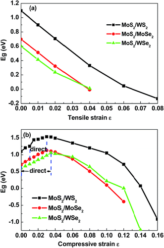 | ||
| Fig. 4 Plots of energy band gap (Eg) versus applied in-plane biaxial strain for MoS2/MX2 (MX2 = WS2, MoSe2, WSe2) heterobilayers: (a) tensile strain and (b) compressive strain. | ||
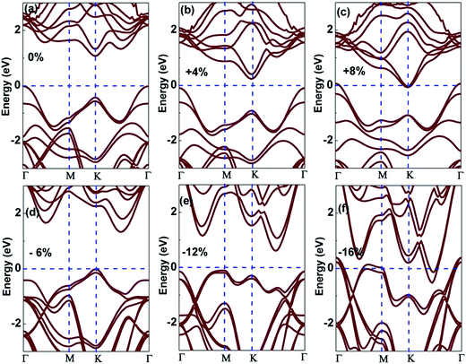
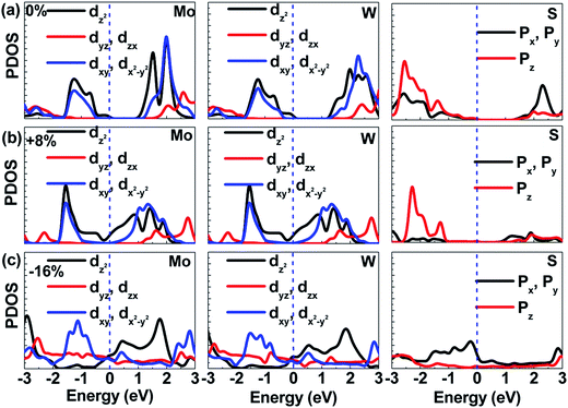
For better revealing the changes of the electronic properties of MoS2/MX2 heterobilayers under the applied strain, we studied in detail the variations of the band structure and the partial density of states (PDOS). Taking the MoS2/WS2 heterobilayer as an example the selected results are presented in Fig. 5 and 6. From Fig. 5 we can see that in the case of tensile strain, the significant changes in the band structure can be related to shifts in the energy states of the conduction band near the K point, and of the valence band near the K and Γ points. The conduction and valence band at the K point drop substantially with increasing applied strain, nevertheless the top of the valence band at the Γ point drop at first and then rise. Analysis of the PDOS indicates that these states are mainly described by S 3p and Mo and W 4d orbitals (see Fig. 6(a)). Due to the applied tensile strain the distance between the atoms change, resulting in a different superposition of the atom orbitals and then leading to shifts of the energy of these states. With an 8% biaxial tensile strain, the CBM at the K point and the VBM at the Γ point cross the Fermi level and semiconductor–metal transition occurs (see Fig. 5(c) and 6(b)).
We also noted that when tensile biaxial strain is applied all MoS2/MX2 heterobilayers considered in this study exhibit indirect band gap character. As mentioned above, under the equilibrium state the MoS2/WSe2 heterobilayer has a direct band gap. Nevertheless, a very small (0.5%) applied tensile strain can cause the MoS2/WSe2 heterobilayer to change into an indirect semiconductor as the VBM is relocated at the Γ point from the K point with the valence at the K point dropping. In essence, this is due to the fact that the energy difference between the valence band at the K point and the Γ point is very small for the unstrained MoS2/WSe2 heterobilayer and a slight change in the distance between the atoms under strain is sufficient to shift the energy states, breaking the direct band gap symmetry.
In the case of compressive biaxial strain a different trend for the shifts of the band gap is observed (see Fig. 4). For a relatively small strain, compressive and tensile strain show opposite effects on the band structure: the band gap is reduced when tensile strain is applied to all the heterobilayers, but it is increased under compressive strain. Under compressive strain, direct band gaps appear in the MoS2/WSe2 and MoS2/MoSe2 systems with ε in the range of 0–3.5% and 1–3%, respectively. The variation of the band structure was analyzed with the MoS2/WS2 heterobilayer as the chosen example, as shown in Fig. 5. Both the top of the valence band near the Γ point and the bottom of the conduction band between the K and Γ points drop substantially with increasing applied compressive strain. In contrast, the valence and conduction bands at the K point rise (see Fig. 5(d)). When the stain is below 3.5%, the CBM and VBM of the MoS2/WSe2 system are invariably located at the K point, indicating its direct band gap character. For the MoS2/MoSe2 system with a strain range of 1–3%, the CBM is still located at the K point and the VBM is located at the K point from the Γ point, so it takes on a direct band gap. However, under compressive strain the MoS2/WS2 system does not have a direct band gap. With further increasing the applied compressive strain, the top of the valence band at the Γ point rises again and ultimately crosses the Fermi level (see Fig. 5(e) and (f)). When a small compressive strain is applied, only the energy states at the edge of the band gap (primarily described by the pz orbitals of chalcogen atoms and dz2 orbitals of metal atoms) are involved. When larger compressive strain is applied, overlapping of the in-plane xy atomic orbitals is much more significant and consequently for the inner energy states the shift of the energy is also considerable. With a 16% biaxial compressive strain applied to the MoS2/WS2 system, the shift of the inner energy bands is so great that the bottom of the conduction band and the top of the valence band cross the Fermi level, as illustrated in Fig. 5(f) and 6(c). In the case of compressive strain, the semiconductor–metal transition thus also occurs, but involves a slightly different physical mechanism compared to that of tensile strain.
3.3 Application of out-of-plane normal compressive strain (NCS)
Next, the band gaps of the semiconducting MoS2/MX2 heterobilayers were investigated as a function of the out-of-plane NCS, and the strain ε was defined as (d0 − d)/d0, where d0 and d are the unstrained and strained interlayer distances, respectively. The results of band gap versus NCS are summarized in Fig. 7. It can be found that with increasing NCS the band gaps in all the cases monotonically decrease, and eventually fall below zero, indicating the occurrence of the semiconductor–metal transition. Moreover, under any NCS all of the MoS2/MX2 heterobilayers do not show direct band gap character, even for the MoS2/WSe2 heterobilayer a small normal strain can cause its inherent direct band gap to vanish. We also note that the MoS2/WS2 heterobilayer still requires more NCS to attain the semiconductor–metal transition than the MoS2/MoSe2 and MoS2/WSe2 heterobilayers.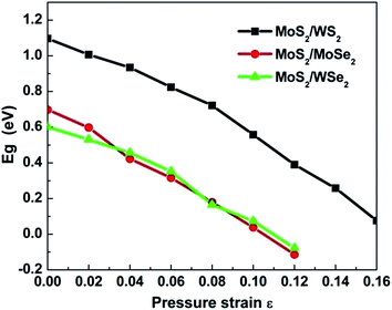 | ||
| Fig. 7 Band gap (Eg) as a function of the applied normal compressive strain ε for MoS2/MX2 (MX2 = WS2, MoSe2 and WSe2) heterobilayers. | ||
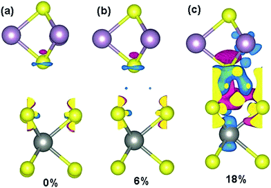
To gain insight into the variation of electronic properties with NCS, band structures and PDOS of selected cases (ε = 0%, 6% and 18%) are presented in Fig. 8, and MoS2/WS2 is still selected as an example from the MoS2/MX2 heterobilayers. The significant changes of the band structure are related to the shifts of the energy states at the K and the Γ points. The conduction and valence bands at the K point drop substantially with increasing applied NCS, while the top of the valence band at the Γ point rises. The VBM values at Γ mainly originate from W and Mo dz2 and S pz orbitals and the states have anti-bonding character (see Fig. 8(a)). On applying NCS and decreasing the interlayer distance of the heterobilayer, the MoS2 monolayer and WS2 monolayer interaction increases and raises the energy of the anti-bonding states; consequently, the VBM at Γ slightly shifts upwards. The increasing interaction between the two monolayers causes the bands to broaden, as a result the CBM shifts downwards and ultimately to the Fermi level, and the shift of the CBM is mainly responsible for the variation of the band gap. In short, the VBM at the Γ point rising and the CBM at the K point falling toward the Fermi level causes the band gap to decrease and ultimately causes the semiconductor–metal transition. Or alternatively, the ever-increasing interlayer interaction with NCS is mainly responsible for the band gap decreasing and closing.
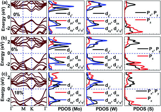 | ||
| Fig. 8 Band structures and PDOS of Mo, W and S for the MoS2/WS2 heterobilayer at (a) 0, (b) 6%, and (c) 18% normal compressive strain. | ||
The above conclusion was supported through the redistribution of charges under NCS. The charge density difference can be calculated from
| Δρ = ρMoS2/WS2 − ρMoS2 − ρWS2 |
4. Conclusions
In conclusion, the electronic properties of quasi-2D MoS2/MX2 (MX2 = WS2, MoSe2 and WSe2) heterobilayers have been investigated, focusing on the consequences of in-plane biaxial strain (including tensile and compressive strains) and out-of-plane NCS. Our calculations suggest that MoS2/MX2 heterobilayers are indirect-bandgap semiconductors except for the MoS2/WSe2 system which can retain the direct-bandgap character of the constituent monolayer. Either biaxial strain or NCS can induce modulation of the band gap for all of the heterobilayer systems. The band gaps decrease with increasing strain and beyond a critical strain, the semiconductor–metal transition can occur. In particular, strain can induce the modulation of direct band gap character. Specifically, for the MoS2/WSe2 system, the direct band gap character is maintained in an in-plane compressive strain range of 0 to 3.5%. For the MoS2/MoSe2 system, a direct band gap can also be obtained in an in-plane compressive strain range of 1 to 3%. However, the MoS2/WS2 system does not exhibit a direct band gap under any strain. These theoretical predictions suggest that TMD heterobilayer materials are very promising for optoelectronic applications due to their tunable band gaps by applying strain, the tunable direct band gap of the MoS2/WSe2 heterobilayer and a possible indirect-to-direct band gap transition in the MoS2/MoSe2 heterobilayer using compressive biaxial strain.Acknowledgements
This work was supported by the National Natural Science Foundation of China (No. 11547153, 11404096), the Youth Foundation of Henan University of Science and Technology (No.13350038), the Innovation Team of Henan University of Science and Technology (No. 2015XTD001) and the International Science and Technology Cooperation Projects of Henan Province (152102410035).References
- K. F. Mak, C. Lee, J. Hone, J. Shan and T. F. Heinz, Phys. Rev. Lett., 2010, 105, 136805 CrossRef PubMed.
- A. Ramasubramaniam, D. Naveh and E. Towe, Phys. Rev. B: Condens. Matter Mater. Phys., 2011, 84, 205325 CrossRef.
- E. Morosan, H. W. Zandbergen, B. S. Dennis, J. W. G. Bos, Y. Onose, T. Klimczuk, A. P. Ramirez, N. P. Ong and R. J. Cava, Nat. Phys., 2006, 2, 544–550 CrossRef CAS.
- Y. Ding, Y. Wang, J. Ni, L. Shi and W. Tang, Phys. B, 2011, 406, 2254–2260 CrossRef CAS.
- A. F. Kusmartseva, A. Akrap, H. Berger, L. Forro and E. Tutis, Nat. Mater., 2008, 7, 960–965 CrossRef PubMed.
- W. Z. Hu, G. Li, J. Yan, H. H. Wen, G. Wu, X. H. Chen and N. L. Wang, Phys. Rev. B: Condens. Matter Mater. Phys., 2007, 76, 045103 CrossRef.
- S. W. Han, H. Kwo, S. K. Kim, S. Ryu, W. S. Yun, D. H. Kim, J. H. Hwang, J.-S. Kang, J. Baik, H. J. Shin and S. C. Hong, Phys. Rev. B: Condens. Matter Mater. Phys., 2011, 84, 045409 CrossRef.
- J. G. He, K. Hummer and C. Franchini, Phys. Rev. B: Condens. Matter Mater. Phys., 2014, 89, 075409 CrossRef.
- A. Splendiani, L. Sun, Y. Zhang, T. Li, J. Kim, C.-Y. Chim, G. Galli and F. Wang, Nano Lett., 2010, 10, 1271–1275 CrossRef CAS PubMed.
- B. Radisavljevic, A. Radenovic, J. Brivio, V. Giacometti and A. Kis, Nat. Nanotechnol., 2011, 6, 147–150 CrossRef CAS PubMed.
- A. Ambrosi, Z. Sofer and M. Pumera, Chem. Commun., 2015, 51, 8450–8453 RSC.
- C. C. Mayorga-Martinez, A. Ambrosi, A. Y. S. Eng, Z. Sofer and M. Pumera, Electrochem. Commun., 2015, 56, 24–28 CrossRef CAS.
- A. Ambrosi, Z. Sofer and M. Pumera, Small, 2015, 11, 605–612 CrossRef CAS PubMed.
- A. H. Loo, A. Bonanni, Z. Sofer and M. Pumera, Electrochem. Commun., 2015, 50, 39–42 CrossRef CAS.
- A. Y. S. Eng, A. Ambrosi, Z. Sofer, P. Šimek and M. Pumera, ACS Nano, 2014, 8, 12185–12198 CrossRef CAS PubMed.
- S. Li, S. Wang, D. Tang, W. Zhao, H. Xu, L. Chu, Y. Bando, D. Golberg and G. Eda, Appl. Mater. Today, 2015, 1, 60–66 CrossRef.
- E. L. K. Chng, Z. Sofer and M. Pumera, Nanoscale, 2014, 6, 14412–14418 RSC.
- W. Z. Teo, E. L. K. Chng, Z. Sofer and M. Pumera, Chem.–Eur. J., 2014, 20, 9627–9632 CrossRef CAS PubMed.
- J. N. Coleman, M. Lotya and A. O’Neil, et al., Science, 2011, 331, 568–571 CrossRef CAS PubMed.
- Z. Zeng, Z. Yin, X. Huang, H. Li, Q. He, G. Lu, F. Boey and H. Zhang, Angew. Chem., Int. Ed., 2011, 50, 11093–11097 CrossRef CAS PubMed.
- H. Fang, C. Battaglia, C. Carraro, S. Nemask, B. Ozdol, J. S. Kang, H. A. Bechtel, S. B. Desai, F. Kronast, A. A. Unal, G. Conti, C. Conlon, G. K. Palsson, M. C. Martin, A. M. Minor, C. S. Fadley, E. Yablonovitch, R. Maboudian and A. Javey, Proc. Natl. Acad. Sci. U. S. A., 2014, 111, 6198–6202 CrossRef CAS PubMed.
- H. P. Komsa and A. V. Krasheninnikov, Phys. Rev. B: Condens. Matter Mater. Phys., 2013, 88, 085318 CrossRef.
- J. Kang, J. B. Li, S. S. Li, J. B. Xia and L. W. Wang, Nano Lett., 2013, 13, 5485–5490 CrossRef CAS PubMed.
- Y. J. Gong, J. H. Lin, X. L. Wang, G. Shi, S. D. Lei, Z. Lin, X. L. Zou, G. L. Ye, R. Vajtai, B. I. Yakobson, H. Terrones, M. Terrones, B. K. Tay, J. Lou, S. T. Pantelides, Z. Liu, W. Zhou and P. M. Ajayan, Nat. Mater., 2014, 13, 1135–1142 CrossRef CAS PubMed.
- Y. J. Gong, S. D. Lei, G. L. Ye, B. Li, Y. M. He, K. Keyshar, X. Zhang, Q. Z. Wang, J. Lou, R. Vajtai, W. Zhou and P. M. Ajayan, Nano Lett., 2015, 15, 6135–6141 CrossRef CAS PubMed.
- X. Y. Su, R. Z. Zhang, C. F. Guo, M. Guo and Z. Y. Ren, Phys. Chem. Chem. Phys., 2014, 16, 1393–1398 RSC.
- K. Kośmider and J. Fernández-Rossier, Phys. Rev. B: Condens. Matter Mater. Phys., 2013, 87, 075451 CrossRef.
- L. Z. Kou, T. Frauenheim and C. F. Chen, J. Phys. Chem. Lett., 2013, 4, 1730–1736 CrossRef CAS PubMed.
- P. Johari and V. B. Shenoy, ACS Nano, 2012, 6, 5449–5456 CrossRef CAS PubMed.
- S. Bhattacharyya and A. K. Singh, Phys. Rev. B: Condens. Matter Mater. Phys., 2012, 86, 075454 CrossRef.
- X. Y. Su, R. Z. Zhang, C. F. Guo, J. M. Zheng and Z. Y. Ren, Phys. Lett. A, 2014, 378, 745–749 CrossRef.
- F. Guinea, M. I. Katsnelson and A. K. Geim, Nat. Phys., 2010, 6, 30–33 CrossRef CAS.
- W. S. Yun, S. W. Han, S. C. Hong, G. Kim and J. D. Lee, Phys. Rev. B: Condens. Matter Mater. Phys., 2012, 85, 033305 CrossRef.
- S. M. Choi, S. H. Jhi and Y. W. Son, Nano Lett., 2010, 10, 3486–3489 CrossRef CAS PubMed.
- G. Kresse and J. Furthmuller, Phys. Rev. B: Condens. Matter Mater. Phys., 1996, 54, 11169 CrossRef CAS.
- G. Kresse and J. Furthmuller, Comput. Mater. Sci., 1996, 6, 15–50 CrossRef CAS.
- G. Kresse and D. Joubert, Phys. Rev. B: Condens. Matter Mater. Phys., 1999, 59, 1758 CrossRef CAS.
- J. P. Perdew, K. Burke and M. Ernzerhof, Phys. Rev. Lett., 1996, 77, 3865 CrossRef CAS PubMed.
- S. Grimme, J. Comput. Chem., 2006, 27, 1787–1799 CrossRef CAS PubMed.
- M. Z. Hossain, Appl. Phys. Lett., 2009, 95, 143125 CrossRef.
| This journal is © The Royal Society of Chemistry 2016 |

