 Open Access Article
Superparamagnetic [sic] nanofibers by electrospinning†
R. L. Andersson a,
L. Cabedob,
M. S. Hedenqvista,
R. T. Olssona and
V. Ström
 *c
*c
aDepartment of Fibre and Polymer Technology, KTH-Royal Institute of Technology, Stockholm, SE 100 44, Sweden
bPolymers and Advanced Materials Group (PIMA), Universitat Jaume I, Campus de Riu Sec, 12071 Castellón de la Plana, Spain
cDepartment of Materials Science and Engineering, KTH-Royal Institute of Technology, Stockholm, SE 100 44, Sweden. E-mail: valter@kth.se
First published on 16th February 2016
Abstract
The preparation of superparamagnetic thin fibers by electrospinning dispersions of nanosized magnetite (Fe3O4, SPIO/USPIO) in a PMMA/PEO polymer solution is reported. The saturation magnetization and coercivity were not affected by the concentration (0, 1, 10, 20 wt%) or fiber orientation, showing hysteresis loops with high magnetization (64 A m2 kg−1 @ 500 kA m−1) and record low coercivity (20 A m−1). AC susceptibility measurements vs. temperature at frequencies from 60 to 2 kHz confirmed superparamagnetism. The mechanical properties were only slightly dependent on the particle concentration because the nanoparticles were separately encapsulated by the polymer. A uniform fibre fracture cross section was found at all the investigated particle contents, which suggests a strong interaction at the polymer/particle interface. A theoretical value of the magnetic low field susceptibility was calculated from the Langevin function and compared with measured values. The results show a distinct but concentration-independent anisotropy, favoring magnetization along the fiber orientation with no sign of exchange interaction, explained by complete nanoparticle separation. Superparamagnetism cannot be inferred from particle size alone, so a relevant interpretation and criterion for superparamagnetism is presented, in accordance with Neel's original definition. From the measurements, it can be concluded that magnetic characterization can be used to elucidate the material morphology beyond the resolution of available microscopy techniques (TEM and SEM).
Introduction
Applications for superparamagnetic magnetite include contrast agents for Magnetic Resonance Imaging (MRI) or arsenic remediation of drinking water.1–3 Other proposed applications for magnetic fibre materials include filters with adjustable particle size discrimination, remotely actuated/operated cell growth templates or mechanical actuators e.g. loudspeaker membranes or magnetorheological liquids.4,5 Many of these applications need very soft magnetic characteristics. This is generally realised with superparamagnetic iron oxide (SPIO) or ultra-small superparamagnetic iron oxide (USPIO) particles. These particles may indeed be superparamagnetic, but supporting magnetic data are seldom reported. Instead, a common approach is to state that the particle size is smaller than a critical size and indirectly claim superparamagnetism. The critical size is the upper limit for an individual particle to be superparamagnetic, and can in theory be calculated from data on the magnetic material.6,7 For magnetite at room temperature this size is ca. 30 nm.6However, the shape of the particles, exchange interaction due to very small particle–particle distances and altered magnetic properties due to their morphology, such as surface anisotropy, can prevent the material from being truly superparamagnetic.8 It must also be remembered that the transition between superparamagnetism and ferromagnetism is very sharp.7 Particles only marginally larger than the critical size will not be superparamagnetic, creating a ferro/ferrimagnetic contribution, whereas an entirely superparamagnetic sample will show both a vanishing remanence (half height of hysteresis loop at zero field) and coercivity (half width of hysteresis loop at zero magnetization), according to Neél's definition.9,10 The absence of coercivity will constitute a conservative confirmation of the absence of a ferromagnetic contribution, in contrast to e.g. the determination of the blocking temperature that only detects the presence of a superparamagnetic contribution.11 This situation can lead to incorrect conclusions.
The objective of this work is to show that it is quite possible to integrate superparamagnetic nanoparticles into mats of electrospun fibres where neither the magnetic functionality nor the mechanical properties have been compromised. The large elongation forces developed during the fibre stretching avoid problems concerned with traditional preparation methods such as melt processing or solvent casting.12 Another benefit is that the composite material is “locked”, i.e. solidified on a timescale of the order of milliseconds, effectively eliminating aggregation.13 The chosen magnetic material was nanosized magnetite particles (Fe3O4), which is renowned for its good saturation magnetization (ca. 90 A m2 kg−1 in bulk at ambient conditions) and non-toxicity.14 The ca. 10 nm sized particles were prepared using the ‘rapid mixing’ method, which resulted in a uniform particle size, high saturation magnetization and very low coercivity, all characteristics of superparamagnetism.15 The measured coercivity of the fibers was less than 20 A m−1 (only ca. half of the earth's magnetic field), which is smaller than previously reported.16,17 The fibres were spun onto a rotating drum, which aligned the fibres parallel to its circumference, i.e. for the proper assessment of the mechanical and magnetic properties along and perpendicular to the fibre direction.18 This made it possible to assess the mechanical properties of the fibres and to shed light on the particle distribution/organization, enabling a quantitative correlation between magnetic anisotropy and fibre orientation. The aligned fibres with dispersed magnetic nanoparticles may serve as a model system for superparamagnetically functionalized composite fibres, where both the mechanical and the magnetic aspects have been addressed. Previously, only two articles have reported the numerical value for the magnetic coercivity after electrospinning.16,17
Materials and methods
Materials
For the superparamagnetic nanoparticle (SPIO) synthesis, iron(II) chloride tetrahydrate (FeCl2·4H2O, ≥98.0%, Fluka) and iron(III) chloride hexahydrate (FeCl3·6H2O, 97% ACS reagent, Sigma-Aldrich) were used. An aqueous solution of 2 M ammonium hydroxide (Alfa Aesar) was used as precipitating agent. The polymers used were polymethyl-methacrylate (PMMA) with a Mw of 410 kDa (Alfa Aesar) and polyethylene oxide (PEO) with a Mw of 600 kDa (Acros Organics), both in powder form. Dimethylformamide (DMF) (99.8%, BDH Prolabo) was used as the electrospinning solvent.Synthesis of magnetite nanoparticles
The SPIO particles were prepared by aqueous co-precipitation in which a ‘rapid mixing’ of the reactants occurred in the timeframe of milliseconds.15 Briefly, two solutions loaded in two separate syringes were simultaneously injected as converging jets into a single 0.5 mm thin tube. The two syringes contained the ammonia and the iron ion solution (the Fe3+ to Fe2+ concentration ratio was 2![[thin space (1/6-em)]](https://www.rsc.org/images/entities/char_2009.gif) :
:![[thin space (1/6-em)]](https://www.rsc.org/images/entities/char_2009.gif) 1 according to the stoichiometry in Fe3O4), and this resulted in a stable colloidal suspension of superparamagnetic magnetite nanoparticles.19 The particles were washed three times with highly purified type 1 water (18.2 MΩ cm) according to ASTM D1193. Prior to mixing with the polymer solution, a solvent exchange into DMF was performed (3 times centrifugation followed by replacement with DMF and re-dispersion).
1 according to the stoichiometry in Fe3O4), and this resulted in a stable colloidal suspension of superparamagnetic magnetite nanoparticles.19 The particles were washed three times with highly purified type 1 water (18.2 MΩ cm) according to ASTM D1193. Prior to mixing with the polymer solution, a solvent exchange into DMF was performed (3 times centrifugation followed by replacement with DMF and re-dispersion).
Preparation of the fibre solutions
The solutions to be electrospun were prepared by mixing the superparamagnetic particles suspended in DMF with the polymers. The nominal quantities of nanoparticles (SPIO), PMMA, PEO and solvent (DMF) for a total amount of ca. 10 mL spinning solution are listed in Table 1.| Sample | SPIO (g) | PMMA (g) | PEO (g) | DMF (g) |
|---|---|---|---|---|
| 0% | 0 | 0.750 | 0.250 | 9.00 |
| 1% | 0.012 | 0.854 | 0.285 | 10.3 |
| 10% | 0.092 | 0.621 | 0.207 | 7.45 |
| 20% | 0.184 | 0.552 | 0.184 | 6.62 |
The ratio of PMMA to PEO was 75/25 by weight for all the fibres prepared, since this proportion improves the PMMA fibre toughness.20,21 The solvent content was adjusted to yield a constant polymer concentration of 10 wt%. The components of the fibre solutions were added to a vial and gently stirred at room temperature for 24 hours. The suspensions were then heated to 70 °C and kept at this temperature under constant stirring for one hour before spinning.
Electrospinning and collection of fibre mats
The solutions were continuously fed from a 5 mL polypropylene syringe at a rate of 20 μL min−1, via a PTFE tube, to an 18-gauge needle with a flat tip. The needle tip was positioned 220 mm vertically above the collector. The electric potential applied between the needle and the collector was 10 kV during the electrospinning. Two different collectors were used: a stationary aluminium plate and a rotating aluminium drum 50 mm in diameter for the preparation of respectively randomly deposited and aligned fibre mats, see Fig. 1. The aligned fibre mats were obtained by depositing the electrospun fibres on the aluminium drum rotating at 2000 rpm.Characterization techniques
Scanning electron microscopy (SEM) observations were made in a Hitachi S-4800 cold-field-emission scanning electron microscope. A ca. 8 nm coating of platinum–palladium was sputtered onto the surface of the samples (40 s at 80 mA) in a Cressington 208HR high-resolution sputter. Transmission electron microscope (TEM) micrographs were acquired in a Hitachi HT-7700 high-resolution microscope operated at 100 kV. For the nanoparticle analysis, drops of a dilute aqueous nanoparticle suspension were dried over the carbon-coated grid (200 mesh formvar-carbon, Ted Pella, USA). The samples for TEM were directly electrospun over the carbon-coated copper grid.The wide-angle X-ray diffraction (WAXS) measurements were performed using a PANalytical X'Pert Pro diffractometer. The samples were scanned at room temperature in a Bragg–Brentano geometry, using Cu Kα radiation (λ = 154 pm). The data was collected over a range of scattering angles 2θ: 2–40°.
Thermo-gravimetric analysis (TGA) was conducted using a Mettler Toledo TGA/DSC 1 with 70 μL Al2O3 crucibles containing ca. 10 mg of material. The heating rate was 10 °C min−1 until a maximum temperature of 550 °C and with a nitrogen gas flow of 10 mL min−1.
The tensile measurements were carried out on the aligned fibre mats in the direction of the fibre axis in accordance with a previously reported technique.18 The sample size was 10 by 5 mm2 and the measurements were made at a strain rate of 0.5 mm min−1 (10% of sample length per minute). The stress values were calculated by dividing the measured force by the cross sectional area of the fibre mat. This cross-sectional area was calculated from the mass per unit area of the electrospun fibre mat and the density of the fibre material determined by the rule of mixtures. In order to prevent damage to the fibre mat before testing, the fibres were fixed to an aluminium template using alkoxy-ethyl-cyanoacrylate (Loctite 460, Henkel AG & Co. KGaA, Germany) prior to being clamped in the tensile tester.
Magnetic characterization
A vibrating sample magnetometer (VSM), (EG&G Princeton Applied Research model 155), was used for acquiring hysteresis loops between ±500 kA m−1. In order to obtain the parallel and perpendicular magnetic responses of the aligned electrospun superparamagnetic fibres, the fibres were collected onto a thin polyethylene film which was attached to the surface of the drum prior to spinning. This allowed rectangular pieces to be cut and rolled into small tubes (10 by 2 mm2). Depending on the rolling direction relative to the fibre orientation, the fibres could be oriented parallel to or perpendicular to the tube axis, which was kept parallel to the magnetic field. After magnetic characterization, the samples were analysed by thermogravimetry so that the correct amount of magnetic material could be assessed.Results and discussion
Superparamagnetic fiber fabrication
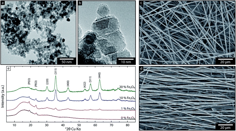
Fig. 1a and b show transmission electron micrographs of the superparamagnetic particles prior to the electrospinning. The particles were highly crystalline nanosized magnetite determined from their fringe patterns crossing the entire particles (HRTEM, Fig. 1b). The volume averaged particle diameter was 8 ± 2 nm, determined from manual measurements of more than 500 particles in TEM (histogram available in ESI Fig. S1†), and the X-ray diffraction spectra was identified as magnetite spinel phase structure (JCPDS 19-629), Fig. 1e. Fig. 1d shows that a high loading of these magnetite nanoparticles (20 wt%) resulted in a somewhat corrugated fiber surface, whereas unloaded fibers show smooth fibers, see Fig. 1c. However, the overall formation of these 1–2 μm thick and uniform electrospun fibers was not significantly affected by the incorporation of the magnetite particles. This was achieved as a result of a successful solvent exchange of the aqueous phase used for the preparation of the magnetite particles into DMF, which is miscible with water and served as an optimal carrier for the magnetite and dissolved PMMA phase during the electrospinning.In fact, all the samples with magnetite contents varying from 1 to 20 wt% could be spun into uniform fibers and aligned as unidirectional fiber mats. The wide-angle X-ray spectroscopy (WAXS) data for the composite fibre mats confirmed that the nanoparticles inside the fibres remained in their non-oxidized magnetite phase, see Fig. 1e. The peaks were from the (220), (311), (400), (422), (511) and (440) magnetite crystalline planes. The small peaks at 2θ: 19 and 23° (Fig. 1e) were due to polyethylene oxide (PEO) crystals, indicating that some phase separation occurred in all the samples. Previously, this phase separation was demonstrated to facilitate fibre necking under a tensile load, which significantly improved the fracture toughness.21 In the 20 wt% sample, these two peaks are much smaller, suggesting that the magnetite prevented the PMMA/PEO phase separation and/or induced a structure with much smaller PEO crystals. This mechanism resembles a previously demonstrated effect that silica nanoparticles restrict PEO crystal nucleation and growth when the particle content approaches 20 wt%.22 The specific surface area of the magnetite nanoparticles in this work was ca. 120 m2 g−1. This large value is consistent with the previous suggestion that the particles restrict the formation of PEO crystals.
Particle distribution within the electrospun fibres
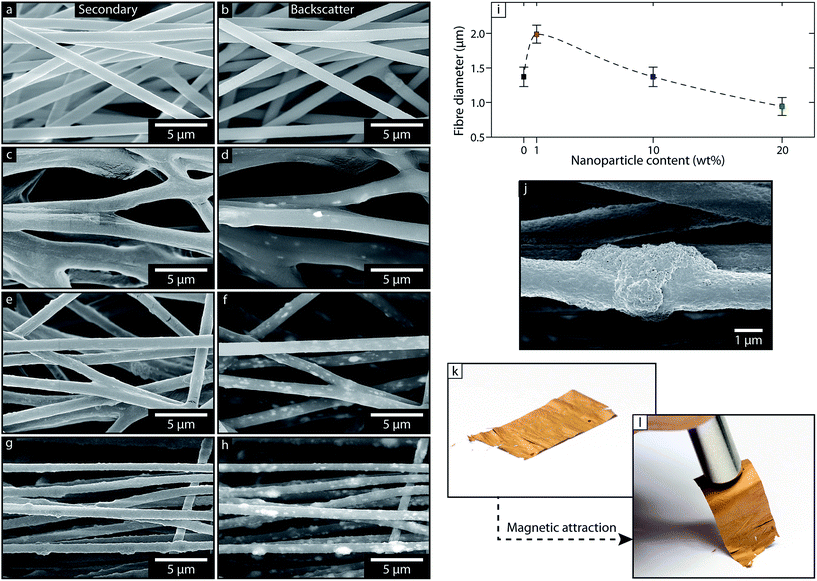
The SEM micrographs of the differently particle-loaded fibres (Fig. 2, left column) show that the polymer entirely encapsulated the nanoparticles during electrospinning. These micrographs use low energy secondary electrons to create the images and thus show images of the surface topology with little penetration depth. Fig. 2, right column, shows micrographs of the same imaged areas acquired using backscattered electrons, which have almost the same energy as the incident electron beam, but penetrate much deeper, and the scattered intensity is roughly proportional to the atomic number of the constituent elements in the sample.23 The iron (i.e. magnetite) in the sample is therefore clearly shown even if it is buried in the interior of the fibres. A significant number of the particles were present as clusters with an average size of 100 nm. Larger ca. 1 μm clusters were only apparent in the 20 wt% fibres. A higher magnification of one of the larger clusters (Fig. 2h and j) shows that these larger entities were also well encapsulated loose agglomerates.24 The wetting of the particles appeared to be good, as indicated by the absence of any delamination of the particle/polymer interface during mechanical testing (see the Mechanical section). A general characteristic with the higher filler contents was that the larger clusters often protruded from the cylindrical shape of the fibres, Fig. 2h and j. The fibre diameter depended on the particle content (Fig. 2i and ESI Fig. S2†), and showed at first a steep increase from 1.2 μm for unloaded fibres to 2 μm for the 1 wt% particle content. This was followed by a gradual decrease in diameter to ca. 1 μm with increasing particle content (10 and 20 wt%). It is suggested that the diameter increase from 0 to 1 wt% is due to a significantly stronger electric field. This can be explained by considering that the unloaded polymer liquid is an excellent electric insulator so that even a minute fraction of conductive elements from particle inclusions (or an imperfect washing/solvent exchange) can give rise to a higher conductivity. In this situation, with a conducting jet, the voltage acts over a shorter distance leading to a stronger field (between the spinneret and the collector).25 The decrease in fibre diameter with higher particle contents (above 1 wt%) is explained by an increase in the zero-shear viscosity of the polymer solution prior to spinning due to the higher filler content. This is in agreement with previously reported observations of the size with increasing particle contents in electrospun cellulose-filled PMMA nanofibres.26 This inherent phenomenon is useful when preparing ultimately thin electrospun fibres with high inorganic filler contents, since it facilitates rapid evaporation of the liquid phase and thereby prevents the fusion of the fibres visible in Fig. 2c and d. Fig. 2k and l show the flexible polymer fibre mats with the macroscopically evenly distributed Fe3O4 phase (20 wt%) and its response to a magnetic field applied by a strong permanent magnet.Thermal stabilities of magnetic fibres
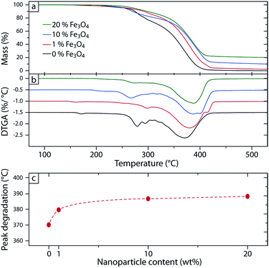
Fig. 3a and b shows the thermal degradation of the electrospun fibres under nitrogen and their derivative (DTGA). The mass remaining above 500 °C corresponded well to the nominal Fe3O4 contents with respect to the polymer in the electrospinning solutions, see Fig. 3a. The two peaks at approximately 280 and 380 °C were attributed to the two constituents of the polymer blend. This is consistent with the integrated DTGA areas of these two peaks, which correspond to the polymer composition, i.e. 75 wt% PMMA and 25 wt% PEO.Fig. 3c shows a 20 °C increase in thermal stability with increasing inorganic content, a common phenomenon seen in nanocomposites due to surface passivation during the degradation process.27,28 The passivation mechanism is in this case suggested to be due to the accumulation of inorganic filler at the surface of the molten sample when the initial evaporation of the matrix occurs, i.e. when the primary PEO degradation occurs (at the first peak in the DTGA) a layer/crust of inorganic material is formed on the surface, which retards the PMMA degradation.
Mechanical characterization
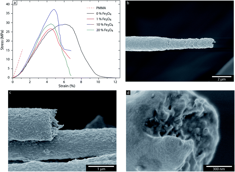
Strain–stress curves of all the materials studied are plotted in Fig. 4a, together with that of a brittle PMMA sample for comparison. The addition of 25 wt% PEO to the PMMA resulted in a dramatic increase (ca. 1500%) in the total work required to fracture the fibres, which made the mechanical properties of the composites directly dependent of the filler content. The fracture energy required to break the pristine PMMA fibres was 0.13 MJ m−3 compared to 2.14 MJ m−3 with 25% PEO. The addition of 10 wt% magnetite particles led to an increase in tensile strength (+41%) and in Young's modulus (+33%), but a decrease in the elongation at break (−41%), see Table 2. The toughness did not however change significantly, since the increase in strength compensated for the decreased in elongation at break. This reinforcement effect is due purely to the addition of the stronger and stiffer magnetite particles. A further addition of particles up to 20 wt% gave an elongation at break and modulus similar to the values achieved with 10 wt%, but with a lower strength (−31%) and lower toughness (−32%), suggesting that the particle dispersion or matrix adhesion was not as good with 20 wt% as with 10 wt%, also indicated by the large protrusions seen in Fig. 2g, h and j. The 1 wt% fibres had the lowest strength and modulus, see Table 2. This is explained by the slight fusing phenomenon seen in Fig. 2c and d, since the fibres are not completely solidified during collection. Overall, it was apparent that the addition of PEO to PMMA maintains large amounts of magnetite in the electrospun fibres while giving mechanical properties superior to those of the pristine PMMA. It is suggested that this is due to a strong interaction in the particle/matrix interface, suppressing the formation of voids/delamination, see Fig. 4b–d, which have previously been reported to occur in electrospun fibres and nanocomposites.29,30 The decrease in elongation at break with higher particle loading is interpreted as being due to different abilities of the fibres to allow fibre necking to occur, see Fig. 4b which shows the necking in the case of the pristine polymer blend. This necking phenomenon is gradually restricted with increasing particle content, see Fig. 4c and d.| Fe3O4 (wt%) | Strength (MPa) | Modulus (GPa) | Elongation (%) | Toughness (MJ m−3) |
|---|---|---|---|---|
| a Strength: maximum stress for the sample, modulus: calculated from the initial slope, elongation: value when stress reaches zero or when sample fractures, toughness: calculated from the total area under the stress–strain curve. | ||||
| 0 | 29.7 ± 3.1 | 0.85 ± 0.08 | 14.1 ± 4.1 | 2.14 ± 0.28 |
| 1 | 24.0 ± 3.9 | 0.75 ± 0.12 | 11.4 ± 2.1 | 1.82 ± 0.80 |
| 10 | 42.0 ± 5.5 | 1.13 ± 0.24 | 8.3 ± 3.0 | 2.15 ± 0.56 |
| 20 | 28.8 ± 6.2 | 1.12 ± 0.19 | 9.8 ± 2.2 | 1.47 ± 0.55 |
Magnetic characterization
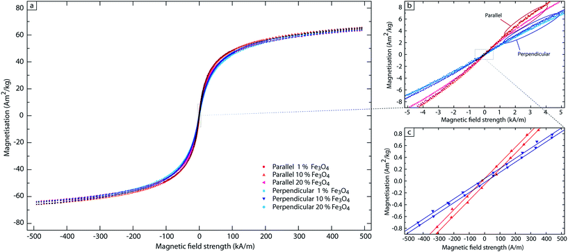
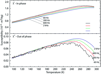
In order to determine the magnetization – the magnetic moment per weight of the magnetic material, which is an intrinsic property making a comparison meaningful – the weight of the magnetic fraction is required. The nominal fibre compositions are given in Table 1, but, since the solvent exchange process and further mixing may lead to a loss of some material, the results of the TGA experiments have been used to assess the inorganic (i.e. magnetite) content with greater confidence. The TGA measurements were conducted after the magnetic characterization on the same samples, thereby eliminating possible quantitative errors. The magnetic responses were characterized by being ‘Langevin-like’ with very small coercivity, which is often regarded as the signature of superparamagnetism, see Fig. 5. The concept of superparamagnetism, originally introduced by Neél and Brown, has as a prerequisite a vanishing coercivity when the particle size is below the critical material-dependent value.6 The idea is that thermal agitation, i.e. the ambient temperature, is sufficient to continuously alter the direction of magnetization of the magnetic entities.9,10 Therefore it is not strictly justifiable to claim superparamagnetism if a finite coercivity has been detected. Since it is in principle not possible to rule out an arbitrary small coercivity, the serious approach is to report an experimentally determined low value for the coercivity.Even so, a proof of superparamagnetism should also involve both time and temperature. One approach is the zero-field-cooled/field-cooled magnetization measurement, which determines the temperature (so called ‘blocking temperature’) where a randomly oriented but ferromagnetic material align with a (weak) external field upon heating due to that it becomes superparamagnetic. Prior to this magnetization vs. temperature measurement, the sample has been cooled without field, which in case of a superparamagnetic material render the sample, e.g. a collection of non-interacting particles magnetized in random directions, an average equal to zero. An extrapolation of this idea is to measure in- and out-of-phase AC susceptibility vs. temperature at different frequencies. When the material undergoes a transition from the ferro-/ferri- to the superparamagnetic state, a peak in both the in- and out-of-phase susceptibility is expected. The temperature at which the in-phase peaks is usually regarded as the blocking temperature, although the out-of-phase peak is often more distinct.31 This temperature is dependent on measurement time, which in case of AC susceptometry translates into reciprocal frequency. Higher frequency means a higher blocking temperature.32
In Fig. 6 we show an AC susceptibility measurement vs. temperature from 100 to 300 K at 4 frequencies (60–2 kHz), where the peak is shifted to higher temperature with increasing frequency (see ESI Fig. S3†). However, these approaches cannot rule out ferro-/ferrimagnetic impurities, whereas a test for coercivity is very sensitive for the detection of those and a low value ensures a small fraction. To make this reasoning more quantitative, the coercivity can be related to the field required to reach saturation. We suggest that a useful criterion is that the coercivity should be no greater than 1/1000 of the field required to reach 90% of the saturation magnetization. This field is commonly referred to as H90, and is also the point where the susceptibility has decreased to exactly 3% of its zero field value.33,34 Hence, by this practice a material is only superparamagnetic if the coercivity is less than H90/1000. However, in a plot showing ±90% of the magnetization, the two traces for increasing and decreasing field strengths will be indistinguishable at any meaningful line width.
To show the coercivity, a magnification of at least 100 is needed. This will help to make meaningful comparisons between reported data and eliminate those that are not entirely superparamagnetic.
In the present case the coercivity was ca. 20 A m−1 regardless of fibre orientation and magnetic content (below the 1/1000 coercivity criterion), see Fig. 5c. This value is very small, only about half of earths' field, and to our knowledge lower than any previously reported value. An important implication of this observation of a very minute coercivity is that ‘exchange interaction’ due to very close particle–particle distances is not effective since this would promote ferromagnetism and break the superparamagnetic behaviour. This in turn means that all individual nanoparticles are separated from each other by a distance of at least ca. 0.1–0.2 nm. In our polymer-based composite, the reasoning is that the polymer has encapsulated essentially all the particles, due to a strong adhesion at the polymer–particle interface visible in the fracture surfaces. The magnetization was also very similar for the different magnetite concentrations and different fibre orientations. At the maximum probed field of ±500 kA m−1, where the magnetization versus field response still has a considerable slope, the magnetization reached 64 A m2 kg−1, implying that the true saturation magnetization was distinctively higher. This result, that both the saturation magnetization (per weight of magnetic material) and the coercivity are independent of particle concentration and fibre orientation, is consistent with the view that the samples behave as ensembles of non-interacting superparamagnetic particles.
The mats were however distinctively easier to magnetize along the fibre axis rather than perpendicular to it, i.e. the mats showed a pronounced directional anisotropy of the susceptibility but without concentration dependence, see Fig. 5b. The susceptibility, which is the slope of the hysteresis loop at the origin, can also be derived theoretically, and the measured data can be compared with the theoretical. Paul Langevin, who first derived the dependence of the magnetization of non-interacting (super)paramagnetic entities on a magnetic field arrived at this expression over a hundred years ago:
which at low fields converges to:
where M and Msat are respectively the magnetization and saturation magnetization, μ0 is the permeability of vacuum (4π × 10−7 kg m C−2), μ is the magnetic moment of a single particle (μ = MsatV where V is the particle volume), H is the magnetic field, kB is the Boltzmann constant and T is the absolute temperature.34 This in turn means that the slope, i.e. susceptibility χ, of the plot of M versus H is equal to:
With Msat = 70 A m2 kg−1 (from measured rather than literature data), the density of magnetite 5200 kg m−3, the intrinsic susceptibility for cuboid particles with ca. 10 nm side length (from TEM micrographs) at room temperature (293 K) is χ = 14. According to magnetostatic theory, the measured susceptibility is always less than the intrinsic susceptibility due to a demagnetizing effect of the geometry and the orientation of the magnetic entities. In general, this demagnetizing effect is low in slender geometries magnetized along their long axis.7 Our samples were cylinder-shaped rolls of thin sheets oriented with their symmetry axis parallel to the magnetic field in the VSM, and this means that the magnetic field was always applied in the sheet planes, which has a very small demagnetizing effect. Therefore, the anisotropy was due only to whether the field was applied parallel to or perpendicular to the fibre axis. The measured values were χ = 12–13 for the parallel and χ = 8 for the perpendicular orientation with little or negligible dependence on the total particle concentration, Table 3. Therefore, we conclude that the magnetic material was arranged in elongated geometries with the long axis parallel to the fibre axis. The overall particle concentration had little effect on this anisotropy, suggesting that the size and shape of these elongated entities were independent of the particle concentration. This universal concentration independence means that it is probable that these entities existed already before the spinning event. This explanation for the anisotropy of susceptibility in combination with the absence of any sign of exchange interaction implies:
| Fe3O4 (wt%) | Fibre-orientation | HC (A m−1) | M*S (A m2 kg−1) | χmass (10−3 m3 kg−1) | χv (-) | |
|---|---|---|---|---|---|---|
| a HC: magnetic coercivity, M*S: magnetization @ 500 kA m−1 normalised with respect to the mass of Fe3O4, χmass: mass magnetic susceptibility at zero field, χv: volume susceptibility, χ∥/χ⊥: ratio of the susceptibility for the fibres aligned parallel and perpendicular to the applied field. | ||||||
| 1 | Parallel | 20.5 | 64.3 | 2.32 | 12.0 | 1.54 |
| 10 | Parallel | 19.5 | 65.8 | 2.60 | 13.5 | 1.54 |
| 20 | Parallel | 16.0 | 63.8 | 2.36 | 12.2 | 1.50 |
| 1 | Perpendicular | 19.0 | 63.9 | 1.51 | 7.8 | — |
| 10 | Perpendicular | 18.0 | 65.6 | 1.68 | 8.7 | — |
| 20 | Perpendicular | 16.5 | 63.5 | 1.58 | 8.2 | — |
(1) That the particles were separated from each other by at least a thin ca. 0.1–0.2 nm polymer layer so that exchange interaction is ineffective, and
(2) that the magnetic material appeared in elongated geometries with their long axis preferentially aligned along the fibre axis. Neither the orientation nor the size and shape were dependent on the total particle concentration.
Conclusions
Electrospun fibre mats of PMMA/PEO blends have been prepared with up to 20 wt% nanosized magnetite. The composite fibre mats showed no dependence on concentration or orientation of the magnetization or coercivity. Saturation magnetization was greater than 64 A m2 kg−1 (normalized with respect to magnetite) and the coercivity was extremely low, ca. 20 A m−1, consistent with superparamagnetism, which was further verified by AC susceptibility vs. temperature measurements at different frequencies. It is here suggested that a low measured coercivity (<1/1000) in relation to the field needed to reach 90% of saturation should be a useful criterion of superparamagnetism. A vanishing coercivity confirms the absence of a ferromagnetic impurity. This is a more stringent criterion, in line with Neél's definition, than e.g. the determination of the blocking temperature or a reference to particle size. It also makes it possible to compare results from different workers.The directional dependence of the low field susceptibility is explained by the magnetic material being geometrically aligned preferentially along the fibre axis. This directional dependence is independent of the total magnetic concentration.
The absence of any sign of exchange interaction (i.e. ultra-low coercivity) is explained by the individual particles being separated from each other by at least 0.1–0.2 nm, which suggests that the polymer encapsulate all the particles even if they appear in clusters.
The mechanical properties of the PMMA/PEO polymer material were essentially maintained with nanoparticle loading up to 20 wt%, which is presumably due to strong nanoparticle/polymer interaction and the absence of voids and delamination, further supported by the absence of exchange interaction/magnetic coercivity. Due to the good mechanical properties even at relatively high particle loadings, it is clear that the particle loading can be significantly increased to give even stronger magnetic functionality.
Acknowledgements
The authors acknowledge Prof KV Rao for the introduction into the fascinating world of magnetic materials and magnetic measurements. The financial aid provided by “Programa “José Castillejo” para estancias de movilidad en el extranjero de jóvenes doctors CAS14/00241” for Dr Cabedo's stay in Stockholm, Sweden, autumn 2014 is also acknowledged.Notes and references
- L. X. Tiefenauer, A. Tschirky, G. Kühne and R. Y. Andres, Magn. Reson. Imaging, 1996, 14, 391–402 CrossRef CAS PubMed.
- J. T. Mayo, C. Yavuz, S. Yean, L. Cong, H. Shipley, W. Yu, J. Falkner, A. Kan, M. Tomson and V. L. Colvin, Sci. Technol. Adv. Mater., 2007, 8, 71–75 CrossRef CAS.
- Q. A. Pankhurst, J. Connolly, S. K. Jones and J. Dobson, J. Phys. D: Appl. Phys., 2003, 36, R167 CrossRef CAS.
- S. Galland, R. L. Andersson, M. Salajkova, V. Strom, R. T. Olsson and L. A. Berglund, J. Mater. Chem. C, 2013, 1, 7963–7972 RSC.
- C.-L. Zhang and S.-H. Yu, Chem. Soc. Rev., 2014, 43, 4423–4448 RSC.
- D. J. Dunlop, J. Geophys. Res., 1973, 78, 1780–1793 CrossRef.
- B. D. Cullity and C. D. Graham, Introduction to magnetic materials, John Wiley & Sons, 2011 Search PubMed.
- G. F. Goya, T. S. Berquó, F. C. Fonseca and M. P. Morales, J. Appl. Phys., 2003, 94, 3520–3528 CrossRef CAS.
- L. Néel, Ann. Geophys., 1949, 5, 99–136 Search PubMed.
- W. F. Brown Jr, J. Appl. Phys., 1963, 34, 1319–1320 CrossRef.
- C. P. Bean and J. D. Livingston, J. Appl. Phys., 1959, 30, S120–S129 CrossRef.
- H. Althues, J. Henle and S. Kaskel, Chem. Soc. Rev., 2007, 36, 1454–1465 RSC.
- I. Greenfeld, K. Fezzaa, M. H. Rafailovich and E. Zussman, Macromolecules, 2012, 45, 3616–3626 CrossRef CAS.
- C. J. Goss, Phys. Chem. Miner., 1988, 16, 164–171 CrossRef CAS.
- V. Ström, R. T. Olsson and K. V. Rao, J. Mater. Chem., 2010, 20, 4168–4175 RSC.
- B. W. Ahn, M. H. Hahn and T. J. Kang, 18th Int.Conf. on composite mtrls, Korea, 2011 Search PubMed.
- Y. K. Sung, B. W. Ahn and T. J. Kang, J. Magn. Magn. Mater., 2012, 324, 916–922 CrossRef CAS.
- R. L. Andersson, M. Salajkova, P. E. Mallon, L. A. Berglund, M. S. Hedenqvist and R. T. Olsson, J. Polym. Environ., 2012, 20, 967–975 CrossRef CAS.
- F. Mei, S. Valter, T. O. Richard, B. Lyubov and K. V. Rao, Nanotechnology, 2012, 23, 145601 CrossRef PubMed.
- R. L. Andersson, A. Martínez-Abad, J. M. Lagaron, U. W. Gedde, P. E. Mallon, R. T. Olsson and M. S. Hedenqvist, Int. J. Mol. Sci., 2014, 15, 15912–15923 CrossRef CAS PubMed.
- R. L. Andersson, V. Ström, U. W. Gedde, P. E. Mallon, M. S. Hedenqvist and R. T. Olsson, Sci. Rep., 2014, 4, 6335 CrossRef PubMed.
- J. Khan, S. E. Harton, P. Akcora, B. C. Benicewicz and S. K. Kumar, Macromolecules, 2009, 42, 5741–5744 CrossRef CAS.
- P. J. Goodhew, J. Humphreys and R. Beanland, Electron microscopy and analysis, CRC Press, Third edn, 2000 Search PubMed.
- A. D. McNaught, IUPAC Compendium of Chemical Terminology: The Gold Book, International Union of Pure and Applied Chemistry, 2005 Search PubMed.
- I. N. Strain, Q. Wu, A. M. Pourrahimi, M. S. Hedenqvist, R. T. Olsson and R. L. Andersson, J. Mater. Chem. A, 2015, 3, 1632–1640 CAS.
- R. T. Olsson, R. Kraemer, A. Lopez-Rubio, S. Torres-Giner, M. Jose Ocio and J. Maria Lagaron, Macromolecules, 2010, 43, 4201–4209 CrossRef CAS.
- P. Visakh and O. B. Nazarenko, Thermal Degradation of Polymer Blends, Composites and Nanocomposites, Springer, 2015 Search PubMed.
- K. Chrissafis and D. Bikiaris, Thermochim. Acta, 2011, 523, 1–24 CrossRef CAS.
- D. Liu, A. M. Pourrahimi, R. T. Olsson, M. S. Hedenqvist and U. W. Gedde, Eur. Polym. J., 2015, 66, 67–77 CrossRef CAS.
- C.-L. Pai, M. C. Boyce and G. C. Rutledge, Macromolecules, 2009, 42, 2102–2114 CrossRef CAS.
- P. D. Allen, T. G. St Pierre, W. Chua-anusorn, V. Ström and K. V. Rao, Biochim. Biophys. Acta, Mol. Basis Dis., 2000, 1500, 186–196 CrossRef CAS.
- W. F. Brown, Phys. Rev., 1963, 130, 1677–1686 CrossRef.
- L. Tauxe, T. Mullender and T. Pick, J. Geophys. Res.: Solid Earth, 1996, 101, 571–583 CrossRef.
- P. Langevin, Ann. Chim. Phys., 1905, 5, 70–127 Search PubMed.
Footnote |
| † Electronic supplementary information (ESI) available: Fig. S1 to S3. See DOI: 10.1039/c5ra27791d |
| This journal is © The Royal Society of Chemistry 2016 |

