
Fabrication of monolithic carbon nanofiber/carbon composites†
Xiang Gea,
Mingqi Chena,
Jitong Wanga,
Donghui Longa,
Licheng Linga,
Wenming Qiao*ab,
Isao Mochidac and
Seong-Ho Yoon*c
aState Key Laboratory of Chemical Engineering, East China University of Science and Technology, Shanghai 200237, China. E-mail: qiaowm@ecust.edu.cn; Fax: +86-021-64252914; Tel: +86-021-64253730
bKey Laboratory of Specially Functional Polymeric Materials and Related Technology (East China University of Science and Technology), Ministry of Education, China
cInstitute for Materials Chemistry and Engineering, Kyushu University, 6-1 Kasuga Koen, Kasuga, Fukuoka, Japan. E-mail: yoon@cm.kyushu-u.ac.jp; Fax: +81-92-583-7879; Tel: +81-92-583-7959
First published on 11th January 2016
Abstract
Monolithic carbon nanofiber/carbon (M-CNF/C) composites were fabricated through facile liquid impregnation and hot pressing technologies, using monolithic carbon nanofibers and phenolic resin as reinforcement and carbon matrix precursor, respectively. The M-CNFs are uniformly dispersed in the M-CNF/C composites and display strong interfacial bonding with carbon matrix. Compared with powdered carbon nanofiber reinforced (P-CNF/C) composites, M-CNF/C composites exhibit significantly higher improvement in electrical conductivity, thermal conductivity and mechanical properties. The M-CNF/C composites also exhibit much lower friction coefficients (0.09–0.12) and wear losses (0.12–0.43 mg) than those of P-CNF/C composites. The superior enhancement is attributed to the unique 3D interconnected structure and high integrity of M-CNFs, which could dramatically increase conductive channels, significantly improve mechanical properties and remarkably decrease friction coefficient and wear loss of M-CNF/C composites. Furthermore, the electrical, thermal, mechanical and tribological properties of M-CNF/C composites could be adjusted by using M-CNFs with different bulk densities. The present work suggests the M-CNF/C composites a widespread potential as high-performance tribological materials.
1. Introduction
Carbon nanofibers (CNFs) are recognized as unique forms of carbon materials that are produced by the decomposition of selected hydrocarbons over metal particles.1–4 They have received an increasing academic and industrial interest due to their good mechanical properties, nice electrical characteristics, and high thermal performances.5–8 Compared with carbon fibers, CNFs display lower density, higher electrical conductivity as well as higher thermal conductivity.9–11 These novel properties make CNFs a promising candidate to fabricate advanced structural materials. Apart from being used in electronics, energy storage and catalyst supports,12–16 CNFs show potential applications in the form of reinforcement in polymers, ceramics, metals and carbon matrix,17–20 where they could improve mechanical and other functional properties.Recently, CNFs were used as fillers in composites in order to obtain good tribological properties.21–23 Being similar to carbon nanotubes and graphene, CNFs are expected to possess unique advantages in tribological applications due to their layered structures.24 The attractive characteristics of the layered structures could be summarized as follows:21–24 (i) remarkably improved mechanical properties of the composites with increased strength, yield points and fracture toughness, which could reduce the fatigue and failures resulting from brittleness; (ii) significantly superior thermal conductivity which can help dissipate the heat from friction, reducing plastic deformation and plasticity-induced damage of the composites; (iii) good solid lubrication capability due to graphitic structures (van der Waals forces between the layers and covalent bond within the graphitic planes) which could efficiently reduce friction coefficient and improve wear resistance of the composites. Therefore, the tribological materials reinforced by CNFs display remarkable improvement in mechanical, thermal and frictional performances.21–24
However, CNFs were generally synthesized in the form of nano-sized and fluffy powders, making their handling and large scale application difficult.1,2,25,26 As for application in composites, powdered CNFs (P-CNFs) reinforced composites only display moderate enhancement in many respects, including electrical, thermal and mechanical properties. Besides, P-CNFs tend to agglomerate when dispersed in matrix, resulting in nonuniformity and unstability of the composites.17 One promising way to solve the above problems is to introduce macroscopic CNFs, such as monoliths, foams, sponges and areogels, which could offer a great opportunity to develop high-performance composites.1,2,25,26 So far, very little attempt, to our knowledge, has been made to study the effect of macroscopic CNFs structures on the fabrication of macroscopic CNF/matrix composites. Also, there are no systematic studies on the properties, including electrical, thermal, mechanical and tribological behaviors of macroscopic CNF/matrix composites. Therefore, a study on the fabrication of macroscopic CNF/matrix composites as well as their structure and properties will provide a significantly important guideline to design distinguished high-performance composites for various applications.
In the previous work,1,2 our group reported a new kind of monolithic CNFs (M-CNFs) synthesized by one-step facile chemical vapour deposition (CVD). Such M-CNFs exhibit high porosity, controllable bulk density, high specific surface area and good mechanical properties. In the present work, inspired by the processing methods of carbon/carbon composites, the M-CNFs were used to fabricate monolithic carbon nanofiber/carbon (M-CNF/C) composites through liquid impregnation and hot pressing technologies. Such fabrication can avoid dispersion difficulty by impregnating carbon matrix precursor into the M-CNFs, thus process a unique advantage in producing M-CNF/C composite structures, in which CNFs are uniformly distributed in the matrix. The aim of this investigation is to explore the influence of the M-CNFs additions on the electrical, thermal, mechanical and tribological properties of M-CNF/C composites. Meanwhile, advantages of M-CNF/C composites could be evaluated by taking powdered carbon nanofiber/carbon (P-CNF/C) composites and carbon matrix with similar fabrication as a contrast.
2. Experimental
2.1 Synthesis of M-CNFs and P-CNFs
M-CNFs were synthesized by CVD, using C2H4 as carbon source and non-supported Ni–Cu alloy as catalyst.1,2 Specifically, catalysts were placed in a cylindrical quartz mold (Φ 25 × 50 mm) which was then put in the center of CVD furnace. Before introduction of carbon feedstock, the Ni–Cu alloy catalyst was reduced by a H2/He (1/4, v/v) mixture for 2 h at 580 °C. Then the C2H4/H2 mixture (4/1, v/v) was introduced and held at 580 °C for 1 h. After cooling, the CNF cylinder was removed from the mold. P-CNFs were synthesized by conventional CVD according to the literature reported elsewhere.272.2 Purification of M-CNFs and P-CNFs
The collected M-CNFs and P-CNFs were first cleaned by immersion in dilute nitric acid to eliminate the metal catalyst particles and amorphous carbon impurities.28 After a period of time, the M-CNFs and P-CNFs were then thoroughly rinsed in distilled water to remove acid and loosely attached particles. Finally, the M-CNFs were dried in a vacuum freeze drying cabinet while the P-CNFs were dried in a drying cabinet directly.2.3 Fabrication of M-CNF/C and P-CNF/C composites
The fabrication of M-CNF/C and P-CNF/C composites includes three cyclic steps: impregnation (dispersion), hot-pressing and carbonization. The total fabrication is schematically illustrated in Fig. 1. In the case of M-CNF/C composites, M-CNFs were impregnated with phenolic resin (PF)/alcohol solution at 1 MPa. After alcohol volatilized, the samples were placed in a mold and then hot-pressed at 180 °C under 150 MPa for 3 h. Subsequently, the samples were carbonized at 1000 °C (5 °C min) under nitrogen flow. Multiple impregnation, hot-pressing and carbonization were taken to densify the composites to the maximum density (Fig. S1†). For comparison, P-CNF/C composites and carbon matrix were prepared according to similar conditions, except for small changes. In the case of P-CNF/C composites, P-CNFs were dispersed in phenolic resin/alcohol solution by mechanical agitation (Fig. 1). As for carbon matrix, phenolic resin powers were hot-pressed directly. Multiple steps of impregnation, hot-pressing and carbonization of P-CNF/C composites and carbon matrix were taken for densification as well (Fig. S1†). The resultant M-CNF/C and P-CNF/C composites are indexed as M-CNF/C-x and P-CNF/C-x, respectively, where x represents the percentage (wt%) of M-CNFs or P-CNFs in the composites. | ||
| Fig. 1 Fabrication schematic of M-CNF/C and P-CNF/C composites. | ||
2.4 Characterization
The bulk densities of carbon matrix, P-CNF/C and M-CNF/C composites were determined by measuring the mass of a fixed volume.Morphologies of the samples were observed under scanning electron microscope (SEM; JOEL JSM3360LV) and transmission electron microscope (TEM; JOEL JSM2010).
X-ray diffraction (XRD) was performed on a Rigaku D/Max 2550VB/PC (Rigaku, Cu Kα radiation). Raman spectra were performed on a Raman microscope (InVia Reflex) with an excitation wavelength of 514.5 nm.
Electrical resistivity was measured using a four-point method at room temperature, and the electrical conductivity was calculated based on the electrical resistivity. Thermal conductivity was measured by flash method using the LFA 447 Nanoflash® (NETZSCH, Capitola, CA) at room temperature. Specimens with a dimension of Φ 12.7 × 3 mm were prepared from the center of the hot-pressed samples for the two measurements.
Compression test was performed on a universal testing machine (3367, Instron) with sample size of Φ 15 × 15 mm from the center of the hot-pressed samples, conducted at a loading speed of 1 mm min−1. Five samples were tested for each category to get an average value.
The friction test was performed on a ball-on-disk friction apparatus (GSM-Tribometer) at room temperature and ambient atmosphere. Friction occurred due to contact of the static ball and disk rotation by the motor (Fig. S2†). The test was performance under conditions of load: 5 N, sliding radius: 4.1 mm, sliding speed: 0.02, 0.05, 0.08, and 0.12 m s−1, relative humidity: 40% and test duration: 1 h. Before the test, samples were cleaned with acetone in a supersonic bath for 10 min. The wear loss was obtained by measuring the weight loss with a microbalance to detect weight changes as small as 10−5 g. Each experiment was repeated three times and the average values were expressed in the results. After the wear tests, the worn and un-worn surfaces of each sample were observed under SEM.
3. Results and discussion
3.1 Structural characteristics
The macro-morphology of P-CNFs shows a pile of fluffy powders (Fig. 2a), and SEM observation reveals that the fibers are separated with visible boundaries (Fig. 2b). In contrast, the M-CNFs exhibit macro-morphology of smooth and dense monolith with a dimension of Φ 25 × 50 mm (Fig. 2a). The microstructure of the M-CNFs (Fig. 2c) shows 3D interconnected networks due to high entanglement with the thick CNFs serving as the reinforcing rods while the thin coiled CNFs serving as the binding wires. Several CNFs grow from a catalyst particle leading to a unique branched structure (Fig. 2d) which enhances the entanglement of the fibers and finally benefits their strength as well as other performances.1,2 TEM image shows that both the P-CNFs and M-CNFs are of the herringbone type oriented at an angle with respect to the fiber axis (Fig. 2e and f). | ||
| Fig. 2 Morphologies of P-CNFs and M-CNFs: macro morphologies of P-CNFs and M-CNFs (a), SEM images of P-CNFs (b) and M-CNFs (c) (d), TEM images of P-CNFs (e) and M-CNFs (f). | ||
The P-CNFs and M-CNFs were then used to fabricate P-CNF/C and M-CNF/C composites, respectively. There is no obvious difference between the two kinds of composites from the macro morphologies (insets in Fig. 3a and b). However, significant differences could be observed under SEM from the fracture surfaces of the P-CNF/C and M-CNF/C composites. P-CNF/C composites show a rough fracture surface with clear sliding steps (Fig. 3a) whose formation strongly depends on CNF pull-out and CNF/matrix interface separation. In contrast, M-CNF/C composites give a relatively smooth fracture surface without obvious fracture steps, where M-CNFs are broken directly with carbon matrix rather than just pulled out of the matrix (Fig. 3b). The change of fracture behavior means the increase of the cohesion in M-CNF/C composites. TEM image shows obvious CNF pull-out and interface separation in P-CNF/C composites (Fig. 3c), which is in accordance with SEM observation. Nevertheless, M-CNFs are coated with carbon matrix and there is no sign of interface separation, indicating stronger interfacial bonding between CNFs and carbon matrix (Fig. 3d). The superior interfacial bonding is attributed to the 3D interconnected networks of M-CNFs with high integrity and uniformity in the composites (Fig. 1).
 | ||
| Fig. 3 Micro and macro morphologies of P-CNF/C composites (a), micro and macro morphologies of M-CNF/C composites (b), TEM image of P-CNF/C composites (c), TEM image of M-CNF/C composites (d). | ||
The density of M-CNFs is controllable through changing growth conditions such as growth time and catalyst amount.1,2 Therefore, a series of M-CNF/C composites with different CNF contents could be fabricated by using M-CNFs with different densities. As demonstrated in Table 1, the density of M-CNF/C composites gradually increases to the maximum at 33% of M-CNF content, and then decrease as M-CNF content increases. Such decrease of density could result from lower porosity of M-CNFs with higher density, which may increase diffusion barriers of impregnation.
| Samples | CNFs content (wt%) | M-CNFs density (mg cm−3) | M-CNFs porosity a (%) | Composite density (g cm−3) | Electrical conductivity (S cm−1) | Thermal conductivity (W m−1 K−1) |
|---|---|---|---|---|---|---|
| a Porosity was estimated based on calculations by using a density of 1.75.1,29 | ||||||
| Carbon matrix | — | — | — | 1.32 | 16.31 | 0.16 |
| P-CNF/C-22 | 22 | — | — | 1.61 | 29.24 | 0.64 |
| M-CNF/C-18 | 18 | 21.3 | 98.8 | 1.55 | 53.52 | 1.03 |
| M-CNF/C-22 | 22 | 50.9 | 97.1 | 1.63 | 79.39 | 1.21 |
| M-CNF/C-33 | 33 | 69.5 | 96.0 | 1.64 | 123.78 | 1.88 |
| M-CNF/C-40 | 40 | 110.3 | 93.7 | 1.58 | 154.24 | 2.04 |
Both P-CNF/C and M-CNF/C composites show a prominent reflection at ca. 26° and a weak peak at ca. 43° assigned to graphitic carbon (planes 002 and 100, respectively30) in XRD pattern (Fig. S3†). They both exhibit two bands at around 1600 cm−1 and 1350 cm−1 in Raman spectra (Fig. S4†), corresponding to the high crystalline graphite vibration in the tangential stretching mode and the disorder induced phonon mode.31 Although P-CNF/C and M-CNF/C composites exhibit higher graphitization than carbon matrix, resulting from the existence of CNFs, there is very little difference in XRD pattern or Raman spectra for the two composites (Fig. S3 and S4†).
3.2 Electrical and thermal properties
The electrical conductivity and thermal conductivity of C/C composites are important properties needed for some applications.32,33 CNFs have excellent electrical conductivity and thermal conductivity, which can give rise to higher electrical conductivity and thermal conductivity of C/C composites.34,35 Table 1 demonstrates the comparison of carbon matrix, P-CNF/C and M-CNF/C composites in electrical conductivity and thermal conductivity. Compared with carbon matrix, M-CNF/C-22 exhibits much higher improvement than P-CNF/C-22 in electrical conductivity and thermal conductivity. Even with a lower CNF content, the electrical conductivity and thermal conductivity of M-CNF/C-18 are pretty higher than that of P-CNF/C-22. The reason could be attributed to high integrity and continuity of M-CNFs, which can offer more continuous channels for electrical and thermal conduction. On the contrary, P-CNFs are individual and separated leading to limit increase of conductive channels. Additionally, it is observed that higher M-CNFs content is beneficial for improvement in electrical and thermal properties of M-CNF/C composites (Table 1). The electrical conductivity and thermal conductivity for M-CNF/C-33 and M-CNF/C-40 could increase by one order of magnitude compared with carbon matrix, respectively.3.3 Mechanical properties
Fig. 4a and b show the compressive stress–strain curves of carbon matrix, P-CNF/C and M-CNF/C composites. It is found that both P-CNFs and M-CNFs can improve compressive strength of carbon matrix. However, such improvement is strongly influenced by the structure of CNFs. P-CNF/C-22 composite only exhibits a moderate improvement of several times in compressive strength compared with carbon matrix (Fig. 3a). However, M-CNF/C-22 composite displays a remarkable improvement in compressive strength of more than 20 times compared with carbon matrix (Fig. 3b). Meanwhile, the M-CNF/C-22 can sustain much larger stain (up to 13%) than P-CNF/C-22 (6%) and carbon matrix (2%). In addition, the compressive modulus of M-CNF/C composites exhibit much higher than that of P-CNF/C composites and carbon matrix (Fig. 4c). The superior reinforcement of M-CNFs is due to the unique 3D interconnected structure with excellent integrity and uniformity in M-CNF/C composites, which results in considerable reinforcement in mechanical properties of M-CNF/C composites. Furthermore, it is important to note that the compressive strength and modulus of M-CNF/C composites could be controlled by changing the content of M-CNFs (the density of M-CNFs). As shown in Fig. 4b and c, compressive strength and modulus gradually increase to the maximum (ca. 128 MPa and 980 MPa, respectively) at 33% of M-CNFs, and then decrease as M-CNFs content increases. The decrease could result from lower porosity of M-CNFs (Table 1) which increases diffusion barriers of impregnation, and finally decreases interfacial bonding and mechanical properties. In spite of the CNFs content variations, the compressive strength and modulus of M-CNF/C composites are much higher than those of P-CNF/C composites, indicating the advantages of M-CNFs in the reinforcement. | ||
| Fig. 4 Compressive stress–strain curves of carbon matrix (a), P-CNF/C (a) and M-CNF/C composites (b), compressive modulus of carbon matrix, P-CNF/C and M-CNF/C composites (c). | ||
3.4 Tribological properties
Apart from the good performance in electrical, thermal and mechanical properties, the M-CNF/C display outstanding tribological performance as well. Fig. 5 shows the typical variations of the friction coefficient with respect to the sliding time of carbon matrix, P-CNF/C and M-CNF/C composites. All curves are typical oscillating curves, fluctuating around their average values, respectively. In the case of carbon matrix, the friction coefficient with respect to sliding time shows unstable behavior with sharp deflection and large amplitude of vibration. Although the friction coefficient of P-CNF/C and M-CNF/C composites fluctuate much less than carbon matrix during the test duration, M-CNF/C composites exhibit more stable friction performance. | ||
| Fig. 5 Variation of friction coefficient of carbon matrix, P-CNF/C and M-CNF/C composites with respect to sliding time performed at 0.12 m s−1. | ||
Fig. 6 shows the mean friction coefficient for carbon matrix, P-CNF/C and M-CNF/C composites during the friction test. The mean friction coefficient of carbon matrix exceeds 0.2, and that of P-CNF/C-22 is approximately 0.17. However, M-CNF/C composites show much lower values of approximately 0.09–0.12, and they display a concave type dependency as M-CNF content increases and give the lowest value at M-CNF/C-33. Interestingly, the mean friction coefficients of M-CNF/C composites are even superior to that of most C/C composites reported in the literature. As demonstrated in Table 2, they are much lower than that of chopped carbon fiber reinforced C/C composites,36,37 2D carbon cloth and felt reinforced C/C composites,38,39 3D needled carbon fiber reinforced C/C composites40–42 and special additive coated C/C composites.43,44 They are comparable to that of CNT-doped C/C composites,45 but slightly higher than that of CNT added C/C composites.46 Nevertheless, the fabrication process of M-CNF/C composites does not require modified reinforcement or a second reinforcement, which is much more facile than that of both CNT-doped and CNT added composites.
 | ||
| Fig. 6 Mean friction coefficients of carbon matrix, P-CNF/C and M-CNF/C composites performed at 0.12 m s−1. | ||
| Samples | Reinforcement | Friction coefficient | Ref. |
|---|---|---|---|
| C/C composite | Semi-random chopped PAN-based carbon fibers | 0.25–0.4 | 36 |
| PAN/phenolic-based C/C | Chopped PAN-based carbon fiber | 0.32–0.45 | 37 |
| 2D C/C composite | PAN-based carbon cloth | 0.27–0.55 | 38 |
| C/C composite | 2D PAN-based carbon fiber felt | 0.22–0.36 | 39 |
| C/C composite | 3D needled carbon fiber | 0.19–0.32 | 40 |
| C/C PAN-CVI | 3D needled carbon fiber | 0.26–0.38 | 41 |
| C/C composite | 3D ex-PAN fiber mat | 0.15–0.35 | 42 |
| MoSi impregnated C/C | MoSi, PAN-based carbon fiber | 0.25–0.62 | 43 |
| 2D C/C composite | Si nanoadditives, commercial 2D C/C | 0.22–0.62 | 44 |
| CNT-doped C/C | CNT, stacking carbon felt | 0.09–0.14 | 45 |
| CNT added C/C | CNT, carbon fiber | 0.08–0.11 | 46 |
| M-CNF/C composite | M-CNFs | 0.09–0.12 | This work |
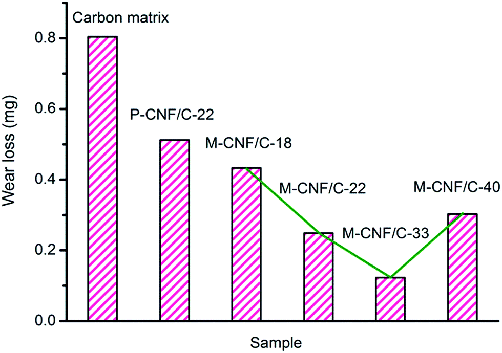
Fig. 7 shows the wear loss of carbon matrix, P-CNF/C and M-CNF/C composites during the friction test. Generally, the wear losses of M-CNF/C composites (0.12–0.43 mg) are much lower than that of carbon matrix and P-CNF/C composites. Additionally, M-CNF/C-33 shows the lowest wear loss of about 0.12 mg among the M-CNF/C composites as M-CNFs content increases. The mean friction coefficient and wear loss of M-CNF/C composites exhibit the lowest value at the same best M-CNFs content. Such low and controllable friction coefficients and wear loss indicate that the M-CNF/C composites are expected to be useful as new tribological materials.47
 | ||
| Fig. 7 Wear loss of carbon matrix, P-CNF/C and M-CNF/C composites performed at 0.12 m s−1. | ||
A high performance friction material should possess stable friction under varying operating speeds.47–49 The influence of sliding velocity on friction coefficient was studied at carbon matrix, P-CNF/C-22 and M-CNF/C-22 (Fig. 8). The friction coefficients of carbon matrix and P-CNF/C-22 show high dependence on sliding velocity, and give higher friction coefficient at higher sliding velocity. Nonetheless, the mean friction coefficient of M-CNF/C-22 shows almost no change when tested at different sliding velocities. It is interesting to note that the M-CNF/C composites display highly stable and low friction coefficient against sliding velocity conditions, which may further indicate the great potential of M-CNF/C composites as excellent tribological materials.
 | ||
| Fig. 8 The variation of mean friction coefficient with sliding velocity for carbon matrix, P-CNF/C and M-CNF/C composites. | ||
Friction coefficient and wear loss is closely related to the friction film which acts as a kind of lubricant.50–52 Fig. 9 shows SEM images of the border of the worn and unworn areas of carbon matrix, P-CNF/C and M-CNF/C composites. For carbon matrix, there are irregular and random pores on both of the original and worn surface, which could be the reason for the unstable friction behavior, high friction coefficient and high wear loss (Fig. 5). The worn surface of P-CNF/C composites is much smoother than M-CNF/C composites, indicating that P-CNF/C composites tend to be abraded more easily than M-CNF/C composites during the friction test. On the worn surface of M-CNF/C composites, there are some convex parts, which could result from the mixture of M-CNFs and carbon matrix. The convex parts indicate that the 3D interconnected networks of M-CNFs could make the M-CNF/C composites much more difficult to be abraded. The convex parts may further act as a solid lubricant when worn away from the surface.47 It is believed that the convex parts and worn particles produce film-like lubricity on the surface, which finally results in the low friction coefficient and wear loss of M-CNF/C composites.
 | ||
| Fig. 9 SEM images of the border of the worn and unworn areas of carbon matrix, P-CNF/C and M-CNF/C composites: (a) carbon matrix, (b) P-CNF/C-22, (c) M-CNF/C-18, (d) M-CNF/C-22, (e) M-CNF/C-33 and (f) M-CNF/C-40. | ||
4. Conclusion
M-CNF/C composites exhibit remarkable improvements in electrical conductivity, thermal conductivity, mechanical properties, while P-CNF/C composites only offer moderate ones. Significantly, M-CNF/C composites exhibit more stable friction behavior, much lower friction coefficient and wear loss than carbon matrix and P-CNF/C composites. The superior performances are attributed to the 3D interconnected networks of M-CNFs with excellent integrity and uniformity, which largely increase conductive channels, dramatically improve mechanical properties, and markedly reduce friction coefficient and wear loss. Furthermore, M-CNF/C composites show high stability with respect to sliding velocity while P-CNF/C composites are affected by sliding velocity. It is worth noting that the friction coefficients of M-CNF/C composites (ranging from 0.09–0.12) are much lower than those of most reported C/C composites. In addition, M-CNF/C composites show good controllability in electrical conductivity, thermal conductivity and compressive strength and modulus, and friction coefficient and wear loss by using M-CNFs with different densities. The present work suggests the great potential of M-CNF/C composites for application in tribological materials.Acknowledgements
This work was partly supported by MOST (2014CB239702), National Science Foundation of China (No. 51302083, No. U1303291, No. 51272077, No. 21506061), Fundamental Research Funds for the Central Universities and Shanghai Rising Star Program.Notes and references
- X. Ge, W. Yang, J. T. Wang, D. H. Long, L. C. Ling and W. M. Qiao, RSC Adv., 2015, 5, 70025–70031 RSC
.
- X. Ge, X. L. Wu, J. T. Wang, D. H. Long, W. M. Qiao and L. C. Ling, New Carbon Mater., 2015, 30, 54–62 Search PubMed
- S. H. Yoon, S. Lim, S. H. Hong, W. Qiao, D. D. Whitehurst, I. Mochida, B. An and K. Yokogawa, Carbon, 2005, 43, 1828–1838 CrossRef CAS
- N. M. Rodriguez, A. Chambers and R. T. K. Baker, Langmuir, 1995, 11, 3862–3866 CrossRef CAS
- D. Long, W. Li, J. Miyawaki, W. Qiao, L. Ling, I. Mochida and S. H. Yoon, Chem. Mater., 2011, 23, 4141–4148 CrossRef CAS
- J. F. Silvain, C. Vincent, J. M. Heintz and N. Chandra, Compos. Sci. Technol., 2009, 69, 2474–2484 CrossRef CAS
- G. Morales, M. I. Barrena, J. M. Gómez de Salazar, C. Merino and D. Rodríguez, Compos. Struct., 2010, 92, 1416–1422 CrossRef
- P. Li, T. J. Zhao, J. H. Zhou, Z. J. Sui, Y. C. Dai and W. K. Yuan, Carbon, 2005, 43, 2701–2710 CrossRef CAS
- M. H. Al-Saleh and U. Sundararaj, Carbon, 2009, 47, 2–22 CrossRef CAS
- M. Endo, Y. A. Kim, T. Hayashi, K. Nishimura, T. Matusita, K. Miyashita and M. S. Dresselhaus, Carbon, 2001, 39, 1287–1297 CrossRef CAS
- I. C. Finegan and G. G. Tibbetts, J. Mater. Res., 2001, 16, 1668–1674 CrossRef CAS
- D. Sebastián, I. Suelves, R. Moliner and M. J. Lázaro, Carbon, 2010, 48, 4421–4431 CrossRef
- R. Vellacheri, V. K. Pillai and S. Kurungot, Nanoscale, 2012, 4, 890–896 RSC
- Y. Shao, J. Liu, Y. Wang and Y. Lin, J. Mater. Chem., 2009, 19, 46–59 RSC
- M. Tsuji, M. Kubokawa, R. Yano, N. Miyamae, T. Tsuji, M. S. Jun, S. Hong, S. Lim, S. H. Yoon and I. Mochida, Langmuir, 2007, 23, 387–390 CrossRef CAS PubMed
- J. Ji, X. Duan, G. Qian, X. Zhou, D. Chen and W. Yuan, Ind. Eng. Chem. Res., 2013, 52, 1854–1858 CrossRef CAS
- F. L. Lou, Z. J. Sui, J. T. Sun, P. Li, D. Chen and X. G. Zhou, Mater. Lett., 2010, 64, 711–714 CrossRef CAS
- Q. Ngo, B. A. Cruden, A. M. Cassell, G. Sims, M. Meyyappan, J. Li and C. Y. Yang, Nano Lett., 2004, 4, 2403–2407 CrossRef CAS
- S. M. Jang, J. Miyawaki, M. Tsuji, I. Mochida and S. H. Yoon, Carbon, 2009, 47, 3383–3391 CrossRef CAS
- Q. M. Gong, Z. Li, X. W. Zhou, J. J. Wu, Y. Wang and J. Liang, Carbon, 2005, 43, 2426–2429 CrossRef CAS
- P. Werner, V. Altstädt, R. Jaskulka, O. Jacobs, J. K. Sandler, M. S. Shaffer and A. H. Windle, Wear, 2004, 257, 1006–1014 CrossRef CAS
- T. Larionova, T. Koltsova, Y. Fadin and O. Tolochko, Wear, 2014, 319, 118–122 CrossRef CAS
- P. Hvizdoš, V. Puchý, A. Duszová and J. Dusza, Scr. Mater., 2010, 63, 254–257 CrossRef
- G. Sui, W. H. Zhong, X. Ren, X. Q. Wang and X. P. Yang, Mater. Chem. Phys., 2009, 115, 404–412 CrossRef CAS
- M. K. van der Lee, A. J. van Dillen, J. W. Geus, K. P. de Jong and J. H. Bitter, Carbon, 2006, 44, 629–637 CrossRef CAS
- R. Vieira, C. Pham-Huu, N. Keller and M. J. Ledoux, Chem. Commun., 2002, 954–955 RSC
- C. M. Yoon, D. H. Long, S. M. Jang, W. M. Qiao, L. C. Ling, J. Miyawaki and S. H. Yoon, Carbon, 2011, 49, 96–105 CrossRef CAS
- S. P. Sharma and S. C. Lakkad, Surf. Coat. Technol., 2010, 205, 350–355 CrossRef CAS
- N. M. Rodriguez, J. Mater. Res., 1993, 8, 3233–3250 CrossRef CAS
- W. X. Chen, J. P. Tu, L. Y. Wang, H. Y. Gan, Z. D. Xu and X. B. Zhang, Carbon, 2003, 41, 215–222 CrossRef CAS
- A. G. Souza Filho, A. Jorio, G. G. Samsonidze, G. Dresselhaus, R. Saito and M. S. Dresselhaus, Nanotechnology, 2003, 14, 1130–1139 CrossRef CAS
- Z. Zhou, X. Wang, S. Faraji, P. D. Bradford, Q. Li and Y. Zhu, Carbon, 2014, 75, 307–313 CrossRef CAS
- G. Yuan, X. Li, Z. Dong, X. Xiong, B. Rand, Z. Cui and J. Wang, Carbon, 2014, 68, 413–425 CrossRef CAS
- J. F. Silvain, C. Vincent, J. M. Heintz and N. Chandra, Compos. Sci. Technol., 2009, 69, 2474–2484 CrossRef CAS
- Z. R. Ismagilov, A. E. Shalagina, O. Y. Podyacheva, A. V. Ischenko, L. S. Kibis, A. I. Boronin and E. N. Tkachev, Carbon, 2009, 47, 1922–1929 CrossRef CAS
- H. K. Shin, H. B. Lee and K. S. Kim, Carbon, 2001, 39, 959–970 CrossRef CAS
- H. H. Kuo, J. H. Chern Lin and C. P. Ju, Wear, 2005, 258, 1555–1561 CrossRef CAS
- R. Luo, X. Huai, J. Qu, H. Ding and S. Xu, Carbon, 2003, 41, 2693–2701 CrossRef CAS
- H. Deng, K. Li, H. Li, P. Wang, J. Xie and L. Zhang, Wear, 2010, 270, 95–103 CrossRef CAS
- X. Xiong, B. Huang, J. Li and H. Xu, Carbon, 2006, 44, 463–467 CrossRef CAS
- H. Kasem, S. Bonnamy, Y. Berthier and P. Jacquemard, Tribol. Int., 2010, 43, 1951–1959 CrossRef CAS
- H. Kasem, S. Bonnamy, Y. Berthier, P. Dufrénoy and P. Jacquemard, Wear, 2009, 267, 846–852 CrossRef CAS
- S. J. Park, M. K. Seo and J. R. Lee, Carbon, 2002, 40, 835–843 CrossRef CAS
- T. Policandriotes and P. Filip, Wear, 2011, 271, 2280–2289 CrossRef CAS
- Q. M. Gong, Z. Li, Z. Zhang, B. Wu, X. Zhou, Q. Z. Huang and J. Liang, Tribol. Int., 2006, 39, 937–944 CrossRef CAS
- D. S. Lim, J. W. An and H. J. Lee, Wear, 2002, 252, 512–517 CrossRef CAS
- M. Hokao, S. Hironaka, Y. Suda and Y. Yamamoto, Wear, 2000, 237, 54–62 CrossRef CAS
- P. Gopal, L. R. Dharani and F. D. Blum, Wear, 1995, 181–183, 913–921 CrossRef CAS
- Z. Wang, K. Dohda and Y. Haruyama, Wear, 2006, 260, 249–257 CrossRef CAS
- Y. J. Shi, F. Xin, H. Y. Wang and X. Lu, Wear, 2008, 264, 934–939 CrossRef CAS
- S. C. Moulzolf, R. J. Lad and P. J. Blau, Thin Solid Films, 1999, 347, 220–225 CrossRef CAS
- K. Miyoshi, Mater. Sci. Eng., A, 1996, 209, 38–53 CrossRef
Footnote |
| † Electronic supplementary information (ESI) available. See DOI: 10.1039/c5ra26049c |
| This journal is © The Royal Society of Chemistry 2016 |