Phase evolution and crystal growth of VO2 nanostructures under hydrothermal reactions

Weilai Yu , Shuai Li and Chi Huang*
College of Chemistry and Molecular Sciences, Wuhan University, Wuhan, 430072, China. E-mail: chihuang@whu.edu.cn

Received 12th November 2015 , Accepted 7th January 2016

First published on 12th January 2016


Abstract

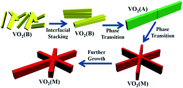
The phase evolution and crystal growth of VO2 nanostructures against reaction time in a high-pressure V2O5–oxalic acid hydrothermal system were systematically investigated. It was found that the rather thin VO2 (B) nanobelts were first obtained, then stacked to form large belt-like structures and subsequently phase transformed into VO2 (A), based on an oriented attachment-recrystallization mechanism. The large VO2 (A) belt-like structures could further assemble into novel “snowflake” VO2 (M) microcrystals with even bigger sizes and nearly well-defined six-fold symmetry. Due to the Ostwald ripening effect regarding crystal size discrepancy, the VO2 (M) phase could further grow at the cost of the gradual dissolution of VO2 (A) and full elimination of VO2 (B). The phase evolution from VO2 (B) first to VO2 (A) and then to VO2 (M), is actually a step-by-step thermodynamically downhill process, owing to the gradual relaxation of structural tension within the VO2 crystal lattice. Thus, our investigation, for the first time, demonstrated the feasibility of the well-known Ostwald's step rules towards the phase evolution process of VO2 and could provide unprecedented new insight to promote understanding of the synthesis and properties of vanadium oxide compounds.

1. Introduction

Due to its rich phase diagram with numerous non-hydrate polymorphs such as VO2 (M), VO2 (R), VO2 (A) and VO2 (B), vanadium dioxide (VO2) demonstrates unique electronic structures and diverse phase transition behaviour different from other binary transition metal oxides.1–3 During the past decade, vanadium dioxide has attracted tremendous research interests worldwide based on its great potentials for a wide range of practical applications, including cathode materials for lithium ion batteries, optical switches, smart window coatings, temperature-sensing devices and laser protection materials.2–7 In particular, the well-known metal-to-insulator transition (MIT) of VO2 has always been one of the scientific mysteries that researchers have attempted to fully address and illustrate.8 Upon heating to the critical temperature of 341 K, vanadium dioxide undergoes a fully reversible first-order phase transition from a low temperature monoclinic phase VO2 (M) to a high temperature tetragonal phase VO2 (R), accompanied by abrupt changes of optical and electrical properties.9–11 Although the underlying physical details of this phase transition process have not been completely understood at present, great advances have been achieved under extensive research efforts.12–20 For example, Tan et al. discovered dramatically decreased MIT critical temperatures induced by tungsten dopant atoms within VO2 crystal lattice, which can be attributed to the detwisting effect of the symmetric W core to lower the thermal energy barrier of phase transition.18 Moreover, Zhang et al. also found that the optical switching properties of VO2 can be effectively regulated by either W or Mo doping.19,20

Besides the metal-to-insulator transition of monoclinic phase vanadium dioxide VO2 (M), the syntheses and related properties of other polymorphs of VO2 such as VO2 (B) and VO2 (A) with different morphological structures have also drawn considerable attention.21,22 Among various approaches towards the syntheses of vanadium dioxide,22–25 hydrothermal synthesis was one of the most effective ways to synthesize nanoscale crystals with nearly uniform sizes and shapes.26–31 As well known, the reduction of V2O5 into VO2 under hydrothermal conditions by using appropriate amount of oxalic acid as reducing agent was one of the most classical systems that were investigated extensively.31,32 Usually, the VO2 (B) phase in the morphology of one-dimensional nanorod or nanobelt can be directly obtained under a normal hydrothermal pressure and soft reducing environment.26,32 However, very recently, our group discovered that the different additives into the above synthetic systems can perform catalytic functions to efficiently promote the formation of other VO2 polymorphs such as VO2 (A) and VO2 (M).33,34 This result is undoubtedly very intriguing since the direct phase transition from VO2 (B) into other VO2 polymorphs in the above hydrothermal system was rarely observed and achieved experimentally.

Herein, for the first time, we reported a direct investigation on the phase evolution and crystal growth of vanadium dioxide under an unusual high-pressure hydrothermal system without any other additives. Spontaneous phase evolution from VO2 (B) first into VO2 (A) and then to VO2 (M) with elongated reaction time was determined and the corresponding morphological changes between different VO2 phases were further observed and compared. Based on the phase structure analyses and morphological observations, the formation mechanism responsible for the phase evolution process of VO2 was tentatively presented and discussed. Furthermore, the feasibility of the well-known Ostwald's step rules towards the phase evolution of VO2 was demonstrated via the comparison of crystal structures of different VO2 polymorphs. This work will provide unprecedented new deep insights into the understanding of VO2 phase transition behaviour and promote further research on the synthesis and properties of vanadium oxide compounds.

2. Experimental

All reagents involved in experiments were of analytical grade and used without further purification. In a typical synthesis, 0.90 g V2O5 and 1.12 g oxalic acid dihydrate were dispersed in 80 ml deionized water under vigorous stirring at room temperature for 30 min. After the above mixture was uniformly dispersed in solution, the resulting suspension was then transferred to a 100 ml Teflon-lined stainless steel autoclave, which was sealed tightly and maintained at 180 °C for different reaction time (1 day to 7 days). Different samples were denoted as Vx, where x represented the reaction time that the Vx sample underwent. After the reaction was accomplished, the autoclave was cooled down to room temperature naturally and the products were collected by intense centrifugation. Deionized water and ethanol were used alternatively to wash the products three times in order to remove possible residues. The products were finally obtained after drying at 75 °C for more than 12 h. For the purpose of comparison, the same reactions were also performed in 60 ml deionized water for the same reaction times (1 day to 7 days), which is considered to generate a lower inner-pressure inside autoclave during VO2 formation compared with the former system with 80 ml deionized water.

X-ray diffraction (XRD) patterns were carried out on a D8 X-ray diffractometer under Cu Kα radiation at wavelength of 1.54060 Å to determine the phase structures of various samples. The scanning electron microscope (SEM) images were examined on JSM-6510 (JEOL, Japan) and JSM-7500F (JEOL, Japan) to probe the corresponding morphological changes of the V1–V7 samples. The transmission electron microscope (TEM) images, the high-resolution transmission electron microscope (HRTEM) analyses and the selected area electron diffraction (SAED) patterns were obtained on JEM-2100 (JEOL, Japan) equipped with a LaB6 emitter at acceleration voltage of 200 kV.

3. Results and discussions

XRD patterns were recorded in Fig. 1 to reveal the phase evolution progress of vanadium dioxide against reaction time. As shown in Fig. 1, V1 only exhibited characteristic diffraction peaks of VO2 (B) (PDF no. 81-2392, space group: C2/m, a = 12.09300 Å, b = 3.70210 Å, c = 6.4300 Å, β = 106.970°), suggesting that only the VO2 (B) phase could be obtained in the above V2O5–oxalic acid hydrothermal system if the reaction time was controlled in 1 day. This is consistent with other literature results that VO2 (B) typically serves as the major products in the above synthetic system.26 However, the XRD patterns of V2–V4 demonstrated other different diffraction peaks compared with V1, which should be attributed to the emergence of the new VO2 (A) phase (PDF no. 65-9786, space group: P42/ncm, a = 8.4336 Å, c = 7.6782 Å). This showed that by elongating the reaction time from 1 day to 2–4 days, VO2 (A) could also evolve besides the previous VO2 (B) under the above synthetic conditions. Meanwhile, the diffraction intensity of VO2 (A) phase gradually increased in contrast to VO2 (B), which indicated the further growth of the new VO2 (A) phase. Surprisingly, very limited amount of VO2 (M) (PDF no. 82-661, space group: P21/c, a = 5.75290 Å, b = 4.52630 Å, c = 5.38250 Å, β = 122.602°) could also be detected in XRD patterns of V2–V4, whose diffraction intensity was much weaker compared with either VO2 (B) or VO2 (A). However, the diffraction intensity of VO2 (M) did not undergo significant increase as VO2 (A) during 2–4 days. Interestingly, the XRD patterns of V5–V7 revealed that by further extending the reaction time to 5–7 days, the VO2 (B) phase, which originally served as the main product, completely disappeared and the diffraction intensity of VO2 (M) phase began to gradually increase relative to the preserved VO2 (A) phase.
image file: c5ra23898f-f1.tif
Fig. 1 XRD patterns of the obtained V1–V7 samples in diffraction angle (2θ) range of (a) 10° to 40° and (b) 40° to 60°; characteristic diffraction peaks of VO2 (B), VO2 (A) and VO2 (M) were denoted with black, red and blue dashed lines, respectively; the reference XRD patterns of VO2 (B), VO2 (A) and VO2 (M) with their corresponding PDF numbers were provided at the bottom of both (a) and (b); for clarity, the weak diffraction peaks of the limited VO2 (M) phase were only denoted in V2 sample with small red arrows.

On the other hand, the contrast experiments performed in only 60 ml deionized water showed that no other phases than VO2 (B) could be yielded even extending the reaction time from 1 day to 7 days in a relatively low pressure environment. The comparison of the obtained VO2 phases against reaction time in both high and low inner-pressure environments was shown in Table 1. Considering the different inner-pressures in these two systems, direct phase evolution of VO2 under hydrothermal conditions could only be achieved in a relatively high inner-pressure (80 ml/100 ml), whereas no obvious phase transition could be detected in a relatively low inner-pressure (60 ml/100 ml). Thus, higher inner-pressure inside autoclave is a deciding factor for direct phase evolution of VO2 by simply elongating the reaction time.

Table 1 Comparison of the obtained VO2 phases derived from high and low inner-pressure hydrothermal systems against reaction time
Reaction system Duration Major product
V2O5–oxalic acid in 80 ml deionized water 1 day VO2 (B)
2–4 days VO2 (B) + VO2 (A)
5–7 days VO2 (A) + VO2 (M)
V2O5–oxalic acid in 60 ml deionized water 1–7 days VO2 (B)


Since the products with 1 day reaction time in either high inner-pressure or low inner-pressure experiments were both only VO2 (B), the factor of inner-pressure had little influence on determining the phase structure of the 1 day product. The phase transition from VO2 (B) to VO2 (A) and VO2 (M) under hydrothermal condition still required more than 1 day to take place and accomplish. Also, it was likely that the emergence of VO2 (A) depended on the complete formation of VO2 (B) from V2O5, after which the VO2 (A) could then evolve and grow from VO2 (B). Based on the above analyses of XRD patterns, although very limited amount of VO2 (M) appeared simultaneously with VO2 (A), its intensity did not significantly increase despite the further growth of VO2 (A) from VO2 (B). In this regard, the emergence of limited VO2 (M) phase was attributed to the initial generation of VO2 (A) from VO2 (B) and its further growth could be largely inhibited by the incomplete phase evolution of VO2 (B) into VO2 (A). Similarly, the full elimination of VO2 (B) during 5–7 days again confirmed that the further growth of VO2 (M) relative to VO2 (A) relied on the complete transformation from VO2 (B) into VO2 (A). Thus, the whole phase evolution of VO2 actually occurred in a step-by-step manner. Specifically, VO2 (B) phase first formed from the hydrothermal reduction of V2O5, accompanied by the subsequent emergence of VO2 (A) and very limited VO2 (M). Then VO2 (A) underwent further growth until the full elimination of VO2 (B) phase. Eventually, the originally limited VO2 (M) phase started to undergo further growth from VO2 (A). Due to the fact the VO2 (B) is usually considered as the major product in the additive-free V2O5–oxalic acid hydrothermal system, this comprehensive discovery of direct phase evolution of VO2 (B) first into VO2 (A) and then to VO2 (M), which was rarely reported before, is undoubtedly intriguing. It might cast light on the one-step hydrothermal synthesis of VO2 (M) from V2O5–oxalic acid systems in the future research efforts.

SEM images were first used to investigate the microstructures and morphology of all the obtained V1–V7 samples. As seen in Fig. 2a and b, the synthesized V1 sample generally exhibited similar one-dimensional nanobelt morphology. Combined with the previous XRD patterns, these obtained nanobelts with length of 1–2 μm and width of 100–200 nm should be ascribed to VO2 (B), which is consistent with other literature reports.32 Also, these VO2 (B) nanobelts were observed to be rather thin in nature. The relatively high length-width ratio of the obtained VO2 (B) nanobelts indicated that the growing kinetics of the VO2 (B) phase differs in all three dimensions. Considering the similar shapes and sizes between the V1 sample and other reported VO2 (B) nanobelts, the relatively high inner-pressure of autoclave had limited effect over the morphology of the obtained VO2 (B) nanobelts in our experiments.32


image file: c5ra23898f-f2.tif
Fig. 2 (a) Low-magnification and (b) high-magnification SEM images of the V1 sample; SEM images of the V2 (c and d), V3 (e) and V4 (f) samples.

SEM images of the V2–V4 samples were also shown in Fig. 2c–f. Based on the above XRD patterns, the V2–V4 samples were supposed to be mainly hybrids of VO2 (B) and VO2 (A), besides the limited VO2 (M) phase. As reflected by Fig. 2c and d, the majority of V2 sample still consisted of rather thin nanobelts with high length-width ratio, which was very similar to the morphology of V1 sample. This similarity with the V1 sample suggested that the morphology of the previously obtained VO2 (B) nanobelts was partly preserved during the ongoing reaction process. Also, they continued to account for the VO2 (B) part in XRD patterns of the V2–V4 samples. However, these composed VO2 nanobelts also demonstrated a high tendency to stack with their interfaces and further form anomalous assembly structures shown in Fig. 2c and d. Similar anomalously assembled structures were also observed in the SEM images of V3 and V4, as shown in Fig. 2e and f. However, some other large belt-like structures with relatively high length-width ratio were also found in the V3 and V4 sample. Thus, it could be reasonably deduced that the aggregated assembly of thin VO2 (B) nanobelts could be an intermediate to achieve intimate interfacial stacking and then develop into large belt-like microstructures. Due to the original small sizes and high surface energy, the spontaneous stacking of these small VO2 (B) nanobelts could occur.35 Such compact assembly of VO2 (B) nanobelts could be further encouraged by the increasing reaction time and the inducing effect of high pressure. Also, the covalent interaction of the interfacial atoms among different nanobelts would occur to cause the subsequent fusion of small nanobelts into large belt-like structures. Since the V2–V4 samples were mainly hybrids of VO2 (B) and VO2 (A), the formation of such large belt-like structures should be closely related to the newly emerged VO2 (A) phase. Under the inducement of high pressure, the formation of interfacial covalent bonds could also assist the synergistic recrystallization to transform VO2 (B) into VO2 (A). In this regard, the formation of these large belt-like microstructures was based on an oriented attachment-recrystallization mechanism, in which the original VO2 (B) nanobelt building blocks first assembled into large belt-like structures and then recrystallized to evolve into VO2 (A).36,37 Notably, the VO2 (A) microrods with similar sizes and shapes were also synthesized in V2O5–oxalic acid hydrothermal system by other research groups and the same oriented attachment-recrystallization mechanism was adopted to explain their formation process.38–42

TEM images of the V3 sample were also obtained in order to provide clues to further support the above proposed oriented attachment-recrystallization mechanism. Consistent with the previous XRD patterns, both of the VO2 (B) and VO2 (A) phases could be found in the V3 sample. As shown in Fig. 3a and c, the irregular head part of the belt-like structures was composed of many densely packed individual small nanobelts. Interestingly, the selected area electron diffraction (SAED) pattern of the denoted head part, displayed in Fig. 3b, indicated that these aggregated nanobelt structures should be attributed to the VO2 (B) phase. Also, the SAED pattern of the head part also revealed the single crystalline nature of this irregular area, suggesting that the assembly of these small nanobelts actually occurred in an organized fashion. Moreover, the HRTEM analyses of the side part of the belt-like structure in Fig. 3d showed the interplanar crystal spacing of 0.351 nm, corresponding to the (110) lattice plane of VO2 (B). The HRTEM analyses, consistent with the above SAED pattern, indicated that not only the irregular head part but also the regular side part of the belt-like structure should be ascribed to VO2 (B). In this regard, the whole belt-like structure exhibited in Fig. 3a was an organized aggregate of VO2 (B) nanobelts. According to the above discussion of SEM images, the original small VO2 (B) nanobelts could first assemble into larger belt-like structures to achieve intimate interfacial stacking, driven by the high surface energy. Considering the single crystalline nature of the belt-like aggregates, it was again confirmed that such organized assembly of VO2 (B) nanobelts depended on an oriented attachment mechanism. Furthermore, these belt-like structures formed by the aggregation of small VO2 (B) nanobelts could be intermediates to eventually develop into VO2 (A) belt-like structures.


image file: c5ra23898f-f3.tif
Fig. 3 (a) Low-magnification TEM image of the typical VO2 (B) assembled belt-like structure; (b) SAED pattern of the denoted head part of VO2 (B) assembled belt-like structure; (c) high-magnification TEM image of VO2 (B) assembled belt-like structure; (d) HRTEM images of the denoted side part of VO2 (B) assembled belt-like structure; (e) TEM image and (f) HRTEM image of the VO2 (A) belt-like structure; inset of (e) is the corresponding SAED pattern of the denoted area.

Different from the above aggregate of VO2 (B) nanobelts, other belt-like structures with distinct crystal outlines were also found, as shown in Fig. 3e. Contrarily, the SAED pattern and HRTEM analysis of the denoted area in Fig. 3e revealed that the belt-like structure should be ascribed to the VO2 (A) phase.42 Interestingly, evident grain boundaries could also be identified within the VO2 (A) belt-like crystal, confirming that it was actually built from the assembly of smaller VO2 (B) nanobelt building blocks. The anomalous shape of the head part of the VO2 (A) belt-like structure and the existence of grain boundaries were due to the incompatible sizes of the smaller VO2 (B) nanobelts. Also, the regular crystal outlines and clear grain boundaries also suggested the fusion of small VO2 (B) nanobelts into the large VO2 (A) belt-like structures. Combined with the above discussion, the former VO2 (B) assembled belt-like structure was indeed an intermediate prior to the phase evolution from VO2 (B) to VO2 (A). Specifically, after achieving the intimate interfacial stacking, the original belt-like structure composed of individual VO2 (B) nanobelts could undergo synergistic recrystallization to evolve into these large VO2 (A) belt-like structures under the inducement of high inner-pressure. In this regard, the discovery of these two different belt-like structures in the V3 sample also strongly supported the oriented attachment-recrystallization mechanism proposed above.

As reflected by the above XRD patterns, the obtained V2–V4 samples then underwent further phase evolution into hybrids of VO2 (A) and VO2 (M) (V5–V7), accompanied by the full elimination of VO2 (B). The corresponding SEM images of the obtained V5–V7 samples were also demonstrated in Fig. 4a–e. As shown in Fig. 4a and b, novel “snowflake” microcrystals with even bigger sizes could be clearly identified in the field, while the above discovered one-dimensional VO2 (A) belt-like structures could also be found. A more careful observation of these novel “snowflake” microcrystals reveals that each of them was actually assembled by three pieces of belt-like structures whose extended length was around 10 μm. Moreover, these “snowflake” microcrystals generally exhibited nearly well-defined six-fold symmetry. Combined with the above XRD patterns, the emergence of these belt-assembled novel microcrystals is closely associated with the newly generated VO2 (M) phase. As shown in Fig. 4g and h, all of the TEM image, the HRTEM image and the SAED pattern were all obtained in order to further confirm the phase structure of these novel microcrystals. As expected, the analyses of HRTEM image and the SAED pattern both revealed that these novel “snowflake” microcrystals should be ascribed to the VO2 (M) phase. Considering the similar length and thickness between the composed belt-like structures and the previously discovered VO2 (A) belt-like structures, these novel “snowflake” microcrystals could firstly form by the organized assembly of VO2 (A) belt-like structures and then undergo full phase transition into VO2 (M). In this regard, the foregoing emergence of VO2 (A) belt-like structures plays a vital role in the final formation of these novel “snowflake” VO2 (M) microcrystals. Also, the high-pressure environment inside the autoclave could be critical for VO2 (A) to overcome the thermal energy barrier required for its transformation into VO2 (M). Similar “snowflake” microcrystals were also obtained by other researchers under comparable experimental conditions. These microcrystals were also formed by the assembly of the original belt-like structures and attributed to the VO2 (M) phase, thus lending strong support to the above point of view regarding the microcrystal formation.43


image file: c5ra23898f-f4.tif
Fig. 4 SEM images of the V5 (a and b), V6 (c) and V7 (d and e) sample; (f) TEM image of the “snowflake” VO2 (M) microcrystal. (g) HRTEM image and (h) SAED pattern of the denoted area of the VO2 (M) microcrystal in (f).

As the reaction proceeded, these novel VO2 (M) microcrystals in the V6 and V7 samples, shown in Fig. 4c–e, generally exhibited two characteristic features distinct from V5: (1) as reflected by Fig. 4c–e, the original well-defined six-fold symmetry in V5 was broken in the corresponding microcrystals of V6 and V7 by the crystal elongation in a specific direction and the randomly evolved matter around the crystal center; (2) Fig. 4d demonstrated that as the reaction went on, the composed belt-like structures in these microcrystals could also grow thicker compared with that of V5. A revisit to the previous XRD patterns revealed that the relative intensities of all diffraction peaks of VO2 (M) in contrast to VO2 (A) also gradually increased with elongated reaction time, indicating the further growth of VO2 (M) in contrast to VO2 (A). By combining the above two major features of morphological evolution with the changes of XRD patterns, it could be reasonably deduced that the above one-dimensional elongation, the newly formed matter evolved around the crystal center and the thickening of the composed belt-like structures were all attributed to the further growth of the VO2 (M) phase. Since the hydrothermal reactions generally involve the repeated processes of dissolution and recrystallization, the gradual decrease of VO2 (A) intensities in XRD patterns indicated that the crystal growth of the larger VO2 (M) microcrystals is due to the dissolution of relatively smaller VO2 (A) belt-like structures based on the well-known Ostwald ripening effect.44–47 Notably, the above obtained smaller VO2 (B) nanobelts also completely disappeared after 5 days, implying that the entire phase transition from VO2 (B) to VO2 (A) at this stage. In this regard, the emergence of VO2 (M) depended on both the complete formation of VO2 (A) and the full elimination of VO2 (B). Therefore, it was confirmed again that the whole phase evolution from VO2 (B) first to VO2 (A) and then to VO2 (M) actually took place in a step-by-step manner.

Contrast experiments were also performed in a lower inner-pressure environment and on the contrary, no significant morphological changes from the original VO2 (B) nanobelts were observed. Consistent with the results of XRD patterns, a high inner-pressure synthetic environment is critical for both the above phase evolution and the relevant morphological changes. Thus, we could briefly summarize the evolution progress of the vanadium dioxide in Fig. 5: when the V2O5 powder was reduced by an appropriate amount of oxalic acid under high inner-pressure hydrothermal conditions, the one-dimensional ultrathin VO2 (B) nanobelts first formed as in a low inner-pressure environment. As the reaction proceeded, the high inner-pressure could induce the subsequent stacking of the original VO2 (B) nanobelts to assemble into larger belt-like structures and then phase transformed into VO2 (A), based on an oriented attachment-recrystallization mechanism. These VO2 (A) belt-like structures could further assemble and evolve into novel “snowflake” VO2 (M) microcrystals with nearly six-fold symmetry whose extended diameter reached 10 μm. Eventually, due to the Ostwald ripening effect, the further growth of VO2 (M) generally occurred in the forms of one-dimensional elongation, random matter evolving and composed belt thickening, accompanied by the gradual dissolution of VO2 (A) and the full elimination of VO2 (B).


image file: c5ra23898f-f5.tif
Fig. 5 Schematic illustration of the morphological evolution mechanism for VO2 (B), VO2 (A) and VO2 (M).

In order to provide insight into the phase evolution process of VO2, the entire reaction process in our experiments from the perspective of crystal structures were also demonstrated in Fig. 6. According to the results from other research groups,48 among all VO2 polymorphs, the VO2 (B) phase is the least thermodynamically favorable phase with the lowest formation energy, while the VO2 (M) phase is the most thermodynamically favorable phase with the highest formation energy. Thus, other polymorphs like VO2 (A) generally serve as the intermediate phases between VO2 (B) and VO2 (M). A careful comparison of crystal structures can facilitate the understanding of the relative stability of VO2 (B), VO2 (A) and VO2 (M). As displayed by Fig. 6, the crystal structures of VO2 (B), VO2 (A) and VO2 (M) are all composed of VO6 octahedral basic units. In this regard, it is the different linking patterns of the composed VO6 octahedral units that determine the relative energy of these phases. In other words, how oxygen atoms covalently link to the surrounding vanadium atoms has a major influence over both the geometric and electronic structures and subsequently determines the relative energy of different VO2 phases. Initially, the VO2 (B) phase consists of two different kinds of oxygen atoms within its crystal lattice: two-coordinated bridge oxygen atoms and three-coordinated or four-coordinated oxygen atoms with nearly vertical V–O–V bond angles. According to the classical valence shell electron pair repulsion (VSEPR) theory, these nearly vertical V–O–V bonds can generate the most intense electronic repulsion and structural tension and thus are the least thermodynamically favorable. Furthermore, the VO2 (B) phase is well-known for its open framework structures with penetrating inner-tunnels within crystal lattice. The above oxygen atoms with nearly vertical V–O–V bond angles could be critical for the formation of these inner-tunnels by creating nonbonding domains that can connect into coherent channels. On the contrary, the generation of the open tunneled structures inside the VO2 (B) lattice actually produces significant structural tension contributed by the unfavorable vertical V–O–V bonds. Compared with VO2 (B), there are more two-coordinated bridge oxygen atoms with less electronic repulsion in VO2 (A), thus significantly reducing the structural tension. Moreover, the other four-coordinated oxygen atoms in VO2 (A) also expand their V–O–V bonds from the original vertical manner of VO2 (B). Accordingly, the opening degree of VO2 (A) crystal lattice also significantly decreases at the cost of V–O–V bond expansion. In this regard, the VO2 (A) phase with less structural tension is thermodynamically more stable relative to the VO2 (B) phase. Interestingly, the VO2 (M) phase is composed of uniform three-coordinated oxygen atoms with the V–O–V bond angles of nearly 120 degree. Within the VO2 (M) lattice, the intrinsically three-fold symmetric bonding manner of each oxygen atoms with the surrounding vanadium atoms is undoubtedly beneficial to evenly distribute the electron density in space and produces the least electronic repulsion. Therefore, the crystal structure of VO2 (M) is the most compact compared with VO2 (B) and VO2 (A), indicating the highest efficiency of spatial electron density distribution. Due to the least structural tension, the VO2 (M) phase is considered as the most stable phase in the whole VO2 polymorph family. It is worth mentioning that although the underlying details accounting for the organized assembly of VO2 (A) belt-like structures into the “snowflake” VO2 (M) microcrystals remained ambiguous, the nearly well-defined six-fold symmetry of the above novel VO2 (M) microcrystals could be related to the uniform three-fold symmetry of the V–O–V bonding manner within VO2 (M).


image file: c5ra23898f-f6.tif
Fig. 6 Schematic diagram of phase evolution route of VO2 polymorphs; grey and red balls represent vanadium and oxygen atoms, respectively.

Based on the above discussion regarding the relative stability among VO2 (B), VO2 (A) and VO2 (M), a general tendency for the VO2 phase evolution process is proposed: upon hydrothermal reduction of V2O5 to form VO2, the VO2 (B) that is the least thermodynamically favorable phase appeared at the very beginning and then underwent subsequent phase transition into VO2 (A). After the complete transformation from VO2 (B) into VO2 (A), VO2 (A) further evolved into VO2 (M), which is the most thermodynamically favorable phase among all VO2 polymorphs. This tendency accords well with the well-known Ostwald's step rules, which was put forward in 1897.49 As Ostwald put it, in general, it is the least thermodynamically stable polymorph that crystallizes first and then it will undergo a series of intermediate phases prior to the final formation of the most thermodynamically favorable structure.50–52 In our experiments, it was indeed the least thermodynamically favorable VO2 (B) phase that emerged first during reaction. Then, the VO2 (B) underwent phase transformation induced by the high inner-pressure into the VO2 (A), which served as an intermediate step. Eventually, the intermediate VO2 (A) phase further evolved into the most thermodynamically stable VO2 (M) phase. Also, as evidenced by our experiments, each advancement of VO2 into a new phase required the complete formation of the old one. Therefore, the whole VO2 phase evolution reaction is actually a step-by-step thermodynamically downhill process and can serve as another strong proof to the well-known Ostwald's step rules. To our knowledge, similar research concerning the comprehensive observation of phase evolution process of VO2 was rarely reported before. Based on the consensus that Ostwald's step rules are not universal laws but the possible tendency in nature, our results for the first time demonstrated that VO2 can also be ascribed to the compounds whose polymorph evolution progress agrees well with the prediction of Ostwald's step rules.

4. Conclusions

In summary, the phase evolution and crystal growth of VO2 nanostructures against reaction time in a high inner-pressure V2O5–oxalic acid hydrothermal system were successfully investigated. The rather thin VO2 (B) nanobelts first appeared and could then stack with their interfaces. Based on an oriented attachment-recrystallization mechanism, these small VO2 (B) nanobelts could assemble into large belt-like structures and then phase transformed into VO2 (A). These VO2 (A) belt-like structures could further assemble in an organized manner into even larger novel “snowflake” VO2 (M) microcrystals with nearly well-defined six-fold symmetry. Due to the Ostwald ripening effect, the further growth of VO2 (M) could be encouraged by the gradual dissolution of VO2 (A) and the full elimination of VO2 (B). The phase evolution process of VO2 is a step-by-step thermodynamically downhill process, accompanied by the gradual relaxation of structural tension within VO2 crystal lattice. The whole evolution route also accords well with the well-known Ostwald's step rules, in which the least thermodynamically favorable VO2 (B) phase emerged first, underwent an intermediate VO2 (A) phase and finally transformed into the most thermodynamically stable VO2 (M) phase. Thus, the feasibility of the Ostwald's step rules towards the phase evolution of VO2 was for the first time demonstrated. This work will provide unprecedented new insight into the synthesis and phase transition of vanadium oxide compound.

Acknowledgements

This work was supported by the National Natural Science Foundation of China (51572201) and the National Foundation for Cultivating Talents in Basic Sciences (J1103308).

References

  1. C. Wu, F. Feng and Y. Xie, Chem. Soc. Rev., 2013, 42, 5157–5183 RSC .
  2. L. Zhong, M. Li, H. Wang, Y. Luo, J. Pan and G. Li, CrystEngComm, 2015, 17, 5614–5619 RSC .
  3. (a) Y. Zhang, M. Fan, F. Niu, W. Wu, C. Huang, X. Liu, H. Li and X. Liu, Curr. Appl. Phys., 2012, 12, 875–879 CrossRef ; (b) W. Li, S. Ji, Y. Li, A. Huang, H. Luo and P. Jin, RSC Adv., 2014, 4, 13026 RSC .
  4. X. Liu, G. Xie, C. Huang, Q. Xu, Y. Zhang and Y. Luo, Mater. Lett., 2008, 62, 1878–1880 CrossRef CAS .
  5. C. Niu, J. Meng, C. Han, K. Zhao, M. Yan and L. Mai, Nano Lett., 2014, 14, 2873–2878 CrossRef CAS PubMed .
  6. L. Zhang, K. Zhao, W. Xu, J. Meng, L. He, Q. An, X. Xu, Y. Luo, T. Zhao and L. Mai, RSC Adv., 2014, 4, 33332–33337 RSC .
  7. (a) Y. Zhang, M. Fan, X. Liu, G. Xie, H. Li and C. Huang, Solid State Commun., 2012, 152, 253–256 CrossRef CAS ; (b) S.-D. Lan, C.-J. Chang, C.-F. Huang and J.-K. Chen, RSC Adv., 2015, 5, 73742–73751 RSC .
  8. X. Wang, Y. Cao, Y. Zhang, L. Yan and Y. Li, Appl. Surf. Sci., 2015, 344, 230–235 CrossRef CAS .
  9. M. Jiang, S. Bao, X. Cao, Y. Li, S. Li, H. Zhou, H. Luo and P. Jin, Ceram. Int., 2014, 40, 6331–6334 CrossRef CAS .
  10. K. Qian, S. Li, S. Ji, W. Li, Y. Li, R. Chen and P. Jin, Ceram. Int., 2014, 40, 14517–14521 CrossRef CAS .
  11. Y. Gao, C. Cao, L. Dai, H. Luo, M. Kanehira, Y. Ding and Z. L. Wang, Energy Environ. Sci., 2012, 5, 8708–8715 CAS .
  12. S. Fan, L. Fan, Q. Li, J. Liu and B. Ye, Appl. Surf. Sci., 2014, 321, 464–468 CrossRef CAS .
  13. Y. Zhang, J. Zhang, X. Zhang, S. Mo, W. Wu, F. Niu, Y. Zhong, X. Liu, C. Huang and X. Liu, J. Alloys Compd., 2013, 570, 104–113 CrossRef CAS .
  14. L. Whittaker, C. J. Patridge and S. Banerjee, J. Phys. Chem. Lett., 2011, 2, 745–758 CrossRef CAS .
  15. L. Whittaker, C. Jaye, Z. Fu, D. A. Fischer and S. Banerjee, J. Am. Chem. Soc., 2009, 131, 8884–8894 CrossRef CAS PubMed .
  16. Y. Zhang, M. Fan, W. Wu, L. Hu, J. Zhang, Y. Mao, C. Huang and X. Liu, Mater. Lett., 2012, 71, 127–130 CrossRef CAS .
  17. L. L. Fan, S. Chen, Z. L. Luo, Q. H. Liu, Y. F. Wu, L. Song, D. X. Ji, P. Wang, W. S. Chu, C. Gao, C. W. Zou and Z. Y. Wu, Nano Lett., 2014, 14, 4036–4043 CrossRef CAS PubMed .
  18. X. Tan, T. Yao, R. Long, Z. Sun, Y. Feng, H. Cheng, X. Yuan, W. Zhang, Q. Liu, C. Wu, Y. Xie and S. Wei, Sci. Rep., 2012, 2, 466 Search PubMed .
  19. Y. Zhang, W. Li, M. Fan, F. Zhang, J. Zhang, X. Liu, H. Zhang, C. Huang and H. Li, J. Alloys Compd., 2012, 544, 30–36 CrossRef CAS .
  20. Y. Zhang, X. Zhang, Y. Huang, C. Huang, F. Niu, C. Meng and X. Tan, Solid State Commun., 2014, 180, 24–27 CrossRef CAS .
  21. Y. Zhang, Y. Huang, J. Zhang, W. Wu, F. Niu, Y. Zhong, X. Liu, X. Liu and C. Huang, Mater. Res. Bull., 2012, 47, 1978–1986 CrossRef CAS .
  22. O. Monforta, T. Rochb, L. Satrapinskyyb, M. Gregorb, T. Plecenikb, A. Plecenikb and G. Plescha, Appl. Surf. Sci., 2014, 322, 21–27 CrossRef .
  23. Y.-K. Dou, J.-B. Li, M.-S. Cao, D.-Z. Su, F. Regman, J.-S. Zhang and H.-B. Jin, Appl. Surf. Sci., 2015, 345, 232–237 CrossRef CAS .
  24. J. Yoon, C. Park, S. Park, B. S. Mun and H. Ju, Appl. Surf. Sci., 2015, 353, 1082–1086 CrossRef CAS .
  25. R. Minch and M. Es-Souni, CrystEngComm, 2013, 15, 6645 RSC .
  26. N. Li, W. Huang, Q. Shi, Y. Zhang and L. Song, Ceram. Int., 2013, 39, 6199–6206 CrossRef CAS .
  27. W. Lv, D. Huang, Y. Chen, Q. Qiu and Z. Luo, Ceram. Int., 2014, 40, 12661–12668 CrossRef CAS .
  28. I. Mjejri, N. Etteyeb and F. Sediri, Ceram. Int., 2014, 40, 1387–1397 CrossRef CAS .
  29. Y. Zhang, C. Chen, W. Wu, F. Niu, X. Liu, Y. Zhong, Y. Cao, X. Liu and C. Huang, Ceram. Int., 2013, 39, 129–141 CrossRef CAS .
  30. M. Li, F. Kong, Y. Zhang and G. Li, CrystEngComm, 2011, 13, 2204–2207 RSC .
  31. W. Jiang, J. Ni, K. Yu and Z. Zhu, Appl. Surf. Sci., 2011, 257, 3253–3258 CrossRef CAS .
  32. X. Xiao, H. Cheng, G. Dong, Y. Yu, L. Chen, L. Miao and G. Xu, CrystEngComm, 2013, 15, 1095–1106 RSC .
  33. Y. Zhang, J. Zhang, X. Zhang, Y. Deng, Y. Zhong, C. Huang, X. Liu, X. Liu and S. Mo, Ceram. Int., 2013, 39, 8363–8376 CrossRef CAS .
  34. Y. Zhang, J. Zhang, X. Zhang, C. Huang, Y. Zhong and Y. Deng, Mater. Lett., 2013, 92, 61–64 CrossRef CAS .
  35. W. Lv, W. He, X. Wang, Y. Niu, H. Cao, J. H. Dickerson and Z. Wang, Nanoscale, 2014, 6, 2531–2547 RSC .
  36. J. Zhang, F. Huang and Z. Lin, Nanoscale, 2010, 2, 18–34 RSC .
  37. R. L. Penn and J. F. Banfield, Science, 1998, 281, 969–971 CrossRef CAS PubMed .
  38. P. Liu, K. Zhu, Y. Gao, Q. Wu, J. Liu, J. Qiu, Q. Gu and H. Zheng, CrystEngComm, 2013, 15, 2753–2760 RSC .
  39. L. Li, P. Liu, K. Zhu, J. Wang, J. Liu and J. Qiu, J. Mater. Chem. A, 2015, 3, 9385–9389 CAS .
  40. S. Rao Popuri, A. Artemenko, C. Labrugere, M. Miclau, A. Villesuzanne and M. Pollet, J. Solid State Chem., 2014, 213, 79–86 CrossRef CAS .
  41. L. Dai, Y. Gao, C. Cao, Z. Chen, H. Luo, M. Kanehira, J. Jin and Y. Liu, RSC Adv., 2012, 2, 5265–5270 RSC .
  42. J. Hou, J. Zhang, Z. Wang, Z. Zhang and Z. Ding, RSC Adv., 2014, 4, 18055 RSC .
  43. C. Cao, Y. Gao and H. Luo, J. Phys. Chem. C, 2008, 112, 18810–18814 CAS .
  44. C. C. Yec and H. C. Zeng, J. Mater. Chem. A, 2014, 2, 4843–4851 CAS .
  45. P. Dagtepe and V. Chikan, J. Mater. Chem. C, 2010, 114, 16263–16269 CAS .
  46. S. T. Gentry, S. F. Kendra and M. W. Bezpalko, J. Mater. Chem. C, 2011, 115, 12736–12741 CAS .
  47. R. Zong, X. Wang, S. Shi and Y. Zhu, Phys. Chem. Chem. Phys., 2014, 16, 4236–4241 RSC .
  48. C. Wu, F. Feng, J. Feng, J. Dai, J. Yang and Y. Xie, J. Mater. Chem. C, 2011, 115, 791–799 CAS .
  49. W. Ostwald, Z. Phys. Chem., 1897, 22, 289–330 CAS .
  50. N. Niekawa and M. Kitamura, CrystEngComm, 2013, 15, 6932 RSC .
  51. R. A. Van Santen, J. Phys. Chem., 1984, 88, 5768–5769 CrossRef CAS .
  52. A. L. Washington, M. E. Foley, S. Cheong, L. Quffa, C. J. Breshike, J. Watt, R. D. Tilley and G. F. Strouse, J. Am. Chem. Soc., 2012, 134, 17046–17052 CrossRef CAS PubMed .

Footnote

These authors contributed equally to this work.

This journal is © The Royal Society of Chemistry 2016