
Simple preparation of Cu6Sn5/Sn composites as anode materials for lithium-ion batteries†
QiGang Han*ab,
Zheng Yiab,
Yong Chengb,
Yaoming Wub and
LiMin Wang*b
aRoll-forging Research Institute and College of Materials Science and Engineering, Jilin University, Changchun 130025, China. E-mail: hanqg@jlu.edu.cn; Fax: +86 431 85094340; Tel: +86 431 85094340
bState Key Laboratory of Rare Earth Resource Utilization, Changchun Institute of Applied Chemistry, CAS, Changchun 130022, China. E-mail: lmwang@ciac.ac.cn; Fax: +86 431 85262447; Tel: +86 431 85262447
First published on 1st February 2016
Abstract
Cu6Sn5/Sn composites are directly fabricated by a high energy mechanical milling technique and subsequent heat treatment. In particular, the effects of the ratios of Sn to Cu6Sn5 (CuxSny, x = 10 − y, y = 4.5, 7 and 9) on the lithium-ion batteries performances are investigated. The results show that the sample with y = 4.5 is a single-phase Cu6Sn5, the sample with y = 7 is slightly Sn rich in the Cu6Sn5 (Sn < Cu6Sn5), and the sample with y = 9 is excessively Sn rich in the Cu6Sn5 (Sn > Cu6Sn5). Furthermore, the Cu6Sn5/Sn composite has an obvious structure of a core–shell, only when y = 7. As an anode material for lithium-ion batteries, the Cu6Sn5/Sn composite with y = 7 exhibits a discharge capacity of 761.6 mA h g−1 after the first cycle, 457.8 mA h g−1 after 20th cycles, and an initial coulombic efficiency of 91.37%, which shows a better electrochemical performance than that of y = 4.5 or 9. In addition, after adding 15 wt% of graphite, the sample with y = 7 maintains a discharge capacity of 605.8 mA h g−1 after 100 repeated cycles, higher than many reported Cu–Sn-based anode materials.
1. Introduction
Currently, a mountain of research has been focused on developing alternative anode materials with higher energy density than commercial graphite.1–3 Among them, tin-based materials have been regarded as one of the most promising alternative anode materials for lithium-ion batteries (LIBs) due to the high theoretical capacity, low potential of lithium-ion intercalation, and low price.4–6 Unfortunately, the use of pure tin (Sn) as an anode material is limited because of its significant volume change during the lithiation and delithiation processes. This leads to electronic isolation of the lithiated product and poor electrical contact with the current collector. Besides, LixSn (x ≤ 4.4) alloys are brittle and pulverized easily by large Li-driven volume variation during the charge and discharge reactions.In order to overcome the volume fluctuation, a promising approach is to distribute the Sn inside a matrix of Li-inactive phase (denote as M) and form MxSny intermetallic compounds. Various MxSny alloys, such as Cu6Sn5, CoSn2, Ni3Sn4 and FeSn2, etc., have been studied as candidate anode materials for LIBs.7–11 The results indicate that the MxSny electrode can provide a much more stable cycling performance than pure Sn electrode. In addition, the Cu6Sn5 intermetallic compound has been considered as the most promising alternative anode material because it is easy to be synthesized, stable in an air environment, and reversible two-phase lithium insertion/extraction between Cu6Sn5 and Li2CuSn. Furthermore, the Cu6Sn5 intermetallic can encase the lithium/tin alloy in a conductive copper matrix. All of the advantages endow the Cu6Sn5 intermetallic with good lithium storage performances. For instance, the Cu6Sn5 alloy firstly prepared by Kepler et al. in 1999 showed a discharge capacity of ∼200 mA h g−1 after 20 cycles.7 Then, He et al. prepared the Cu–Sn alloy by electrodeposition along with a heat-treatment, where the uncoated Cu–Sn alloy delivered a discharge capacity of 428 mA h g−1 after 15 cycles while the Cu-coated one maintained 220 mA h g−1 after 50 cycles.12 Single-bath, pulsed electrodeposition of Cu–Sn alloy film was performed by Beattie et al.13 Their sample exhibited a reversible capacity of ∼200 mA h g−1 after 40 cycles at a current density of 15 mA g−1. By electron-beam deposition, Hu et al. prepared the Sn/Cu6Sn5 alloy composite thin film with a discharge capacity of ∼370 mA h g−1 after 50 cycles.14
On one hand, it is well known that the Cu content in the Cu–Sn alloy is increased; the specific capacity is sacrificed for capacity retention. Hence, the additive proportion of Sn is the key factor that affects the performance of Cu–Sn alloy for LIBs, but few studies have explored the effects of ratios of Sn to Cu6Sn5 on the performances for LIBs. On the other hand, the mechanical milling technique method has many unique advantages in comparison with other routes like the solution method. Firstly, the finished product yield close to almost 100% can be obtained when used the mechanical milling technique, while the solution method usually gains a low value. Secondly, the component of the materials can be easily controlled by adding the raw materials at a designed ratio before milling. Moreover, compared with the solution method, the mechanical milling technique is cost-effective and connecting with the actual production process. Therefore, in this work, we directly fabricate the Cu6Sn5/Sn composites with different ratios of Cu6Sn5 to Sn by the high energy mechanical milling technique. Then, the electrochemical lithium storage performances of the Cu6Sn5/Sn composites as anode materials for LIBs are investigated. To further enhance the cycling performances, the obtained Cu6Sn5/Sn composite with y = 7 is reprocessed by adding graphite into. Our synthetic route described herein is a simple, low-cost, and large-scale method to produce the high-performance Sn anode material, presenting a promising prospect for practical application.
2. Experimental
The pure metal powders Cu and Sn (>99.99%) were mixed by the atom ratio of Cu![[thin space (1/6-em)]](https://www.rsc.org/images/entities/char_2009.gif) :Sn = x:y, where x = 10 − y, y = 4.5, 7 and 9. Then, the Cu6Sn5/Sn composites (CuxSny) were prepared by the high energy mechanical ball milling technique (SPEX8000D), with the total time of 400 min and an argon atmosphere. In order to avoid the super-heating which cause by the continuous working, the rest of 20 min was set every internal of 40 min. After mechanical milling, a heat treatment with 150 °C for 400 min was performed on the mixture powders, whose aim was to achieve a phase of alloy. The X-ray diffraction (XRD) was used for making the contrast of the different phase of the samples, scanning electron microscope (SEM) was used for observing micro-morphology, high-resolution transmission electron microscope (HRTEM) and energy-dispersive X-ray (EDX) were used for observing the Cu6Sn5/Sn core–shell structure.
:Sn = x:y, where x = 10 − y, y = 4.5, 7 and 9. Then, the Cu6Sn5/Sn composites (CuxSny) were prepared by the high energy mechanical ball milling technique (SPEX8000D), with the total time of 400 min and an argon atmosphere. In order to avoid the super-heating which cause by the continuous working, the rest of 20 min was set every internal of 40 min. After mechanical milling, a heat treatment with 150 °C for 400 min was performed on the mixture powders, whose aim was to achieve a phase of alloy. The X-ray diffraction (XRD) was used for making the contrast of the different phase of the samples, scanning electron microscope (SEM) was used for observing micro-morphology, high-resolution transmission electron microscope (HRTEM) and energy-dispersive X-ray (EDX) were used for observing the Cu6Sn5/Sn core–shell structure.
The working electrode was prepared by compressing a mixture of the active material (CuxSny), acetylene black, and polyvinylidene fluoride (PVDF) with a weight ratio of 80:10:10 (mixed with a suitable N-methyl-pyrrolidone solvent) onto a copper foil (12 mm in diameter) and drying in a vacuum oven at 60 °C for 12 h. Then, the cells were assembled in a glovebox filled with highly pure argon gas. The electrochemical measurements were carried out by using CR 2025 coin-type cells with pure lithium as the counter electrode, a Celgard 2400 membrane as the separator, and 1 M LiPF6 dissolved in ethylene carbonate (EC) and dimethyl carbonate (DMC) with a volume ratio of 1:1 as the electrolyte. The cyclic voltammogram was conducted on a BioLogic VMP3 electrochemical workstation. The charge and discharge performances were tested between 0.01 V and 2.0 V using a programmable battery testing system (LAND CT2001A) at room temperature.
3. Results and discussion
Fig. 1 shows the XRD patterns of the CuxSny (x = 10 − y, y = 4.5, 7 and 9) alloys. The peaks at 30.2°, 35.2°, 43.2° and 43.5° are indexed to single-phase Cu6Sn5, when y = 4.5. However, the peaks are indexed to both Sn and Cu6Sn5 phases, when y = 7 or 9. Notedly, the characteristic peaks of Cu6Sn5 are weaker than that of Sn, which shows the sample with y = 9 has excessively Sn rich in the Cu6Sn5 (Sn > Cu6Sn5). However, as a vivid contrast, the characteristic peaks of Cu6Sn5 are rather strong than that of Sn, suggesting the sample with y = 7 with slightly Sn rich in the Cu6Sn5 (Sn < Cu6Sn5). The peaks at 29.9° and 33.3° were indexed to SnO phase, which may be formed in the process of high energy mechanical milling. In addition, the sample with y = 7 prepared in different ball-milling times shows time-dependent phase evolution. As shown in Fig. S1 (ESI†), the intensity of Cu6Sn5 phase increases as the prolonging of ball milling time within 400 min. However, although the time increased to 600 min, it is nearly the same as the ball milling time with 400 min. It can be seen that the phase composition of the sample is steady after the sufficient ball milling times. Hence, we design the samples with limited ball milling time of 400 min. | ||
| Fig. 1 The XRD patterns of the CuxSny (x = 10 − y, y = 4.5, 7 and 9) alloys. (a) The sample with y = 4.5, (b) the sample with y = 7, and (c) the sample with y = 9. | ||
Fig. 2 presents the SEM and HRTEM images of the CuxSny (x = 10 − y, y = 4.5, 7 and 9) alloys. It could be seen that the particles distribution with sizes of several decades' nanometers. There is not obviously difference of the primary particles size in the obtained samples. To further confirm the structure characterization of the as-synthesized CuxSny alloys, the HRTEM images are obtained (Fig. 2d–f). It is observed that a Sn layer is deposited onto the Cu6Sn5 particle when y = 7. However, no core–shell particles are founded when y = 4.5 or 9. The lattice fringes can be clearly seen in the HRTEM images, in which the 0.209 and 0.296 nm can be assigned to the (110) and (101) interplane spacing of Cu6Sn5, and the 0.292 and 0.279 nm can be assigned to the (200) and (101) interplane spacing of Sn.
 | ||
| Fig. 2 The SEM and HRTEM images of the CuxSny (x = 10 − y, y = 4.5, 7 and 9) alloys. (a) The SEM image of sample with y = 4.5, (b) the SEM image of sample with y = 7, (c) the SEM image of sample with y = 9, (d) the HRTEM image of sample with y = 4.5, (e) the HRTEM image of sample with y = 7, and (f) the HRTEM image of sample with y = 9. | ||
In order to provide further insight into the structure information on the characterization of core–shell, an EDX line-scan analysis of Cu and Sn along the scan-path is shown in Fig. 3. It indicates that there is no clear difference of the Sn content along the scan-path. However, an obviously changes of the Cu content along the scan-path is observed when y = 7. A lesser Cu content in the two sides of the scan-path and a higher Cu content in the center of the scan-path are obtained, indicating a core–shell structure possessed by the sample with y = 7. According to the contents, the components of core and shell are distinguished as Cu6Sn5 and Sn, respectively. The Sn layers are homogeneously deposited onto the Cu6Sn5 particles, indicating that Cu6Sn5 can serve as a stable support for Sn alloy, which are originated from the slightly Sn rich in the Cu6Sn5 (Sn < Cu6Sn5).
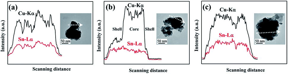 | ||
| Fig. 3 The EDX line-scanning profile of Cu and Sn along the scan-path for (a) the sample with y = 4.5, (b) the sample with y = 7, and (c) the sample with y = 9. | ||
To simply understand the formation process of the core–shell structure, a schematic diagram is given as shown in Fig. S2 (ESI†). The power derived from the ball milling is the driving force for the formation of Sn shell over Cu6Sn5. With y = 7, due to the thin Sn film over Cu6Sn5 core, this core–shell structure can be maintained, although the following ball milling continued. However, with y = 9, because of the superfluous Sn film over Cu6Sn5 core, this core–shell structure can be turned into numerous small core–shell, namely, numerous Cu6Sn5 core diffused into the Sn matrix.
Fig. 4 shows the CV curves in the initial three cycles of CuxSny (x = 10 − y, y = 4.5, 7 and 9) alloys electrodes with potential sweep rate of 0.2 mV s−1. A cathodic current peak is appeared around 0.8 V in the first cycle when y = 4.5, which corresponds to the decomposition of solvent and the formation of solid electrolyte interphase (SEI) film on the electrode surface (according with the result of reported ref. 15). The peak does not appear in second and third cycles, reflecting the stable property of SEI film formed at first cycle. While the potential lower than 0.6 V, the increase of cathodic current is corresponded to the intercalation reaction of lithium in Cu6Sn5 to form Li2CuSn and LixSn alloys (as described in eqn (1) and (2)).
| 10Li+ + 10e− + Cu6Sn5 → 5Li2CuSn + Cu | (1) |
| (x − 10)Li+ + (x − 10)e− + 5Li2CuSn → LixSn + 5Cu (10 < x ≤ 22) | (2) |
 | ||
| Fig. 4 The CV curves in the initial three cycles of CuxSny (x = 10 − y, y = 4.5, 7 and 9) alloys electrode with potential sweep rate of 0.2 mV s−1. (a) The sample with y = 4.5, (b) the sample with y = 7, and (c) the sample with y = 9. | ||
In the positively going sweep, the current peaks appear around 0.6 and 0.83 V, which reflect the deintercalation reaction of lithium from LixSn (LixSn5 → Li2CuSn) and Li2CuSn (Li2CuSn → Cu6Sn5) alloys. When y = 7, the CV profile in the first cycle shows a new reduction peak around 0.28 V, derived from lithium intercalation processes of LixSn, as described in eqn (3).
| xLi+ + xe− + Sn → LixSn (x ≤ 22) | (3) |
It indicates that the Sn and Cu6Sn5 react continuously with lithium. Upon charging, four anodic peaks located at 0.55, 0.60, 0.74 and 0.82 V are observed which can be ascribed to the dealloying of the lithium, as LixSn to Sn (0.55 and 0.74 V), LixSn to Li2CuSn (0.6 V), and Li2CuSn to Cu6Sn5 (0.82 V). An almost identical CV profile in Fig. 4b is founded when y = 9, except a cathodic current peak appears at 1.32 V which corresponds to the intercalation reaction of lithium in SnO to form Li2O. The nearly same CV profile could be attributed to the same composition of Cu6Sn5 and Sn alloys with y = 7 and 9. The shapes of CV profile in Fig. 4 are almost the same since the second cycle, suggesting the high reversibility of the following lithiation and delithiation processes.
In addition, the lithiation mechanism of the sample with y = 7 has been further proved by ex situ XRD measurements. As presented in Fig. S3 (ESI†), the sample with y = 7 has the characteristic peaks of Cu6Sn5 phase and pure Sn phase before discharge. After discharge to 0.4 V, the Li2CuSn phase arises with strong intensity. Moreover, it is replaced by the LixSn phase once discharge to 0.01 V. The phase evolution of the sample with y = 7 in different lithiation stages measured by ex situ XRD is well confirmed the CV results. Notedly, the presence of unreacted Cu6Sn5 and pure Sn phase, although low in intensity, is likely due to the pulverization of the active material during lithium insertion/extraction that results in material detachment, a phenomenon commonly observed for conversion-type SnSb materials.16
Fig. 5 presents the initial two charge/discharge curves of CuxSny (x = 10 − y, y = 4.5, 7 and 9) alloys electrodes at the current density of 100 mA g−1. In the first charge process, a potential plateau appeared around 0.9 V could be attributed to the decomposition of electrolyte solution. In first cycle, the discharge and charge capacities of the sample with y = 4.5 are 826.9 and 597.0 mA h g−1 with coulombic efficiency of 72.2%, respectively. We observe that the discharge and charge capacities are 1223.0 and 693.7 mA h g−1, respectively, when y = 7. Its coulombic efficiency is 56.7%. The increase of charge/discharge capacity is corresponding to the existence of slightly Sn rich in the Cu6Sn5. The decrease of coulombic efficiency may be corresponding to the reaction of Sn decomposition and formation of SEI film on the surface of electrode. However, we observe the discharge and charge capacities are 894.3 and 575.0 mA h g−1, respectively, when y = 9. The decrease of charge/discharge capacity could be corresponding to the lower electrical conductivity of Sn than that of Cu6Sn5 (Cu6Sn5 can encase the lithium/tin alloy in a conductive copper matrix17). The higher coulombic efficiency of 64.3% than that of the sample with y = 7 could be attributed to the reaction of Cu6Sn5 decomposition and formation of part SEI film on the surface of electrode. Furthermore, five potential plateaus appear around 0.36, 0.52, 0.65, 0.9 and 1.35 V, corresponding to the decomposition of Sn, Li2CuSn, SnO and the formation of SEI films (agree with the result of ref. 18). During second cycle, there are no obvious changes of potential plateaus in Fig. 5. However, the charge/discharge capacity is lower than that in first cycle, because of the SEI films formation in the first cycle. The charge/discharge capacity decreases as the SEI film increases. The coulombic efficiency is higher than that in first cycle, because of the high reversibility of the following lithiation/delithiation process after first cycle.
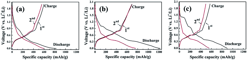 | ||
| Fig. 5 The initial two charge/discharge curves of CuxSny (x = 10 − y, y = 4.5, 7 and 9) alloys electrode at the current density of 100 mA g−1. (a) The sample with y = 4.5, (b) the sample with y = 7, and (c) the sample with y = 9. | ||
Fig. 6 shows the cycling behavior of CuxSny (x = 10 − y, y = 4.5, 7 and 9) alloys electrodes. The discharge capacity is remained to 600.7 mA h g−1 after first cycle and 261.8 mA h g−1 after 20th cycles, when y = 4.5. The coulombic efficiency is in the region of 94.63–94.65% in whole process except in the first cycle. However, the discharge capacities and coulombic efficiency are 761.6 mA h g−1 after first cycle, 457.8 mA h g−1 after 20th cycles and 90.63–91.37%, when y = 7. The higher discharge capacity of the sample with y = 7 than that with y = 4.5 is corresponded to the existence of slightly Sn rich in the Cu6Sn5 because the Sn has a higher theoretical capacity than that of Cu6Sn5. The decrease of coulombic efficiency could be attributed to the Sn decomposition and formation of SEI film on the surface of electrode. However, we observe the discharge capacities and coulombic efficiency are 557.6 mA h g−1 after first cycle, 151.8 mA h g−1 after 20th cycles and 88.81–93.02%, when y = 9. The decreased discharge capacity and coulombic efficiency could be attributed to the existence of excessively Sn rich in the Cu6Sn5 (Sn > Cu6Sn5). This leads the fact that the gigantic volume changes of Sn during cycling cause the breakdown of Sn particles and the loss of contact between each particle. Obviously, the discharge capacity of the sample with y = 7 increased 74.87% (from 261.8 mA h g−1 to 457.8 mA h g−1) and 201.58% (from 151.8 mA h g−1 to 457.8 mA h g−1), compared with the sample with y = 4.5 and 9, respectively. It indicates that slightly Sn rich in the Cu6Sn5 (Sn < Cu6Sn5) and Cu6Sn5–Sn core–shell structure can display an enhanced electrochemical performance.
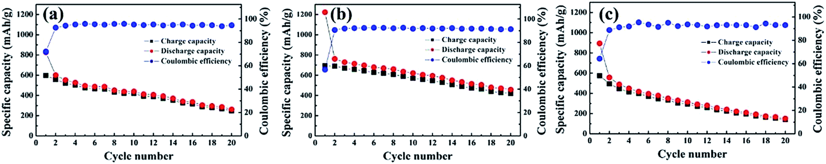 | ||
| Fig. 6 The cycling behavior of CuxSny (x = 10 − y, y = 4.5, 7 and 9) alloys electrodes. (a) The sample with y = 4.5, (b) the sample with y = 7, and (c) the sample with y = 9. | ||
Along with the galvanostatic cycling behavior, the rate discharge abilities of the CuxSny (x = 10 − y, y = 4.5, 7 and 9) alloys electrodes are shown in the Fig. 7. It can be seen that the sample with y = 7 shows an enhanced rate capability compared with the other ones with y = 4.5 or 9. The average discharge capacities of 800.5, 700.0, 599.6 and 429.4 mA h g−1 at current densities of 50, 100, 200 and 500 mA g−1 are delivered, separately. Importantly, the discharge specific capacity resumes to 500 mA h g−1 and maintains at the value of 492.3 mA h g−1 after 25 cycles when the current density is lowered to 50 mA g−1. For comparison, after 25 cycles at variational current density, the samples with y = 9 and 4.5 only maintain the discharge specific capacities of 296.1 and 218.2 mA h g−1, respectively.
 | ||
| Fig. 7 The rate capacity of CuxSny (x = 10 − y, y = 4.5, 7 and 9) alloys electrodes. (a) The sample with y = 4.5, (b) the sample with y = 7, and (c) the sample with y = 9. | ||
For supporting the possible reason for the difference performance of Cu6Sn5/Sn samples, the morphology of electrodes after 20 charge–discharge cycles are given. As shown in Fig. S4 (ESI†), the particle sizes of the sample with y = 9 is slightly lager than that of the samples with y = 7 or 4.5, which suggest that the secondary particle aggregation obviously occurs on the sample with y = 9. In addition, the thicknesses of the electrodes before and after 20 cycles are measured and compared. As exhibited in Table 1, the volume expansion ratio of the sample with y = 9 is 350%, which is evidently lager than that of the samples with y = 7 or 4.5. Both results indicate the drastic capacity fading in the sample with y = 9, namely, the samples with y = 7 or 4.5 with enhanced capacity retention rate. Notedly, the sample with y = 7 has no obviously increased volume expansion ratio in comparison with the sample with y = 4.5. Moreover, plus with the higher tin content, the sample with y = 7 can maintain higher specific capacity compared with the sample with y = 4.5.
| Samples | Before cycles | After 20th cycles | Volume expansion ratio |
|---|---|---|---|
| Cu6Sn5 (y = 4.5) | 10 μm | 27 μm | 270% |
| Cu3Sn7 (y = 7) | 10 μm | 28 μm | 280% |
| Cu1Sn9 (y = 9) | 10 μm | 35 μm | 350% |
Combined with the above results, it can be seen that the sample with y = 7 exhibits some enhanced lithium storage performances in comparison with the samples with y = 9 or 4.5 and other reported Cu–Sn-based alloy anodes as listed in Table 2. However, the cycling performance of the sample with y = 7 is also not excellent, although with some enhancements. For achieving the comprehensive results, we further improve the lithium storage performance of the sample with y = 7 by introducing the C additive based on our former obtained recipes. The Cu6Sn5/Sn/C composite is prepared by milling the obtained Cu6Sn5/Sn alloy with y = 7 and commercial graphite at a weight ratio of 85:15. As shown in Fig. 8, the obtained Cu6Sn5/Sn/C composite can maintain a discharge capacity of 605.8 mA h g−1 even after 100 repeated cycles at the current density of 100 mA g−1, which is larger than that of many reported Cu–Sn-based anodes such as the listed ones in Table 2. In consideration of the comparable electrochemical performance, the obtained Cu6Sn5/Sn/C composite is more suitable as an anode material for LIBs.
| Materials | Current density | Cycle numbers | Reversible capacity (mA h g−1) | References |
|---|---|---|---|---|
| Cu6Sn4 | 16.7 mA g−1 | 20 | ∼200 | 7 |
| Cu coated Cu–Sn alloy | 0.3 mA cm−2 | 50 | 220 | 12 |
| Uncoated Cu–Sn alloy | 0.3 mA cm−2 | 15 | 428 | 12 |
| Cu3.83Sn | 15 mA g−1 | 40 | ∼200 | 13 |
| Sn/Cu6Sn5 composite | 0.6 mA cm−2 | 50 | ∼370 | 14 |
| Porous Cu6Sn5 | 0.5 mA cm−2 | 30 | 420 | 19 |
| Cu6Sn5 alloy power | 0.1C | 20 | 313 | 20 |
| Microspherical Cu6Sn5 | 50 mA g−1 | 20 | 407 | 21 |
| 3D Sn–Cu alloy | 100 mA g−1 | 50 | 454 | 22 |
| Cu–Sn alloy | 0.25 mA cm−2 | 50 | 413.5 | 23 |
| Cu–Sn thin film | 50 mA g−1 | 100 | 300 | 24 |
| Sn–Cu/MWCNT composite | 150 mA g−1 | 30 | 439 | 25 |
| 3D Cu–Sn nanostructure | 0.3C | 50 | 590 | 26 |
| Sn–Co alloy film | 250 mA g−1 | 75 | 600 | 9 |
| 3D Ni–Sn alloys | 0.1 mA cm−2 | 200 | 500.5 | 10 |
| Sn–Fe–C | 100 mA g−1 | 100 | 494 | 11 |
| Cu3Sn7 (y = 7) | 100 mA g−1 | 20 | 457.8 | This work |
| Cu6Sn5/Sn/C | 100 mA g−1 | 100 | 605.8 | This work |
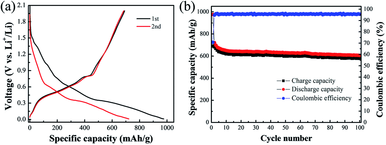 | ||
| Fig. 8 The lithium storage performances of Cu6Sn5/Sn/C composite electrode. (a) Voltage vs. specific capacity curve, (b) specific capacity vs. cycle number curve with corresponding coulombic efficiency. | ||
4. Conclusions
A simple and low-cost method using to prepare Cu6Sn5/Sn composite is developed. The structure and morphology of the obtained materials are investigated. It is found that the peaks of the obtained materials are mainly consistent with Cu6Sn5 and Sn phases. Furthermore, the Cu6Sn5/Sn composite with a core–shell structure displays an outstanding electrochemical performance, when used as the anode material for lithium ion batteries. Our work gives an effective solution to solve the gigantic volume change of Sn during cycling. Given its unique advantages, we believe this advanced method may have good potential for practical application in high energy lithium ion battery areas.Acknowledgements
This work is financially supported by the National Science Foundation of China (Project No. 11204102, 20111061, 21373198 and 51475207), the station Foundation of Ministry of Education for New Teachers (Project No. 20120061120041), Open Project of State Key Laboratory of Superhard Materials (Project No. 201410), and the China Postdoctoral Science Foundation (Grant No. 2015m580253).References
- Y. Zhang, L. Jiang and C. Wang, Nanoscale, 2015, 7, 11940–11944 RSC
.
- Y. Yang, D. Chen, B. Liu and J. Zhao, ACS Appl. Mater. Interfaces, 2015, 7, 7497–7504 CAS
- L. Wu, X. Hu, J. Qian, F. Pei, F. Wu, R. Mao, X. Ai, H. Yang and Y. Cao, Energy Environ. Sci., 2015, 7, 323–328 Search PubMed
- L. Sun, X. Wang, R. Susantyoko and Q. Zhang, Carbon, 2015, 82, 282–287 CrossRef CAS
- J. Chen, L. Yang, S. Fang, Z. Zhang and S. Hirano, Electrochim. Acta, 2013, 105, 629–634 CrossRef CAS
- J. Chen, L. Yang, S. Fang, S. Hirano and K. Tachibana, J. Power Sources, 2012, 199, 341–345 CrossRef CAS
- K. Kepler, J. Vaughey and M. Thackeray, J. Power Sources, 1999, 81, 383–387 CrossRef
- X. Wang, W. Han, J. Chen and J. Graetz, ACS Appl. Mater. Interfaces, 2010, 2, 1548–1551 CAS
- F. Ke, L. Huang, H. Wei, J. Cai, X. Fan, F. Yang and S. Sun, J. Power Sources, 2007, 170, 450–455 CrossRef CAS
- S. Woo, N. Okada, M. Kotobuki, K. Sasajima, H. Munakata, K. Kajihara and K. Kanamura, Electrochim. Acta, 2010, 55, 8030–8035 CrossRef CAS
- S. Yoon, J. Lee, H. Kim, D. Im, S. Doo and H. Sohn, Electrochim. Acta, 2009, 54, 2699–2705 CrossRef CAS
- W. Pu, X. He, J. Ren, C. Wan and C. Jiang, Electrochim. Acta, 2005, 50, 4140–4145 CrossRef CAS
- S. Beattie and J. Dahn, J. Electrochem. Soc., 2003, 150, A894–A898 CrossRef CAS
- R. Hu, M. Zeng and M. Zhu, Electrochim. Acta, 2009, 54, 2843–2850 CrossRef CAS
- R. Thomas, K. Rao and G. Rao, Mater. Express, 2014, 4, 65–71 CrossRef CAS
- Y. Cheng, Y. Shao, L. Parent, M. Sushko, G. Li, P. Sushko, N. Browning, C. Wang and J. Liu, Adv. Mater., 2015, 27, 6598–6605 CrossRef CAS PubMed
- X. Fan, X. Tang, D. Ma, P. Bi, A. Jiang, J. Zhu and X. Xu, J. Solid State Electrochem., 2014, 18, 1137–1145 CrossRef CAS
- M. Wu, X. Li, Q. Zhou, H. Ming, J. Adkins and J. Zheng, Electrochim. Acta, 2014, 123, 144–150 CrossRef CAS
- H. Shin and M. Liu, Adv. Funct. Mater., 2005, 15, 582–586 CrossRef CAS
- S. Ju, H. Jang and Y. Kang, J. Power Sources, 2009, 189, 163–168 CrossRef CAS
- X. Fan, F. Ke, G. Wei, L. Huang and S. Sun, Electrochem. Solid-State Lett., 2008, 11, A195–A197 CrossRef CAS
- X. Fan, Y. Shi, J. Wang, J. Wang, X. Shi, L. Xu, L. Gou and D. Li, Solid State Ionics, 2013, 237, 1–7 CrossRef CAS
- H. Zhao, C. Jiang, X. He, J. Ren and C. Wan, Ionics, 2008, 14, 113–120 CrossRef CAS
- D. Polat, J. Lu, A. Abouimrane, O. Keles and K. Amine, ACS Appl. Mater. Interfaces, 2014, 6, 10877–10885 CAS
- M. Uysal, T. Cetinkaya, M. Kartal, A. Alp and H. Akbulut, Thin Solid Films, 2014, 572, 216–223 CrossRef CAS
- Q. Deng, Z. Huang, X. Dai, Y. Wang, Z. Li and J. Li, J. Solid State Electrochem., 2015, 19, 1765–1771 CrossRef CAS
Footnote |
| † Electronic supplementary information (ESI) available. See DOI: 10.1039/c5ra23788b |
| This journal is © The Royal Society of Chemistry 2016 |