Controlling the corrosion rate and behavior of biodegradable magnesium by a surface-immobilized ultrathin 1-hydroxyethylidene-1,1-diphosphonic acid (HEDP) film

Meiyun Chen, Yingqi Chen, Wentai Zhang, Sheng Zhao, Juan Wang, Jinlong Mao, Wei Li, Yuancong Zhao, Nan Huang and Guojiang Wan*
Key Laboratory of Advanced Technologies of Materials, Ministry of Education, College of Materials Science and Engineering, Southwest Jiaotong University, Chengdu, 61003, China. E-mail: guojiang.wan@home.swjtu.edu.cn; superwgj@263.net; guojiang.wan@googlemail.com; Fax: +86 28 8760 0625; Tel: +86 28 8763 4146 ext. 802

Received 4th November 2015 , Accepted 19th January 2016

First published on 22nd January 2016


Abstract

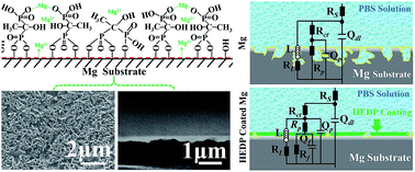
An ultrathin bisphosphonate film, 1-hydroxyethylidene-1,1-diphosphonic acid (HEDP), was deposited on magnesium for biodegradable implant applications. The small, bioactive HEDP molecule is supposed to be not only bio-safe, but also favorable for creating a highly protective layer for the control of the corrosion/degradation of Mg. In an in situ chemical sequence, the HEDP molecules were covalently surface-immobilized on the alkaline pretreated Mg and then spontaneously deposited by participation in a chelating reaction with Mg ions. An organometallic-like compound layer was thus formed, which was ascertained to be within the nanoscale and complied well with the substrate. The tape test showed that the HEDP film provides excellent adhesion strength. Electrochemical corrosion and in vitro immersion degradation investigations demonstrated that the HEDP coated Mg exhibited significantly slower corrosion rate than untreated Mg in phosphate buffered saline (PBS) solution. Of particular significance is the observation that HEDP coated Mg presented a remarkably suppressed localized corrosion mode. The meliorated corrosion/degradation behavior is credited to both the nature of the organometallic-like HEDP derivative layer, as well as the high quality of the film, with respect to compactness and homogeneity. Our HEDP modified Mg may bode well for application in biodegradable implants.


1. Introduction

Biodegradability is a new concept for biomedical implants that are needed to perform only transient scaffolding at best. The permanent existence of these implants is otherwise notoriously harmful and unnecessary, due to certain inevitable adverse side effects that are associated with the biomaterials' biocompatibility. The new paradigm therefore proposes to devise implants that can disappear naturally in the human body, after fulfilling their temporary assistance in lesion healing. This would help to circumvent adverse long-term biocompatibility reactions and exclude their cumbrous secondary removal operation.1–3 Magnesium and its alloys are increasingly being considered as the most promising metallic candidates for such biodegradable implant applications. This is essentially credited to their ease of bio-corrosion/degradation, suitable mechanical properties and unquestionable bio-safety, as compared with other metallic materials.4,5 In spite of such advantages over other metals and polymers, Mg still faces big challenges in its practical biodegradable applications. The biggest concern is that its corrosion rate (and therefore degradation process) in the human body is intrinsically very fast.6–8 From the electrochemical point of view, Mg is extremely active because of its comparatively low standard electrode potential, compared to other metals. This leads to magnesium always taking part in anodic dissolution when other neighboring impurities or phases are present in a corrosive medium.9 Furthermore, Mg has unique corrosion electrochemistry; the most well-known is the so-called negative difference effect (NDE). In the NDE, the cathodic hydrogen evolution on the Mg surface increases with the electrode being more anode-polarized, counteracting the electrochemical theory as observed with most other metals. The NDE effect may readily elicit the acceleration of the overall corrosion reaction.10–12 Apart from the corrosion rate, the corrosion mode is another concern that cannot be neglected from the clinical standpoint. In particular, the electrochemical corrosion behavior in this regard will govern the biodegradation rate pattern and thus the fate of implants.13 For instance, uniform corrosion is always desirable because any localized corrosion damage may cause a high risk for premature failure of the load-bearing implants.

Enormous efforts have been made to improve the corrosion resistance of Mg, which focus on both bulk-4,14,15 and surface-16–18 modifications. It turns out that bulk modification may provide only limited space for improvement, in that the Mg matrix is inherently prone to anodic dissolution by galvanic corrosion with any other phases, as mentioned above. Surface modification is regarded as being more adaptable because it may offer at least a kinetic barrier to protect Mg against corrosion. Moreover, the surface modifying layers can be more versatile for tuning biocompatibility. Various types of coating materials have been exploited on Mg, such as fluoride,16 zinc phosphate17 and titanium oxide,18 as well as organic or polymeric materials such as poly(1,3-trimethylene carbonate) (PTMC),19 polycaprolactone (PCL),20 and polylactide-co-glycolide (PLGA).21 Among these, inorganic materials are least applicable because they could work as the cathode, relative to the Mg matrix, to aggravate the corrosion reaction. Organic and polymer coatings are better in this regard, because they reduce the likelihood of galvanic corrosion because of their low electrical conductivity. Moreover, their biocompatibility may be more amenable, thanks to the diverse functional groups they usually have. For example, a series of organic phosphonic acids (PAs) [R-PO3H2] and their phosphonate ester derivatives [R-PO3R2] (R = alkyl, sometimes aryl) have been explored as coatings on Mg for bio-metal application.22–26 These organic coatings could potentially fulfill the dual-task of both corrosion-control and biocompatible functionality. Nonetheless, almost all the phosphonic acids utilized are relatively large molecules and their coatings are typically too thick (at least 1 μm, to even thicker than 10 μm). This may undermine the efficiency of mechanical compliance with the implants, which is critically important for those with complex-shapes or small sizes. On the other hand, the large molecules are unlikely to provide good quality coating in terms of compactness and homogeneity, which play a vital role in kinetically protecting Mg against corrosion. In addition, the larger the molecules, the less active groups they expose outward, which means a lower chance to fully employ their functionalities.24–26 More importantly, most of the current research is primarily concentrated on corrosion rate control, while paying little attention to tailoring the mode of corrosion.6,24–27 It is therefore of great importance to make more delicate designs with respect to the surface modification of Mg, to achieve a well-controlled corrosion behavior from the perspectives of both corrosion rate and mode, through a simply thinner layer.28 Some organic phosphonates of small molecules may presumably meet the requirements for creating a thin, compact and homogeneous layer that could efficiently meliorate the manner of the corrosion of magnesium.

1-Hydroxyethylidene-1,1-diphosphonic acid (abbreviated as HEDP, with molecular weight of 206.3 g mol−1) is a small molecule bisphosphonate. It is bio-safe/-friendly and already has wide applications in water treatment and cosmetics;29 more importantly, it also serves as an inhibitor in some instances of corrosion prevention.30 In spite of these properties, to date, there have been no reports on any study making use of HEDP to create surface modifying film on biodegradable metals. As a matter of fact, the HEDP molecule possesses a backbone structure of P–C–P (where C represents carbon and P correlates to a phosphonic group), which makes it analogous to some basic chemical components of human tissue, such as bone and cell membranes, and therefore potentially biocompatible. Furthermore, it offers the possibility of covalently anchoring to metal surfaces, molecule deposition, as well as chelating reactions with metallic ions to form a high quality coating.31

In this study, we propose the construction of a thin and compact organometallic-like layer on the magnesium surface, using the small bisphosphonate molecule, HEDP. As illustrated in Scheme 1, the rationale lies in the chemical surface-immobilization and chelation-enhanced deposition. Briefly, HEDP molecules can be chemically anchored to the alkaline-pretreated Mg substrate surface, first by means of covalent/neutralization reactions between their phosphate groups and the hydroxyl groups of the Mg(OH)2 layer. The spontaneous HEDP molecule deposition would occur subsequently, and this is accompanied by a chelating reaction with the Mg2+ ions released from the Mg substrate by corrosion. Eventually, a firmly fixed thin film of organometallic-like compound is likely to form on the Mg surface. Such a layer is supposed to ameliorate the corrosion behavior of Mg. Herein, the surface characteristics and mechanical adhesion of the prepared layer on Mg were ascertained systematically, and the corrosion behavior, with respect to both rate and mode, was assessed by electrochemical corrosion testing. Furthermore, the degradation performance was evaluated by an in vitro immersion investigation. Excellent mechanical compliance as well as significantly improved efficacy in controlling corrosion and degradation of the Mg bio-metal was accomplished by the prepared film that can be made ultrathin, which is credited to the nature of this layer, as well as its film quality brought about from the film deposition mechanism.


image file: c5ra23228g-s1.tif
Scheme 1 Schematic of the rationale for covalent immobilization and chelation-assisted deposition of 1-hydroxyethylidene-1,1-diphosphonic acid (HEDP) on the magnesium substrate.

2. Experimental

2.1 Materials

High purity (99.99%) as-cast Mg was purchased from Xinxiang Jiuli Magnesium Co. Ltd (Xinxiang, China). 1-Hydroxyethylidene-1,1-diphosphonic acid (HEDP, analytical grade, purity = 96%) was obtained from Aladdin Chemistry Co. Ltd (Shanghai, China). Phosphate buffered saline (PBS) solution was prepared, which is chemically composed of 8.1 g L−1 NaCl, 0.2 g L−1 KCl, 0.2 g L−1 KH2PO3 and 2.89 g L−1 Na2HPO3, pH = 7.2–7.4. All chemicals were of analytical grade and employed without any further purification.

2.2 Preparation of HEDP coating

Magnesium ingot was cut into disks of 1.5 mm in thickness and 10 mm in diameter as the substrate. The Mg substrates were mechanically ground in succession with SiC papers down to 2000 grit to smooth the surfaces. They were then ultrasonically cleaned in acetone, ethanol and distilled water (3 min for each one), to remove the surface contaminants. Thereafter, they were further rinsed with an acid solution (HNO3 22 g L−1, Mg2NO3 150 g L−1, ethanol 300 g L−1; 25 °C; ultrasonicated for 5–10 s) to chemically smooth the surface. The substrates were then ultrasonically cleaned in distilled water (for 1 min) and dried in a vacuum oven for further treatments. For alkaline pre-treatment, the Mg specimens were immersed in 3 M NaOH (at 60 °C, for 24 h) to produce a chemical conversion layer of Mg(OH)2 on the Mg surface; subsequently, they were rinsed with distilled water 3 times, dried in a vacuum oven, and were labeled as Mg-OH samples.

For HEDP deposition, the alkaline pretreated Mg specimens were immersed in HEDP solutions (in deionized water) with different concentrations (0.1, 0.5 and 1.0 g L−1) at 60 °C (the pH value was adjusted to 7 by 2 M NaOH) for 12 h. The deposited specimens were then thoroughly rinsed 3 times with deionized water, to wash the loose deposits from the surface, and finally dried in a vacuum oven. The HEDP coated Mg was labeled as Mg-OH@HEDP (0.1), Mg-OH@HEDP (0.5) and Mg-OH@HEDP (1.0) samples, referring to different deposited HEDP concentrations.

2.3 Characterization

The surface morphologies of the prepared samples were observed using field-emission scanning electron microscopy (FE-SEM, JSM-7401F JEOL, Japan) with an electron beam of 0.8 nm at 15 kV under a pressure of 4.45 × 10⁻⁴ Pa. Prior to all SEM observation, the samples were sputter-coated with a very thin layer of gold. In preparation for cross-section observation, the samples were sealed and fixed by embedding in epoxy resin, then they were mechanically ground (in succession with an SiC paper, down to 7000 grit, along the perpendicular direction of the sample surface), to expose the section faces of the samples and polished with water on a nylon paper. The polished specimens were washed 3 times with ethanol and dried in a vacuum oven, after which they were observed with FE-SEM.

Surface morphologies of the samples were further characterized using atomic force microscopy (AFM, SPI 3800, NSK Inc.). The observation was performed in tapping mode and the viewing fields were 10 μm × 10 μm to take images. The average root-mean-square roughness (Rrms) values were calculated along the diagonal lines using the JPKSPM 4.0 software, and they were statistically accounted on 4 random fields for one sample.

The adhesion strength of the HEDP film on the Mg substrate was measured by a cross-cut tape test, according to ASTM 3359-02.32 Grids of parallel cuts with 1 mm intervals were scratched on the coated samples. Scotch tape (3M Brand, USA) was attached firmly over the area of the grids, and after 90 s it was torn abruptly off at an angle as close to 180° as possible. Damage of the film was evaluated visually, using stereoscopic microscopy (OLYMPUS, SZX7-1093) with side illumination. The extent of damage is inversely related to adhesion strength, assigned as percentage of removed area relative to the entire surface. The samples were scored with grades as follows: 5 = almost 0%; 4 = less than 5%; 3 = 5–15%; 2 = 15–35%; 1 = 35–65%; 0 = over 65%. More detailed characteristics regarding the film damage were obtained after visually scrutinizing them under the stereoscopic microscope to determine their adhesion performance.

The chemical bonding states of the coatings were detected by Fourier transform infrared spectroscopy (FT-IR, Nicolet 5700, Thermo Electron Corporation, MA, USA), scanning from 500 to 4000 cm−1, and the data were converted into an absorbance spectrum. Prior to FT-IR detection, all samples were dried in a vacuum oven at 60 °C for 24 h to get rid of the disturbing ambient water absorption. The surface chemical composition and bonding states were further determined by X-ray photoelectron spectroscopy (XSAM800, Kratos Ltd, UK) with Al Ka (1486.6 eV) radiation at 12 kV × 15 mA at a pressure of 2 × 10⁻⁷ Pa. All binding energies in the XPS spectra were calibrated by locating the C 1s peak of the aliphatic carbon at 284.8 eV as reference. The high-resolution core-level XPS spectra were fitted by XPS peak 4.1 software to de-convolute the spectra with Shirley background mode.

2.4 Electrochemical corrosion measurement

Electrochemical tests, including open circuit potential (OCP) vs. time, potentiodynamic polarization (PDP) and electrochemical impedance spectroscopy (EIS), were conducted on an electrochemical workstation (IM6, Zahner, Germany). The electrolyte was the as-prepared PBS solution (pH 7.3, at 37 ± 0.5 °C). A three-electrode cell set-up was adopted, which consisted of a counter electrode of platinum foil (1 cm2), a saturated calomel reference electrode (SCE, Lei Ci 232, Shang Hai, China), and the samples as working electrodes. Each sample was connected electrically from the backside with a copper wire, and then sealed with silicone rubber to expose only a test surface area of 0.79 cm2. In principle, OCP reflects the electrode potential, whilst the anodic and cathodic reactions reach quasi-equilibrium and are always involved with the developing electrode surface. The OCP values of the samples as a function of time were monitored and recorded at a sampling frequency of 5 s intervals, up to 8 hours, to disclose the dynamic change of the surface state. Prior to all the PDP and EIS measurements, the working electrode was also allowed 30 min to stabilize in PBS on open circuit potential before commencing the potentiostatic scanning. The PDP curves were obtained by scanning the electrode potential from −2.0 to −1.0 VSCE at a scanning rate of 1 mV s−1. The polarization plots were analyzed by the Tafel method to specify values of free corrosion potentials Ecorr, corrosion current density icorr and cathodic Tafel slope βc, by linear extrapolation of the polarization curve. The region was taken over potential by about 50 mV more negative than the free corrosion potential, which is suitable for active Mg.33,34 For the anodic part of polarization, a breakdown potential (Ebd) was also identified that reveals the enduring limit against pitting attack for the coated samples. It shows typically a sudden increase in anodic current density. The corrosion mode was further examined by SEM observation of the specimen surface after the PDP test. The EIS spectrum was obtained at the fixed DC potential of the OCP value when the stabilization stopped. The excitation signal of a sinusoidal alternating voltage 10 mV (peak to peak) was superimposed on the DC potential, which was scanned from 200 kHz to 0.01 Hz. The acquired EIS data were decoded using the Zsim Demo software by fitting in light of pertinent equivalent electrical circuits.

2.5 Immersion degradation test

To assess the degradation behavior of the samples, in vitro immersion tests were implemented. Mg corrosion/degradation coincides with two most indicative variables, namely, hydrogen evolution and pH value change of the solution. Both were gauged respectively by means of immersion tests in PBS up to 500 h (at 37 ± 0.5 °C). For hydrogen evolution, the produced hydrogen was collected by a eudiometer, which was fixed up-side-down to cap over the tested specimens in PBS (400 mL). Prior to immersion, the specimens were sealed with epoxy resin, with an exposed area of 0.79 cm2. During immersion, the PBS solution was refreshed in part (200 mL) every seven days. This was to approximate real physiological conditions under clinical circumstances for implants.34 The surfaces of the samples after the immersion tests were further observed under SEM to determine their evolving degradation behavior. For pH value monitoring, the change was tracked during degradation in PBS (40 mL, for each sample) without refreshing the solution for the duration. The data was measured every 12 h using STARTER 3100 pH meter (OHAUS, USA). The number of each sample for statistical counting was no fewer than four.

3. Results and discussion

3.1 Surface characterization

Fig. 1a depicts surface SEM images of the HEDP coated Mg prepared at three different HEDP concentrations (0.1, 0.5 and 1.0 g L−1), as compared with Mg-OH and untreated Mg. The cross-sectional SEM images of the HEDP coated Mg samples are also shown. A deposited layer can be observed on all the Mg-OH@HEDP surfaces, relative to Mg-OH and bare Mg. It can be noted that the Mg-OH@HEDP (0.1) shows seemingly incomplete coverage of the film due to its ultrathin thickness, whereas the Mg-OH@HEDP (0.5) exhibits a more uniform film on the surface, and Mg-OH@HEDP (1.0) possesses a thicker, albeit non-uniformly aggregated coating. According to the cross-sectional images, all the films show distinct interfaces with the Mg substrate, indicating an efficient surface immobilization, and deposition of HEDP molecules onto the surface; the thicknesses of the films are 120 ± 20 nm for Mg-OH@HEDP (0.1), 410 ± 60 nm for Mg-OH@HEDP (0.5) and 920 ± 90 nm for Mg-OH@HEDP (1.0), and all fall within the nanoscale. This suggests also that the HEDP modifying layer complies well with the surface contour, being attached compactly unto the Mg substrate. Fig. 1b displays AFM images of Mg-OH@HEDP (0.5), as compared with Mg and Mg-OH. The Mg surface is relatively rougher due to the polished scratches. It appears that the Mg-OH surface became smoother with alkaline treatment because of the chemical leveling effect. It can be noted that the Mg-OH@HEDP (0.5) presents as negligibly rougher than the Mg-OH, both of which are apparently smoother than untreated Mg. The average root-mean-square roughness (Rrms) values are 136 ± 20 nm for Mg, 92 ± 7 nm for Mg-OH and 95 ± 13 nm for Mg-OH@HEDP (0.5), respectively.
image file: c5ra23228g-f1.tif
Fig. 1 Surface and cross-sectional morphologies of HEDP coated Mg, as compared with alkaline pretreated Mg and untreated Mg. (a) SEM images of Mg, Mg-OH and Mg-OH@HEDP (0.1, 0.5 and 1.0, respectively) samples, and representative cross-sectional SEM images of the HEDP coated Mg samples; (b) AFM images of Mg, Mg-OH and Mg-OH@HEDP samples.

Fig. 2 demonstrates the adhesion behavior of the HEDP films deposited on Mg substrate that have undergone the cross-cut tape test. Accordingly, all HEDP coated Mg samples exhibited no obvious macroscopic damage such as peeling-off or spalling of the film surface after removing the sticking tape. This denotes excellent adhesion, which can be scored grade 5 according to the standard of ASTM D3359. There is a slight difference among the three samples deposited at different HEDP concentrations (the higher magnification images). The difference manifests in the scratches as well as in the vicinity, i.e. on both the Mg-OH@HEDP (0.1) and Mg-OH@HEDP (0.5), the scratches look more distinct and remain relatively more intact after tape testing than the Mg-OH@HEDP (1.0), on which the damage to the film appears to be a little more severe, particularly near the edge of the scratches. This may be due to its greater thickness, as well as the relatively lower quality of the film, which will be discussed in the next section.


image file: c5ra23228g-f2.tif
Fig. 2 (OM) Surface morphologies of HEDP coated samples after tape-test measurements.

FT-IR spectra, as illustrated in Fig. 3, provide the chemical evidence for the existence of HEDP film deposited on Mg, relative to the Mg-OH and bare Mg. For alkaline pretreated Mg (Mg-OH), a strong peak, characteristic of the hydroxyl group (–OH), emerged at ca. 3700 cm−1 as compared to the bare Mg. This implies that a chemical conversion layer of Mg(OH)2 was formed with a large number of hydroxyl groups by alkaline pretreatment. On all the HEDP coated Mg samples, a certain number of peaks can be identified as belonging to the HEDP film; these include the P[double bond, length as m-dash]O stretching at approximately 1200 cm−1, P–OH at approximately 926 cm−1, and the R-PO3H2 group in the range from 1089 to 1320 cm−1. All these peaks correspond well to the pertinent peaks of the reference HEDP powder. Although it seems that most of these peaks appear slightly diminished and shifted in binding energy with respect to the HEDP powder, it is typically normal and they may be ascribed to the deprotonation of the phosphonic acid groups (R-PO3H2, e.g. P–OH and P[double bond, length as m-dash]O) on HEDP molecules, as well as the small amount of these molecules in such thin films.35,36 It is noteworthy that among the three HEDP coated samples, the relevant peaks became stronger with increased thickness.


image file: c5ra23228g-f3.tif
Fig. 3 FT-IR spectra of the HEDP coated Mg samples as compared with the alkaline treated Mg, untreated Mg and HEDP powder.

The chemical bonding states of the HEDP films are disclosed by XPS results, as shown in Fig. 4. The core–shell high-resolution spectra of P 2p, Mg 2p, O 1s and C 1s were detected for the Mg-OH@HEDP (0.5) sample in comparison with Mg-OH. Accordingly, the P 2p peak (132.5 eV) was detected on the Mg-OH@HEDP (0.5) surface, but was absent on the Mg-OH, further verifying that the deposition of the HEDP molecule was successful. More specifically, the P 2p band likely encompasses a typical phosphonic group peak and a shoulder contribution. The former can be designated to the phosphonic acid of HEDP, which can be further de-convoluted into a P2p1/2 peak (133.9 eV) and a P2p3/2 peak (132.8 eV), whereas the shoulder may be identified as P–O–Mg (131.0 eV).37–40 This attained P–O–Mg bonding denotes that the HEDP deposition was accompanied by the simultaneous chelating reaction with Mg ions. Likewise, the Mg 2p of Mg-OH@HEDP (0.5) apparently presents a new contribution that can be identified as P–O–Mg bonding at ca. 51.0 eV, as compared to Mg-OH. It can be noted that the Mg-O and Mg(OH)2 (or partly MgCO3) were also present on both the HEDP coated Mg and alkaline-pretreated Mg. It may be inferred that some of the Mg ions might also undergo precipitation and oxidation during the HEDP deposition. Concomitantly, for O 1s spectra, the HEDP coated Mg sample shows a noticeably wider band than that of the Mg-OH. This was brought about from the extra contributions, as well as binding energy shifting toward higher values, namely, the new existence of P–O–Mg (532.1 eV) and P–OH (532.2 eV). It can be noted that extra O bonding states associated with MgOH and MgCO3 (531.5 eV), MgO (530.5 eV) and H2O (534 eV) seemingly exist on HEDP-coated and uncoated Mg, which are commonly related to dissolved oxygen and carbon dioxide under ambient conditions.36–40 It would be unrealistic to decipher precisely all these seven contributions, therefore we labeled only their binding energy positions, as illustrated in Fig. 4c. The C 1s spectra (Fig. 4d) reveal more about the surface bonding states. There arose a new shoulder contribution (at 286.0 eV) for the Mg-OH@HEDP (0.5) surface, as compared with the Mg-OH, which can be assigned to the P–C–OH of HEDP molecules.35 Both C 1s bands for the HEDP coated and uncoated samples are centered around the main peak of 284.8 eV, which relates to C–C/C–H.36,39 For the HEDP coated sample, this main peak might partly be from the HEDP backbone, as well as the adventitious carbonaceous contaminants, whereas for Mg-OH this can only be from contamination. The peak at 289.1 eV was found on both HEDP coated and uncoated samples, which should be attributed to MgCO3 that may be generated by reaction of ambient CO2 with Mg ions in the air-formed oxide layer.41 The elemental compositions of the sample surface are listed in Table 1, as calculated by XPS survey results. It appears that only the HEDP coated surfaces present P element. It can be noted particularly that all samples exhibited excessive amount of Mg, which can be projected to the abovementioned multiple reactions of the Mg ions, such as chelation, precipitation, oxidation and carbonation.


image file: c5ra23228g-f4.tif
Fig. 4 XPS spectra of the HEDP coated Mg samples as compared with alkaline treated Mg and untreated Mg. (a), (b), (c) and (d) show high-resolution XPS spectra (P 2p, Mg 2p, O 1s and C1s, respectively) of the samples surfaces and their deconvolutions.
Table 1 Elemental composition of samples surfaces according to XPS survey spectra
Samples Composition (at%)
C Mg O P
Mg 21.93 24.53 53.54 0
Mg-OH 25.76 22.89 51.35 0
Mg-OH@HEDP (0.1) 31.79 17.28 49.37 1.56
Mg-OH@HEDP (0.5) 31.00 16.83 50.20 1.97
Mg-OH@HEDP (1.0) 31.35 16.20 50.74 1.71


All the abovementioned results support the fact that a high quality ultrathin HEDP film can be built up successfully on magnesium substrate, which may be interpreted by a series of unique reactions that involve the following. Theoretically, phosphonates (PAs) [R-PO3H2] and their phosphonate ester derivatives [R-PO3R2] (R = alkyl, sometimes aryl) tend to be chemically anchored to oxidized/hydroxylated metal surfaces.22,23 In our case, as illustrated in Scheme 1, a transitional layer of Mg(OH)2 was formed first by alkaline pretreatment to reinforce the anchoring effect, and the HEDP molecules can be more efficiently immobilized on the Mg(OH)2 surface through the neutralization reaction between their phosphonic groups and the hydroxyl groups of Mg(OH)2. Therefore, an initial densely packed HEDP monolayer is chemically fixed onto the alkaline pretreated magnesium surface.38 Deposition of HEDP molecules subsequently occurs on this base layer more readily, as a result of the intermolecular interactions (bonded or non-bonded). More importantly, the Mg ions released from corrosion of the Mg matrix will be mobilized by the HEDP molecules deposition, by virtue of so-called chelating. This helps to further prompt the in situ growth of the HEDP film, and also gives rise to a chelate compound, which is reportedly known as a type of stable metal phosphonate or organometallic framework.37–40 Such organometallic-like features render the layer more intensely compact, while the pervasive Mg2+ throughout the in situ developing layer, facilities more homogenous chelating reactions and therefore growth of the film. The small HEDP molecule would certainly be beneficial in making full use of such interactions. It turns out that all these facets might guarantee the establishment of a dense and uniform film of organometallic-like HEDP derivatives on the Mg substrate. The qualities of the coating, such as compactness and homogeneity, play a vital role in corrosion control for the metal substrate.

3.2 Electrochemical corrosion behavior

The biodegradation of metal is essentially an electrochemical corrosion process that can be suitably studied by electrochemical methods.34,42 The open circuit potential (OPC) of the samples, as shown in Fig. 5a, stands for the transient equilibrium of the potential arrived at by the electrode during corrosion. For untreated Mg, the OCP value was approximately −1.4 VSCE initially, then it decreased mildly toward a more cathodic/negative potential within the first 1 h. Thereafter, it slightly increased toward a more anodic/positive potential until 4 h, then was maintained (slightly higher than the initial value with only marginal fluctuation) in the rest period up to 8 h. Such a trend is typically attributable to the change in the Mg surface with ongoing corrosion, i.e. from more metal matrix exposure in the initial stage to more covering product formation after. For Mg-OH, the OCP started at a moderately lower value than the untreated Mg, perhaps because of the surface conversion layer of Mg(OH)2. There was a similar trend to Mg, which may be due to the potential for self-dissolution, as well as limited protection of this conversion layer against Mg corrosion. For the HEDP coated Mg, it was shown that their OCP values followed a different trend, compared to the untreated Mg and Mg-OH. Noticeably, the OCP of both Mg-OH@HEDP (0.1) and Mg-OH@HEDP (0.5) dropped toward more cathodic potential within the first 2 h, then their values were maintained at a relatively stable value, around −1.7 VSCE, for up to 8 h immersion, which was significantly more negative than that of the Mg (−1.4 VSCE). Such negative and static electrode potentials may manifest larger corrosion resistance for Mg. On the one hand, more negative OCP relates to a more cathodic polarized state, closer to the standard electrode potentials of Mg (−2.37 V), which renders the Mg surface less anodically polarized and therefore decreases its anodic dissolution. On the other hand, cathodic polarization is likely to slow down the cathodic hydrogen evolution according to the NDE effect on Mg;11,42,43 the more cathodically polarized the Mg surface is, the slower will be the hydrogen evolution reaction and thus, it will acquire a more reduced overall corrosion rate. It is worth noting that although the OCP of the Mg-OH@HEDP (1.0) also dropped to lower potential in the early stage, it fluctuated more conspicuously, as well as increased toward anodic. This might be attributed to the fact that it is thicker, albeit lower in quality (i.e. more aggregated and less compact, as shown in Fig. 1), as compared to the Mg-OH@HEDP (0.1) and Mg-OH@HEDP (0.5). In essence, the efficacy of corrosion protection relies solely on its thickness, instead of its quality. Loosely-packed film is more susceptible to the penetration of corrosive electrolyte, which will exacerbate the corrosion of the Mg matrix.
image file: c5ra23228g-f5.tif
Fig. 5 Electrochemical corrosion behavior of the HEDP coated Mg samples in PBS solution at 37 ± 0.5 °C as compared to Mg-OH and untreated Mg: (a) open circuit potential (OCP) monitoring for 8 h; (b) potentiodynamic polarization curves; (c) surface morphologies of the samples after PDP tests.

Fig. 5b shows the PDP curves of Mg-OH@HEDP (0.1, 0.5 and 1.0) samples as compared with the Mg-OH and Mg samples. Values of corrosion potential Ecorr, free corrosion current density icorr and cathodic Tafel slope βc, determined by the Tafel method, as well as breakdown potential (Ebd) are listed in Table 2. It was found that all HEDP coated Mg samples show apparently lower icorr than those of Mg-OH and bare Mg. Outstandingly, the Mg-OH@HEDP (0.5) sample exhibited the lowest salient icorr value (1.27 ± 0.30) × 10−6 A cm−2, which is about two orders lower than that of Mg (6.83 ± 1.55) × 10−4 A cm−2. The Mg-OH@HEDP (0.1) and Mg-OH@HEDP (1.0) also possess icorr values about one order lower than those of Mg-OH and the Mg samples. The protection efficiency (η) was obtained according to the equation as follows:44

 
image file: c5ra23228g-t1.tif(1)
where i0corr and icorr represent the free corrosion current density values of uncoated samples and those coated with HEDP, respectively. It shows that all the HEDP coated Mg samples provided remarkable protection efficiency, higher than 99.0%.

Table 2 The free corrosion potentials Ecorr, corrosion current densities icorr, cathodic Tafel slope βa, corrosion protection efficiency η and breakdown potential Ebd of the bare, alkaline-pretreated and HEDP coated magnesium samples in PBS solution at 37 ± 0.5 °C, according to potentiodynamic polarization curves
Samples Potentiodynamic polarization
Ecorr (VSCE) icorr (A cm−2) βc (V dec−1) η (%) Ebd (VSCE)
Mg-OH@HEDP (1.0) −1.36 ± 0.04 (3.48 ± 1.24) × 10−6 −0.09 ± 0.04 99.5 −1.17 ± 0.07
Mg-OH@HEDP (0.5) −1.30 ± 0.02 (1.27 ± 0.30) × 10−6 −0.75 ± 0.01 99.8 −1.09 ± 0.04
Mg-OH@HEDP (0.1) −1.60 ± 0. 05 (6.33 ± 0.85) × 10−6 −0.13 ± 0.03 99.1 −1.15 ± 0.05
Mg-OH −1.44 ± 0.07 (3.65 ± 0.78) × 10−5 −0.09 ± 0.03
Mg −1.42 ± 0.10 (6.83 ± 1.55) × 10−4 −0.37 ± 0.06 0


Beyond simply free corrosion current density, more details from the PDP curves disclose the impact of HEDP film on Mg corrosion protection such as the separate cathodic and anodic regions as well as rate-determining step (RDS). Specifically, for untreated Mg, its PDP shows a rapid acceleration of anodic dissolution with only a mild degree of polarization, which indicates the highly active state of the Mg surface. Therefore, the RDS should be the slowest step of the cathodic hydrogen evolution reaction, in accordance with the literature.45 The Mg-OH behaved similarly in terms of cathodic hydrogen evolution, as well as RDS, although its anodic region presented a slightly passive-like segment due to the partial protection of the Mg(OH)2 layer. For HEDP coated Mg, the sample with the smallest thickness (Mg-OH@HEDP (0.1)) provided remarkably reduced cathodic hydrogen evolution current density compared with that of untreated Mg and Mg-OH. It is worth noting that this reduced cathodic reaction is associated with the apparently negative shift of Ecorr, relative to the Mg and Mg-OH. This is in concert with the OCP results (Fig. 4a). When further anodically polarized, the Mg-OH@HEDP (0.1) presented steadily increasing anodic current density and finally got to a point comparable to that of Mg-OH. This implies that such ultra-thin HEDP layers perform additionally like anchored, efficient inhibitors, even though they may provide just a mild kinetic barrier protection. Interestingly, with increased thickness of the HEDP coating, the Mg-OH@HEDP (0.5 and 1.0) still show suppressed cathodic reaction, but not as strong as the Mg-OH@HEDP (0.1). Nonetheless, of significance is the anodic polarization region of the HEDP modified Mg that began to show greater kinetic barrier type protection against corrosion. It can be noted that both Mg-OH@HEDP (0.5) and (1.0) exhibit a passive-like section on their anodic parts, which register relatively noble values of Ebd. The Mg-OH@HEDP (0.5) demonstrates the highest noble Ebd of −1.09 ± 0.04 VSCE, whereas the Mg-OH@HEDP (0.1) yields a slightly more negative value of −1.17 ± 0.07 VSCE. Such constrained anodic dissolution is contrary to Mg-OH and Mg, which have obviously faster counterparts. In general, the Ebd of coating deposited metals is regarded as an indication of the capability of resisting localized corrosion damage in corrosive media. Principally, a more positive (towards anodic) Ebd implies that the coating is more effective and stable in the suppression of localized corrosion.46 Thus, the Mg-OH@HEDP (0.5) offers the most stable Ebd and predicts the highest resistance to localized corrosion. In theory, the OCP as well as Ecorr shift toward more cathodic potential, brought about by such a film can be credited to the chemical nature of the phosphonic acid, as well as its strong chemical adsorption on the metal surface, which account for its ability to act as a corrosion inhibitor.39,41 On the other hand, this favorable negative rest potential is able to restrain the hydrogen cathodic reaction of RDS due to the NDE effect of Mg corrosion,9,11,13 and therefore reduce the overall corrosion reaction.

Fig. 5c portrays the surface morphologies of the samples after PDP testing, exposing more details in corrosion mode. It was observed that the surface of Mg-OH@HEDP (0.5) remained relatively intact after PDP scanning, with a localized corrosion area less than 5%, and only a tiny amount of products. The other two HEDP modified Mg samples retained well-protected surfaces, although it appears that they undertook a few more attacks as compared to the Mg-OH@HEDP (0.5). By contrast, on both Mg and Mg-OH, severe localized corrosion attacks are visible over more than 90% of the entire surface. Specifically, Mg suffered severe localized corrosion that was widespread on its surface, and Mg-OH experienced filiform-like corrosion damage to its Mg(OH)2 layer. Both such corrosion modes are critically harmful for biomedical implants, in that they will elicit a greater likelihood of premature failure. Thus, for the HEDP coated Mg, their more uniform corrosion profile is of vital importance for the bio-metal to maintain its integrity and durability.

EIS offers a powerful method to decipher the kinetic parameters of the corrosion process.47 Fig. 6 presents EIS spectra of both Nyquist and Bode types for the samples, as well as their fitted plots based on corresponding equivalent electrical circuits. According to the EIS spectra, all the impedance values of HEDP modified Mg (Fig. 6a) are significantly larger than those of Mg-OH and Mg (Fig. 6b). Of noteworthy interest is the fact that both the Mg-OH and Mg exhibit a distinctly separated inductive loop, relative to the capacitive loop, which suggests a sign of severe localized attack, whereas for the HEDP modified Mg, the inductive loops seem to be diminished or blended with the capacitive loop. This implies that a much lower degree of localized corrosion occurred on the modified sample. To more accurately decode their kinetics in the overall corrosion, two equivalent circuit models were applied (embedded EC in Fig. 6a for HEDP coated Mg, and in Fig. 6b for Mg and Mg-OH) to quantitatively fit the EIS spectra. Rs is the solution resistance, Qdl is a constant phase element representing the double layer capacitance, Rct represents the interfacial charge transfer resistance (associated mostly with the corrosion reaction), Qp and Rp relate to the constant phase element capacitance of the newly formed layer (adsorption product or conversion of Mg(OH)2) and the electrolytic diffusion resistance through the layer, respectively. RL and L stand for the resistance and inductance regarding localized galvanic corrosion cell reactions, Qf and Rf refer to the constant phase element capacitance and resistance of HEDP film, respectively. The fitting results are listed in Table 3. An important indicator of the ease of corrosion, roughly referred to as Rct, is associated with the resistance of interfacial charge transfer and accounts mostly for the overall corrosion reactions. It can be noted that the three HEDP coated Mg samples exhibit remarkably higher Rct values than Mg-OH and Mg. In particular, the Mg-OH@HEDP (0.5) has Rct that is two orders larger than Mg and Mg-OH. This is well in agreement with the PDP results. More distinct differences are revealed in the Bode plots (Fig. 6c and d). Accordingly, all HEDP coated Mg reached higher values than Mg-OH and Mg at low frequency, with respect to the impedance modulus, Z. For instance, the module Z of Mg-OH@HEDP (0.5) was as large as about 1.5 × 10⁶ Ω cm2, 2 orders magnitude higher than that of Mg-OH (6.2 × 10³ Ω cm2) and Mg (1.7 × 10³ Ω cm2). As clarified in the phase angle diagram, there appeared three time-constant loops on each sample that attest to their corresponding equivalent electrical circuit models.48 The capacitive loop in the high frequency region denotes the electric double layer, which is accompanied by interfacial charge transfer (mainly the corrosion anodic and cathodic reactions herein); the capacitive loop in the medium frequency region signifies the formed nonmetallic layer (such as the modifying layer and corrosion product), which is parallel to the electrolyte/water diffusion resistance within. The inductive loop in the low frequency region stands for actively unstable surface charging and discharging processes such as localized galvanic corrosion cell reaction.42 It is worth noting that a significant difference exists in the inductive components among the HEDP coated Mg samples and the bare Mg, as well as Mg-OH. For the Mg and Mg-OH, a separated inductive loop is clearly presented at low frequency, which generates a positive phase angle. For the HEDP coated Mg samples, their inductive components are much less distinguished. It may be inferred that they overlapped with the capacitive loops, which does not suffice to shift the phase angle to the positive sense. It can be noted that Mg-OH@HEDP (0.5) has an almost negligible inductive component. Our abovementioned results reveal that HEDP coated Mg underwent much less localized corrosion attack, compared with Mg and Mg-OH. According to the literature,49 a more accurate theoretical passivation resistance Rp can be deduced from the impedance at zero frequency, instead of the Rct. In that case, our HEDP modified Mg samples would provide even larger Rp than Mg and Mg-OH.


image file: c5ra23228g-f6.tif
Fig. 6 Electrochemical impedance spectra (EIS) of the HEDP coated Mg samples in PBS solution at 37 ± 0.5 °C, as compared to alkaline treated Mg and untreated Mg; the raw data (scatter plots) and model fits (solid lines) are shown. (a), (b) Nyquist EIS spectra. (c) Bode-impedance EIS spectra. (d) Bode-phase EIS spectra.
Table 3 The representative fitting results of electrochemical impedance spectra of the HEDP coated Mg samples compared to alkaline-treated and untreated Mg in PBS solution at 37 ± 0.5 °C
Samples Nyquist EIS fitting results
Rs Ω cm2 Qdl × 10−6 sn Ω−1 cm−2 n1 Rct × 103 Ω cm2 Qp × 10−6 sn Ω−1 cm−2 n2 Rp Ω cm2 Qf × 10−5 sn Ω−1 cm−2 n3 Rf × 103 Ω cm2 L × 103 H cm2 RL × 103 Ω cm2
Mg-OH@HEDP (1.0) 10 0.65 0.67 154.2 4.1 0.75 2605 7.78 0.52 2.8 598.4 21.9
Mg-OH@HEDP (0.5) 17 0.76 0.61 327.4 3.5 0.88 8583 11.53 0.76 4.2 1336.0 57.8
Mg-OH@HEDP (0.1) 19 1.86 0.66 113.0 7.2 0.85 613 7.22 0.68 8.7 42.8 11.2
Mg-OH 48 15.90 0.84 3.4 12.5 0.73 1320 8.5 4.8
Mg 27 5.69 0.80 1.3 52.4 0.76 211 3.6 2.9


Despite the nature of the compound layer, from the perspective of electrochemistry the kinetic factors may contribute equally. Our obtained thin, albeit high quality HEDP film would effectively hinder the electrolyte penetration pathway into the Mg matrix underneath, and therefore retard the corrosion. It needs to be emphasized that the film quality aspects, such as compactness and homogeneity, might play a more important role in determining the corrosion rate than solely the thickness. This was reflected in the fact that the thicker HEDP coated Mg, prepared under higher HEDP concentration, performed more poorly than the thinner HEDP coated Mg, in our case. This may be explained by the fact that the high concentration tends to speed up the HEDP molecule deposition rate, whereas reducing the chance for sufficient chelating reactions with Mg ions, which needs both space and time. It is therefore likely that the too-fast deposition with high concentration does not necessarily warrant a greater proportion of Mg-chelated HEDP of high quality. Probably, optimal conditions exist that are in keeping with that of Mg-OH@HEDP (0.5). For instance, the appropriate concentration of HEDP might offer a good match between the number of hydroxyl sites on the pretreated Mg surface and the number of the HEDP molecules arriving on the top layer for initial nucleation, which is quite the same in the sequential deposition process but needs to be studied further.

Alongside the reduced corrosion rate, of more practical significance is the suppressed localized corrosion achieved on the HEDP modified Mg. This can be interpreted as is schematically elucidated in Fig. 7. The efficacy of suppression for localized corrosion of the HEDP deposited Mg entails the physiochemical model embedded with the related equivalent electrical circuits, in contrast to the untreated Mg. It appears that the additional retarding components, such as Qf and Rf, as well as the increased magnitude of the shared components (Qdl, Rt and L, RL), lead to good control of the localized corrosion by the protective film (clarified in the SEM observation results on the right in Fig. 7). Interestingly, our results also purport to strongly correlate the localized corrosion with inductive phenomenon found in EIS spectra. In principle, localized galvanic corrosion generates the rapid changing of self-circulating currents, which may induce an inductive loop when subjected to EIS testing. Although there exist multiple explanations concerning the inductive phenomenon, among them are immediate Mg+, porous metastable diffusion as well as active species absorption;10,50,51 these were found and discussed with respect to the bare metal surface only. Our findings on this ultrathin film modified Mg offers an expanded platform for better understanding this phenomenon. It is clearly suggested that the constrained localized corrosion can be well linked to weak inductive contribution.


image file: c5ra23228g-f7.tif
Fig. 7 Schematic showing the efficacy of corrosion control by the HEDP layer on Mg, highlighting suppressed localized corrosion.

3.3 Immersion degradation behavior

The in vivo degradation of Mg metal is a dynamic bio-corrosion process, and in vitro immersion tests are routinely used to examine the degradation behavior.34,49 According to the corrosion reaction of magnesium, Mg + H2O = Mg2+ + 2OH + H2(g), one mole magnesium corrodes to produce exactly one mole of hydrogen, as well as two moles of hydroxyl ions. Therefore, we can assess the Mg degradation rate though the hydrogen evolution and the pH value variation. Fig. 8 shows the in vitro degradation results of samples in PBS up to 500 h. Accordingly, a remarkable subdued hydrogen evolution, as well as a slowed-down increase in pH value was gauged on the HEDP modified Mg compared to the Mg-OH and Mg for the whole immersion period. Moreover, their discrepancies became even larger with the elapse of immersion time. Among all the samples, the Mg-OH@HEDP (0.5) performed best in degradation control by providing the lowest amount of hydrogen evolution (1.35 mL cm−2) as compared to the Mg-OH (2.8 mL cm−2) and Mg (5.3 mL cm−2). The Mg-OH@HEDP (0.1) and Mg-OH@HEDP (1.0) also had lower values (2.6 and 2.25 mL cm−2, respectively) as compared with Mg-OH and Mg. The course of degradation can be divided into three stages: In the early stage, till 80 h, a steep increase in H2 evolution occurred on the Mg sample, indicating the rapid dissolution of Mg, whilst HEDP coated Mg experienced just a slight increase in hydrogen evolution because of the film protection. From 80 h to around 300 h, although the acceleration of hydrogen evolution seemed to decrease on Mg because of the accumulation of corrosion products, a high rate was still maintained. In contrast, the HEDP modified Mg underwent a very modest increase in hydrogen evolution. Up to 500 h, Mg held a high rate, while the HEDP modified Mg maintained a steady and slower hydrogen evolution. A similar change was embodied in the pH monitoring (Fig. 8b), particularly in the early stage. In the later stage, the pH values of HEPD coated Mg dropped even lower, probably due to the chemical degradation of the HEDP film into acid products, indicating it does not refer solely to Mg corrosion in this instance.20–23 Moreover, it should be mentioned that the buffering effect of PBS may bring about an underestimation of the pH value change, which also happens in the human body.24–26
image file: c5ra23228g-f8.tif
Fig. 8 Immersion degradation behavior of the HEDP coated magnesium samples in PBS solution at 37 ± 0.5 °C for 500 hours, as compared with alkaline treated Mg and untreated Mg. (a) Hydrogen evolution and (b) pH value change as a function of time; (c) SEM micrographs of the samples surfaces after immersion degradation in PBS solution at 37 ± 0.5 °C for 500 hours.

Fig. 8c displays the SEM images of the surface morphologies of samples after hydrogen evolution tests to unveil their degradation. Accordingly, the Mg suffered severe degradation, which was characterized by heavily localized attack, as well as the accompanying products. The degradation of Mg-OH seemed to occur mainly underneath the converted Mg(OH)2 layer, which only partially protected Mg against corrosion, as this layer appeared to have been peeled-off gradually. The HEDP modified Mg still had a full coverage of the protective layer as compared to the Mg-OH. Among them, the Mg-OH@HEDP (0.5) remained mostly intact and had a comparatively uniform degradation. The ultrathin and high quality HEDP film thus provides good control over the degradation of Mg with respect to both rate and mode.

The outstanding capability for corrosion/degradation control achieved by our HEDP film can be credited to the nature of the HEDP organometallic compound, as well as its protective efficaciousness. From both thermodynamic and kinetic points of view, HEDP film offers a tenable measure to tailor the corrosion of such highly active Mg, and more importantly, provides long-term stability in controlling its bio-degradation. Thermodynamically, such an organometallic compound apparently renders the modified Mg surface more negative toward cathodic potential. This favorable state associated with cathodic rest potential is able to restrain the hydrogen cathodic reaction because of the NDE effect mentioned above.10,51 This is different for many other metals that depend on passivation to prevent corrosion, which require sufficiently high anodic polarization to produce the passivation protective layer such as the oxide. More importantly, such thermodynamic aspects may ensure excellent corrosion/degradation control simply by means of the ultrathin film, otherwise it must resort to the kinetic alternative by increasing the thickness. Of course, the kinetic effect also plays a decisive part in protection of Mg against corrosion. In this regard, the quality of the film in terms of compactness and homogeneousness is thus pivotal to prohibiting the electrolyte penetration into the Mg matrix. Thus, it can be safely said that our organometallic-like HEDP derivative film can impose synergic effects on Mg corrosion control, and needless to say, the ultrathin attribute, as well as mechanical compliance are fundamentally beneficial to improving the overall performance of biodegradable implants.

4. Conclusion

A dense and homogenous HEDP film was successfully deposited on pure magnesium that was pretreated with alkali. The thickness of the film can be tailored to the nanoscale. It was ascertained that such an ultra-thin film has excellent adhesion strength, complying well with the Mg substrate. This type of film was built up through a sequence of chemical immobilization, in situ deposition, combined with Mg2+ chelation. An organometallic-like compound layer was thus established on Mg. Such chemically anchored, Mg-chelated, HEDP modified Mg offered not only a significantly slower corrosion/degradation rate, but also a remarkably suppressed localized corrosion in PBS. Such improved corrosion behavior is credited to kinetic protection brought about by the HEDP film, as well as the nature of the HEDP derived organometallic-like compound, which renders the Mg surface more favorably cathodic and hence slows down the rate of the hydrogen cathodic reaction. Of practical significance is the fact that the HEDP modified Mg is relatively free of localized corrosion, which is highly desirable for bio-implant application.

Acknowledgements

This study was financially supported by the National Natural Science Foundation of China under Grant no. of 21473138, Sichuan Youth Science & Technology Foundation (2012JQ0001) for Distinguished Young Scholars, and Education Program for Innovation Entrepreneurship of Southwest Jiaotong University.

References

  1. Y. F. Zheng, X. N. Gu and F. Witte, Mater. Sci. Eng., R, 2014, 77, 1 CrossRef.
  2. M. P. Staiger, A. M. Pietaka, J. Huadmai and G. Dias, Biomaterials, 2006, 27, 1728 CrossRef CAS PubMed.
  3. M. Haude, R. Erbel and P. Erne, Lancet, 2013, 381, 836 CrossRef CAS.
  4. F. Witte, N. Hort, C. Vogt, S. Cohen, K. U. Kainer, R. Willumeit and F. Feyerabend, Curr. Opin. Solid State Mater. Sci., 2008, 12, 63 CrossRef CAS.
  5. X. Gu, Y. Zheng, Y. Cheng, S. Zhong and T. Xi, Biomaterials, 2009, 30, 484 CrossRef CAS PubMed.
  6. D. Gopi, N. Murugan, S. Ramya and L. Kavitha, et al., RSC Adv., 2015, 5, 27402 RSC.
  7. J. Wang, V. Giridharan, V. Shanov, Z. Xu, B. Collins, L. White and Y. Yun, Acta Biomater., 2014, 10, 5213 CrossRef CAS PubMed.
  8. M. Curioni, Electrochim. Acta, 2014, 120, 284 CrossRef CAS.
  9. G. Williams, N. Birbilis and H. N. McMurray, Electrochem. Commun., 2013, 36, 1 CrossRef CAS.
  10. R. L. Petty, A. W. Davidson and J. Kleinberg, J. Am. Chem. Soc., 1954, 76, 363 CrossRef CAS.
  11. M. Curioni, F. Scenini and F. Bellucci, et al., Electrochim. Acta, 2015, 166, 372 CrossRef CAS.
  12. R. F. Schaller, S. Thomas and N. Birbilis, Electrochem. Commun., 2015, 51, 54 CrossRef CAS.
  13. Y. C. Xin, T. Hu and P. K. Chu, Corros. Sci., 2011, 53, 1522 CrossRef CAS.
  14. N. Hort, Y. Huang, D. Fechner, M. Störmer, C. Blawert, F. Witte and F. Feyerabend, Acta Biomater., 2010, 6, 1714 CrossRef CAS PubMed.
  15. X. N. Gu, X. H. Xie, N. Li, Y. F. Zheng and L. Qin, Acta Biomater., 2012, 8, 2360 CrossRef CAS PubMed.
  16. Y. C. Su, Y. B. Lu, Y. C. Su, J. J. Hu, J. S. Lian and G. Y. Li, RSC Adv., 2015, 5, 56001 RSC.
  17. L. Y. Niu, Z. H. Jiang, G. Y. Li and C. D. Gu, Surf. Coat. Technol., 2006, 200, 3021 CrossRef CAS.
  18. J. Hu, C. Zhang, B. Cui, K. Bai and S. Zhu, et al., Appl. Surf. Sci., 2011, 257, 8772 CrossRef CAS.
  19. J. Wang, Y. H. He, M. F. Maitz, K. Q. Xiong, L. S. Guo, Y. H. Yun, G. J. Wan and N. Huang, Acta Biomater., 2013, 9, 8678 CrossRef CAS PubMed.
  20. Y. Chen, Y. Song, S. Zhang and X. Zhang, et al., Biomed. Mater., 2011, 6, 025005 CrossRef PubMed.
  21. J. N. Li, P. Cao, X. N. Zhang, S. X. Zhang and Y. H. He, J. Mater. Sci., 2010, 45, 6038 CrossRef CAS.
  22. C. ́ m. Queffé lec, M. Petit, P. Janvier, D. Andrew Knight and B. Bujoli, Chem. Rev., 2012, 112, 3777 CrossRef PubMed.
  23. S. P. Pujari, L. Scheres, A. Marcelis and H. Zuilhof, Angew. Chem., 2014, 53, 6322 CrossRef CAS PubMed.
  24. Y. Q. Chen, S. Zhao, B. Liu, M. Y. Chen, J. L. Mao, Y. C. Zhao and G. J. Wan, ACS Appl. Mater. Interfaces, 2014, 6, 19531 CAS.
  25. S. Zhao, Y. Q. Chen, B. Liu, M. Y. Chen, J. L. Mao, Y. C. Zhao and G. J. Wan, J. Biomed. Mater. Res., Part A, 2015, 103, 1640 CrossRef PubMed.
  26. Y. Li, S. Cai, G. H. Xu, S. B. Shen and X. H. Sun, et al., RSC Adv., 2015, 5, 25708 RSC.
  27. G. L. Song and Z. M. Shi, Corros. Sci., 2014, 85, 126 CrossRef CAS.
  28. H. Zhang, R. F. Luo, W. J. Li and J. Wang, Corros. Sci., 2015, 94, 305 CrossRef CAS.
  29. P. Yin, Z. Wang and R. Qu, J. Agric. Food Chem., 2012, 60, 11664 CrossRef CAS PubMed.
  30. H. Zhao, S. Cai, Z. T. Ding, M. Zhang and G. H. Xu, RSC Adv., 2015, 5, 24586 RSC.
  31. M. Othmani, A. Aissa, C. G. Bac and F. Rachdi, Appl. Surf. Sci., 2013, 274, 151 CrossRef CAS.
  32. ASTM 3359-02, Standard Test Methods for Measuring Adhesion by Tape Test1, PA 19428–2959, USA, 2002 Search PubMed.
  33. Z. Shi and M. Liu, Corros. Sci., 2010, 52, 579 CrossRef CAS.
  34. F. Witte, J. Fischer, J. Nellesen, H. A. Crostack, V. Kaese, A. Pisch, F. Beckmann and H. Windhagen, Biomaterials, 2006, 27, 1013 CrossRef CAS PubMed.
  35. K. Pohl, J. Otte, P. Thissen, M. Giza, M. Maxisch, B. Schuhmacher and G. Grundmeier, Surf. Coat. Technol., 2013, 218, 99 CrossRef CAS.
  36. M. C. Zenobi, C. V. Luengo, M. J. Avena and E. H. Rueda, Spectrochim. Acta, Part A, 2008, 70, 270 CrossRef PubMed.
  37. G. X. Wang, N. N. Cao and Y. Y. Wang, RSC Adv., 2014, 4, 59772 RSC.
  38. T. Ishizaki, M. Okido, Y. Masuda, N. Saito and M. Sakamoto, Langmuir, 2011, 27, 6009 CrossRef CAS PubMed.
  39. G. Zorn, I. Gotman, E. Y. Gutmanas, R. Adadi, G. Salitra and C. N. Sukenik, Chem. Mater., 2005, 17, 4218 CrossRef CAS.
  40. B. Adolphi, E. Jähne, G. Busch and X. Cai, Anal. Bioanal. Chem., 2004, 379, 646 CrossRef CAS PubMed.
  41. M. Jönsson, D. Persson and D. Thierry, Corros. Sci., 2007, 49, 1540 CrossRef.
  42. Y. Zhang, C. Yan, F. Wang and W. Li, Corros. Sci., 2005, 47, 2816 CrossRef CAS.
  43. V. Shkirskiy, A. D. King, O. Gharbi, P. Volovitch, J. R. Scully, K. Ogle and N. Birbilis, ChemPhysChem, 2015, 16, 536 CrossRef CAS PubMed.
  44. J. Hu, D. Zeng, Z. Zhang, T. Shi, G. L. Song and X. Guo, Corros. Sci., 2013, 74, 35 CrossRef CAS.
  45. Y. Q. Chen, G. J. Wan, J. Wang, S. Zhao and N. Huang, Corros. Sci., 2013, 75, 280 CrossRef CAS.
  46. J. Liang, P. B. Srinivasan, C. Blawert and W. Dietzel, Electrochim. Acta, 2010, 55, 6802 CrossRef CAS.
  47. M. Naumowicz, Z. A. Figaszewski and L. Poltorak, Electrochim. Acta, 2013, 91, 367 CrossRef CAS.
  48. K. Popov, H. Ronkkomaki and L. H. J. Lnjunen, Pure Appl. Chem., 2001, 73, 1641 CrossRef CAS.
  49. A. D. King, N. Birbilis and J. R. Scully, Electrochim. Acta, 2014, 121, 394 CrossRef CAS.
  50. G. Song, A. Atrens, D. St John, X. Wu and J. Nairn, Corros. Sci., 1997, 39, 1981 CrossRef CAS.
  51. W. J. Liu, F. H. Cao, Y. Xia and J. Q. Zhang, Electrochim. Acta, 2014, 132, 377 CrossRef CAS.

This journal is © The Royal Society of Chemistry 2016
Click here to see how this site uses Cookies. View our privacy policy here.