Activated carbon from Luffa cylindrica doped chitosan for mitigation of lead(II) from an aqueous solution

Asha H. Gedam*a and Rajendra S. Dongreb
aDepartment of Allied Science, Cummins College of Engineering for Women, Nagpur – 441 110, India. E-mail: agedam.ccoew@gmail.com; Fax: +91 7104 280304; Tel: +91 9730184638
bPost Graduate Teaching Department of Chemistry, Rashtrasant Tukdoji Maharaj Nagpur University, Nagpur – 440 033, India

Received 28th October 2015 , Accepted 29th January 2016

First published on 2nd February 2016


Abstract

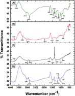
The present study is concerned with the batch adsorption of toxic lead(II) ions from an aqueous solution using activated carbon from a Luffa cylindrica fibers doped chitosan (ACLFCS) biocomposite as an adsorbent. The adsorption experiments were conducted as a function of pH, agitation time, initial lead(II) ion concentration and adsorbent dose. The synthesized biosorbent was characterized by instrumental techniques such as XRD, FTIR, SEM, BET surface area and BJH pore size distribution. XRD analysis revealed that the synthesized ACLFCS adsorbent exhibited broad diffraction peaks, reflecting an amorphous structure. FTIR study showed various functionalities, such as C[double bond, length as m-dash]O, –OH and –NH2, which were responsible for lead(II) adsorption on the ACLFCS biocomposite. The surface morphology of the ACLFCS adsorbent possesses a porous texture with round- and elliptical-shaped voids that can provide adsorption sites for the adsorbate. BJH pore size distribution analysis showed an average pore diameter >2 nm for all chitosan (CS), activated carbon of Luffa cylindrica (ACLF) and ACLFCS adsorbents, corresponding to the presence of a mesoporous structure. Batch adsorption of lead(II) ions was carried out at room temperature wherein the optimum conditions for the maximum adsorption of lead(II) ions were attained at pH 5 with an adsorbent dose of 0.1 g L−1. The equilibrium adsorption isotherm data were fitted by the Langmuir and Freundlich models and the Langmuir isotherm exhibited the best fit with the experimental data. The maximum removal of lead(II) obtained was 98% (experimental) and 112 mg g−1 (from the Langmuir isotherm model). The adsorption kinetics was evaluated using pseudo-first-order, pseudo-second-order and intraparticle diffusion models. The adsorption data follows a pseudo-second-order kinetic model. The high uptake of lead(II) ions using ACLFCS indicates an effective and low cost adsorbent for the treatment of water contaminated with lead(II) ions.


1. Introduction

The presence of lead in water, air and soil environments, even as traces, has detrimental effects on plants and animals. The natural sources of lead are soil erosion, volcanic eruptions, sea sprays and bush fires. Industries engaged in lead-acid batteries, paint, oil refining, metal plating, phosphate fertilizer, electronics, wood production, combustion of fossil fuel, mining activity, automobile emissions, and sewage wastewater release lead into wastewater.1 Lead toxicity causes serious dysfunction of the liver, kidney, reproductive system and central nervous system, reduction in hemoglobin formation, mental retardation, infertility and abnormalities in pregnant women. Due to the hazardous nature of lead(II), it can, directly or indirectly, cause anemia, headache, chills, diarrhea, encephalopathy, hepatitis, nephritic syndrome and even death.2 The World Health Organization (WHO) in 1995 proposed a safe total lead limit of 50 ppb in drinking water, which was decreased to 10 ppb in 2010.3 The permissible limits of lead in drinking water as set by the European Union (EU), the United States Environmental Protection Agency (USEPA)4 and Guidelines for Canadian Drinking Water Quality5 are 10 ppb, 15 ppb and 10 ppb, respectively. However, more recently, an EPA document recommended a zero lead value in a national primary drinking water standard.6 Techniques that are extensively used for the abatement of lead from wastewaters are chemical precipitation, membrane filtration, reverse osmosis, electrochemical reduction, ion exchange and adsorption. Among the aforementioned technologies, adsorption has been preferred due to its cheapness and efficacy with respect to heavy metal removal, even at trace levels. Recently, bioadsorbents7 and activated carbon obtained from agricultural by-products rich in cellulose, lignin, pectin and tannin, which can serve as adsorption sites for heavy metal ions, have been prominently used for wastewater treatment. The production of activated carbons from abundantly available agricultural waste allows the conversion of unwanted waste to useful, valuable adsorbents. Activated carbon derived from rubber tires has been used for the removal of pesticides and chromium,8,9 whereas fertilizer waste10 has been studied with respect to the removal of contaminants from water. Adsorbents, such as bagasse fly ash for the treatment of wastewater containing DDD, DDE,11 and phenol,12 were also reported. Removal of hazardous dyes from wastewater using bottom ash,13,14 and carbon nanotubes15 has been reported in the literature. Novel adsorbents, viz. orange peel and Fe2O3 nanoparticles for cadmium removal,16 and Duolite C-433 for Pb(II) ion removal,17 have also been investigated as effective adsorbents.

Chitosan, a nitrogenous polysaccharide, used as a cationic biosorbent, is obtained in enormous amounts. It is a heterogeneous polymer, which is composed of 2-amino-2-deoxy-D-glucopyranose and residual 2-acetamido-2-deoxy-D-glucopyranose.18 Chitosan shows high affinity for metal ions due to the presence of amine (–NH2) and hydroxyl (–OH) groups. Chitosan can bind with both anionic and cationic species; however, it has low stability due to its hydrophilic nature and sensitivity to pH. It is soluble in most organic acids, is non-porous and has a low specific surface area.19 To improve the chemical and mechanical strength of chitosan, several attempts at physical and chemical modification were carried out. Various chitosan-based adsorbents, such as bromine-pretreated chitosan composites20 and chitosan clay composites,21 for lead(II) ion removal, have been reported. Chitosan modified by granular activated carbon for the adsorption of humic acid,22 chitosan-coated carbon for heavy metal adsorption23 and an activated carbon/chitosan composite for simultaneous adsorption of aniline and Cr(VI) ions,24 have been investigated.

The main scope of this communication is to study the modification of chitosan (CS) by doping it with activated carbon from Luffa cylindrica fibers (ACLF) to achieve an activated carbon from a Luffa cylindrica doped chitosan (ACLFCS) biocomposite and further to utilize it for the adsorption of lead(II) ions from water. Luffa cylindrica is mainly a lignocellulosic material composed of cellulose, hemicelluloses and lignin (60%, 30% and 10% by weight, respectively),25 belonging to the cucurbitaceous family. It is abundantly available as an agricultural residue in many developing countries such as India, Korea, China, Central America and Japan. Consequently these disposed, unconventional and widely available Luffa cylindrica fibers can be transformed into an activated carbon, which is a carbonaceous material that possesses highly developed porosity, a large surface area, relatively high mechanical strength and a variety of functional groups on its surface. The transformation of agricultural residue into an activated carbon ultimately provides a way to reduce its environmental burden or hazards. The cationic nature of CS and the anionic nature of ACLF produced a stable, granular ACLFCS biocomposite due to two oppositely charged interactions. The purpose of doping CS with ACLF is to explore the expected synergistic effects achieved through the incorporation of certain functionalities in the resultant biocomposite that are responsible for adsorption of lead(II) ions.

To the best of our knowledge, there are no published reports on the removal of lead(II) ions from water using ACLFCS. Neither has the ability of ACLFCS to adsorb other heavy metal ions been reported. This allows more adsorption studies to be conducted using ACLFCS to find out whether the new surface chemistry of modified chitosan has an impact on lead(II) removal from water. The present investigation aims to explore the characterization of ACLFCS using FTIR, SEM, XRD, BET analysis and accordingly to use this biocomposite for batch adsorption of lead(II) ions from water at various parameters, viz. pH, agitation time, adsorbent dosage and initial lead(II) ion concentration. Langmuir and Freundlich isotherms were used to evaluate the equilibrium adsorption data. The adsorption rates were also determined based on pseudo-first-order and pseudo-second-order kinetic and intraparticle diffusion models.

2. Materials and methods

2.1 Synthesis of ACLFCS biocomposite

Luffa cylindrica fruit was collected from the state of Maharashtra, India. The covering of Luffa cylindrica was peeled off and the exposed fibers/wood inside were washed several times with distilled water to remove dirt and dust particles. The fibers/wood were sun-dried for 2 days and cut into 1–2 cm pieces. The pieces were then oven dried at 80 °C for 3–4 hours. Pyrolysis of Luffa cylindrica fibers was carried out in a modified muffle furnace. During pyrolysis, nitrogen at a flow rate of 100 mL min−1 was used as purge gas. The furnace was heated at a rate of 10 °C min−1 from room temperature to 700–800 °C and was maintained at this temperature for 1 h. The sample was allowed to cool and was ground to obtain fine powdered activated carbon. The CS (degree of deacetylation > 90%) was dissolved in 3% acetic acid heated at 40–50 °C blended with ACLF in a 1[thin space (1/6-em)]:[thin space (1/6-em)]1 ratio. The mixture was stirred with a magnetic stirrer at 800 rpm at room temperature for 6 hours and then dropped in 50% aqueous ammonia. Finally, the mixture was filtered, washed several times with distilled water and dried in an oven at 80 °C. The prepared adsorbent, ACLFCS, was ground to fine powder and used for various adsorption experiments.

2.2 Characterization of ACLFCS

Characterization of ACLFCS was carried out to understand the mechanisms of lead adsorption.

Fourier transform infrared (FTIR) spectroscopy was recorded in the range of 450–4000 cm−1 to study the functional groups and the surface chemistry of the adsorbent, using a Perkin-Elmer Spectrum one FTIR spectrometer, USA. An FTIR spectrum of a sample was obtained using the KBr pressed-pellet method, wherein a homogeneous mixture of sample mixed with KBr in a ratio of 1[thin space (1/6-em)]:[thin space (1/6-em)]50 was made. The surface morphology of the synthesized biocomposite was studied using a Scanning Electron Microscope (SEM, Zeiss Sigma, Germany) at an accelerating voltage of 15 kV. The samples were mounted on carbon tapes and supported on a metallic disc. SEM images were taken at different magnifications in the range of 20× to 5000×. X-ray diffraction (XRD) measurements were taken with a Rigaku MiniFlex2 goniometer, using a Cu Kα radiation source operating under a voltage of 30 kV and a current of 15 mA. X-ray diffraction patterns were collected at a scan rate of 5 °C min−1. The Brunauer–Emmett–Teller (BET) surface area of the sample and the Barrett–Joyner–Halenda (BJH) pore size distribution was determined using a nitrogen adsorption–desorption method at 77 K using a Micromeritics ASAP 2020 V3.04 H analyzer (USA). During analysis, the sample was degassed at 100 °C under vacuum and helium was used as a carrier gas.

Elemental analysis (C/H/O/N/S) of samples (3 mg) was performed using an elemental analyzer (Vario EL Cube) at 230 V. For each analysis, the standard, sulfanilic acid, was first analyzed to ensure that the experimental error remained within ±1%.

2.3 Analysis of lead(II) ions

The concentration of lead(II) ions during batch adsorption experiments was determined using an atomic absorption spectrophotometer (SensAA, GBC Scientific Equipment) with lead hollow cathode lamps and an air–acetylene mixture as an oxidant at a wavelength of 283.3 nm. Deuterium background correction was used and the spectral slit width was 1.3 nm. The amount of light absorbed by the test lead(II) ion solutions was compared to the amount of light absorbed by a set of standard lead(II) solutions of known concentration. A digital pH meter (Hanna Instruments) was used for pH measurement of lead(II) ion solutions. The pH meter was standardized using pH 4 and pH 9 buffer solutions (Fisher Scientific, India). A rotary shaker (Remi, India) at 200 rpm was used for agitating the samples during batch adsorption experiments. Three replicates were used for each adsorption experiment and average values for lead(II) ion concentrations are reported.

2.4 Lead(II) ions adsorption experiments

Batch adsorption experiments were carried out to study the effect of various operating parameters, viz. pH, adsorbent dosage, initial metal ion concentration and agitation time, on the adsorption rate. All chemicals used were of analytical reagent grade. A standard solution of 1000 mg L−1 of lead(II) was prepared by dissolving lead(II) nitrate (Merck, India) and experimental solutions of the required mg L−1 concentration were prepared from standard lead(II) nitrate solution by successive dilutions with double-distilled water. All adsorption experiments were carried out at room temperature (27 ± 1 °C) in 250 mL Erlenmeyer flasks containing 100 mL of test solution agitated on a rotary shaker at 200 rpm. The effect of pH on the percentage removal of lead(II) was studied over the pH range of 2–8, using a known volume of 35 mg L−1 lead(II) solution. The required pH of the solutions was adjusted by adding 0.1 N HNO3 or 0.1 N NaOH, using a digital pH meter. A specified dose of adsorbent was added to lead(II) solution and agitated at room temperature at 200 rpm for a specified period of time. Supernatant liquids obtained by filtration through Whatman filter paper-41 were analyzed for residual lead(II) ion concentrations using an atomic absorption spectrophotometer (AAS).

For further adsorption experiments on the lead(II) solutions, the pH was fixed at the optimum value of 5. The effect of adsorbent dosages (0.01–0.15 g L−1) on the equilibrium adsorption of lead(II) was studied by keeping other parameters constant. Similarly, the effect of varying contact time in the range of 2–20 minutes for different lead(II) ion concentrations from 35 to 115 mg L−1 at room temperature (27 ± 1 °C) was studied to evaluate the adsorption efficiency. The reaction mixture was agitated on a rotary shaker at 200 rpm and the supernatant liquid was filtered and analyzed by AAS for the residual lead(II) ion concentration.

The percentage removal of lead(II) was calculated using eqn (1)

 
image file: c5ra22580a-t1.tif(1)

Adsorption capacities were calculated using eqn (2) and (3) as follows:

 
image file: c5ra22580a-t2.tif(2)
 
image file: c5ra22580a-t3.tif(3)
where qe (mg g−1) and qt (mg g−1) were the quantities of lead(II) ions adsorbed at equilibrium and at time t, respectively, Co (mg L−1) and Ce (mg L−1) were the initial and equilibrium lead(II) ion concentrations and Ct (mg L−1) was the residual lead(II) ion concentration at time t. V (L) represents the volume of solution and m (g) the mass of adsorbent.

3. Results and discussion

3.1 Physicochemical characterization of ACLFCS biocomposite

3.1.1. FTIR analysis. FTIR spectroscopy is used to determine the presence and absence of particular functional groups. Table 1 lists the functional groups and Fig. 1 shows the infrared spectra of CS, ACLF and ACLFCS before and after lead(II) adsorption.
Table 1 Surface functional groups of CS, ACLF and ACLFCS before and after lead(II) adsorption
Wavenumber (cm−1) Assignment References
CS ACLF ACLFCS before adsorption ACLFCS after adsorption
3660 3754 3760 Hydroxyl (O–H stretch)  
3073 3389 Hydroxyl (O–H stretch)  
  2977 2993 2981 Aromatic C–H stretch  
2876 2883 2889 Stretching vibrations of C[double bond, length as m-dash]O in carbonyl Xie et al.28
896 Aromatic C–H out-of-plane bending vibrations  
1667 1696 NH bending vibration of NH2 of chitosan Konaganti et al.29
1530 –NH bending in amide Ramya et al.30
1524 1531 1518 Aromatic C[double bond, length as m-dash]C stretch Ghali et al.31
1262 Vibration of NHCO group (amide III band)  
1287 1299 1293 Phenol C–O stretch  
1077 1071 1074 C–O–C in glycoside linkage  
990 Saccharide structure  
    894 767 CH3–COH stretch  
1434 Bending vibration of methyl group  
1375 Bending vibration of methylene group  
1152 1158 1152 –CH vibration  
1040 C–O–C stretching vibration  


image file: c5ra22580a-f1.tif
Fig. 1 FTIR of (A) CS (B) ACLF (C) ACLFCS before lead(II) adsorption and (D) ACLFCS after lead(II) adsorption.

In the ACLFCS biocomposite, the characteristic absorption bands of CS at 2876 cm−1, 1667 cm−1 and 1077 cm−1, which correspond to the stretching vibration of C[double bond, length as m-dash]O in carbonyl, the NH bending vibration of the NH2 group and the C–O–C stretch, were shifted to 2883 cm−1, 1696 cm−1 and 1071 cm−1, respectively. Similarly, the characteristic absorption bands of ACLF at 2977 cm−1, 1524 cm−1 and 1287 cm−1 for the aromatic C–H stretch, the aromatic C[double bond, length as m-dash]C stretch and the phenolic C–O stretch shifted in ACLFCS to 2993 cm−1, 1531 cm−1 and 1299 cm−1, respectively. FTIR spectra revealed the physical and chemical interactions between CS and ACLF due to which the peaks of both CS and ACLF were observed in the ACLFCS biocomposite.26 ACLFCS spectra also revealed corresponding changes in the characteristic absorption peaks compared to pure CS and ACLF. The shift in absorption peaks in ACLFCS indicates mixing and doping of ACLF with CS.

The spectral investigation of lead loaded ACLFCS showed either decrease or disappearance of peak intensity might be related to lead(II) adsorption.27 FTIR spectra of lead-loaded ACLFCS show some shift in wavenumber. For instance the bands at 2883 cm−1, 1531 cm−1, 1299 cm−1, and 1071 cm−1 shifted to 2889 cm−1, 1518 cm−1, 1293 cm−1 and 1074 cm−1, respectively, suggesting the involvement of C[double bond, length as m-dash]O functionalities in lead(II) adsorption on ACLFCS. Similarly, absorption bands at 3760 cm−1 and 1696 cm−1, corresponding to –OH stretching vibrations and –NH bending vibrations of the –NH2 group, disappeared, suggesting the participation of –OH and –NH2 in lead(II) adsorption. Thus, the FTIR study revealed that various functionalities, such as C[double bond, length as m-dash]O, –OH and –NH2, are responsible for lead(II) adsorption on ACLFCS.

3.1.2. BET and elemental analysis. N2 adsorption–desorption isotherms and BJH-based pore size distributions of CS, ACLF and ACLFCS are shown in Fig. 2(A) and (B), respectively, and detailed data on BET surface areas and PSDs is represented in Table 2.
image file: c5ra22580a-f2.tif
Fig. 2 (A) Nitrogen adsorption vs. desorption isotherm (B) BJH-based pore size distribution of CS, ACLF and ACLFCS biocomposite.
Table 2 Pore structure parameters of CS, ACLF and ACLFCS adsorbenta
Sorbents BET (m2 g−1) Vtotal (cm3 g−1) Vmicro (cm3 g−1) Vmeso (cm3 g−1) Mean pore diameter (Å)
a Herein, Vtotal: total pore volume, Vmicro: micropore volume, Vmeso: mesopore volume of CS, ACLF and ACLFCS.
CS 3.5 4.582 × 10⁻³ 4 × 10⁻³ 5.82 × 10⁻⁴ 52.36
ACLF 285 0.2076 0.1861 0.0215 29.13
ACLFCS 138 0.1117 0.0989 0.0128 32.37


The surface area of the synthesized ACLFCS adsorbent was higher with respect to pure CS and lower with respect to ACLF. The decreased surface area of ACLFCS may be due to the blockage of internal porosity of ACLF by CS and successful blending between them. The surface area of the adsorbent is one of the physical parameters related to adsorption. The adsorptive capacity of the adsorbent increases with increasing surface area for a pure physisorption process. In the present study, the physisorption capacity of ACLFCS for lead(II) ion removal is limited and adsorption mainly occurred via chemisorption. In ACLFCS, even though the surface area decreased, it incorporated functional groups, such as –NH2, –OH and C[double bond, length as m-dash]O, which were responsible for lead(II) adsorption. These related functionalities were confirmed by FTIR.

The N2 adsorption–desorption isotherms for CS are of type II, according to IUPAC classification, with a very narrow hysteresis loop indicative of mesoporous materials. In contrast, ACLF demonstrates a typical type IV isotherm and displays a broad H2 hysteresis loop in the range of 0.4–1.0 P/Po, which is characteristic of ordered mesoporous materials. The ACLFCS biocomposite has a combined isotherm of two individual components, viz. CS and ACLF, along with an intermediate value for specific surface area and pore volume compared to those of CS and ACLF. In ACLFCS, there is a hysteresis loop at a relative pressure above 0.4, indicative of mesoporosity. The appearance of intermediate mesoporosity in the biocomposite may arise from interspaces between CS and ACLF with different framework structures. The average pore diameters (pore diameter > 2 nm) shown in Table 2 correspond to the presence of mesoporous structures for the CS, ACLF and ACLFCS adsorbents. Due to a satisfactory BET surface area, the prepared biocomposite is reasonably suitable for lead(II) adsorption.

The burnt carbonaceous portion leaves a residue called ash, which is not required and is considered as an impurity in activated carbon. The ash content was found to be low at 4.3%, which is in the normal range of ash contents found in most agricultural waste. The prepared biocomposite resembles a good adsorbent. The density of a carbonaceous adsorbent plays a vital role in adsorption. Carbon with a higher bulk density will be more efficient in removal of contaminants. According to Itodo et al., (2008) bulk density has an impact on the adsorbate-retention level by any adsorbent.32 Higher density carbons hold more adsorbate per unit volume. It was verified that there is a linear relationship between porosity and bulk density prior to adsorption. Higher porosity carbon was apparently denser. It is the porosity that determines the surface area for the adsorbate. In this study, the average bulk density of ACLFCS was found to be 0.69 g mL−1 (Table 3).

Table 3 Proximate and ultimate analysis of ACLFCS adsorbent
Sorbent Ultimate analysis (%) Proximate analysis (%)
C H N S O Moisture Volatile matter Ash Fixed carbon
ACLFCS 50.94 5.14 1.57 0.29 42.06 8.92 47.78 4.3 39


3.1.3. SEM analysis. To confirm the adsorption of lead(II) ions onto ACLFCS biocomposite and for better insight regarding the alteration of the surface morphology after metal ion adsorption, SEM analysis was applied. An SEM image of pure CS is shown in Fig. 3(A). SEM images of ACLFCS before lead(II) adsorption are shown in Fig. 3(B) and (C), whereas ACLFCS after lead(II) adsorption is represented in Fig. 3(D) and (E). The surface morphology of CS appeared to possess an uneven texture, bumpiness and porous cavities. ACLFCS before lead(II) adsorption, as shown in Fig. 3(B) and (C), possesses a porous texture with round and elliptical-shaped voids that can provide adsorption sites for the adsorbate and consequently represents a different surface morphology compared to pure CS. The surface morphology of ACLFCS after lead(II) adsorption, as depicted in Fig. 3(D), shows the accumulation of new, shiny white clumps on the adsorbent surface; similarly, Fig. 3(E) revealed the appearance of reduced pore sizes due to the coverage of a smooth, whitish layer on the adsorbent. SEM images of lead(II)-loaded adsorbent indicated that its capacity was exhausted, which was not observed before metal loading. It followed that the adsorbent cavities were occupied/filled by lead(II) ions after adsorption.
image file: c5ra22580a-f3.tif
Fig. 3 SEM characterization of (A) CS at 250×, (B) ACLFCS before lead(II) adsorption at 250× and (C) at 100×, and (D) ACLFCS after lead(II) adsorption at 250× and (E) at 100×.
3.1.4. XRD. XRD patterns of pure CS, ACLF and ACLFCS before and after lead(II) adsorption are shown in Fig. 4(A)–(D). The X-ray diffraction pattern of CS, as shown in Fig. 4(A), exhibited a broad diffraction peak at 2θ = 20° with a d-spacing of 4.2 Å, which is characteristic of semi-crystalline chitosan. The peaks are broadened due to the amorphous nature of the CS polymer. Several researchers reported activated carbon as an amorphous carbon.33–35 The prepared ACLF, as depicted in Fig. 4(B), shows an amorphous structure. There are two broad peaks observed near 2θ = 24° and 42° that are common in activated carbon and are assigned to (002) and (10) reflections. In ACLFCS before lead(II) adsorption, as shown in Fig. 4(C), the XRD pattern shows both a peak at 2θ = 19.28° corresponding to CS and a small hump at 2θ = 42°, characteristic of ACLF, which was completely absent in pure CS. The abovementioned results show that doping of ACLF with CS was effective in achieving an ACLFCS biosorbent. The XRD pattern of lead-loaded adsorbent, as shown in Fig. 4(D), identified a lead mineral on the surface of ACLFCS as hydrocerussite-Pb3(CO3)2(OH)2. The precipitation of hydrocerussite on ACLFCS might be attributed to the contribution of specific surface functional groups.36 The XRD pattern of lead-loaded adsorbent was identified using JCPDS file no. 13-0131. XRD analysis of lead-adsorbed ACLFCS showed typical peaks at 2θ = 19.94°, 19.98°, 24.76°, 27.22°, 34.18°, 35.94°, 40.48°, 42.36°, 44.02°, 49.02°, 53.96°, 57.9° and 75.76°, corresponding to (101), (012), (104), (015), (110), (113), (202), (024), (205), (119), (122), (114) and (312) Bragg reflections. Thus, the presence of lead peaks in lead-loaded ACLFCS shows the adsorption of lead(II) ions on the adsorbent surface.
image file: c5ra22580a-f4.tif
Fig. 4 XRD of (A) CS (B) ACLF (C) ACLFCS before lead(II) adsorption and (D) ACLFCS after lead(II) adsorption.

3.2 Effect of pH

The pH of the solution is a key factor affecting solution chemistry, chemical speciation of metal ions and the degree of ionization of functional groups on an adsorbent surface. Chemical reactions, such as hydrolysis, complexation, redox and precipitation, are intensely influenced by pH.37 The effect of pH on lead(II) adsorption is shown in Fig. 5. The results showed that the percentage uptake of lead(II) increased significantly as the pH increased from 2 to 5 and attained equilibrium at pH 6, whereas a decreased lead(II) adsorption is observed over the pH range of 6–8. Adsorption was thus negatively correlated with an acidic medium. The main species of lead(II) is Pb2+ under weakly acidic conditions, i.e. at pH < 6. At pH 6, Pb2+ and Pb(OH)+ are in equal concentration. Under increasingly alkaline conditions, viz. a pH range of 7–9, lead forms hydroxides such as Pb(OH)+, which eventually precipitate as Pb(OH)2 at pH >9 and Pb(OH)3 at pH >11. At lower pH values, i.e. pH < 5, adsorption was repressed, possibly as a result of an increased H3O+ ion concentration that competes with positively charged metal ions for adsorption sites on the adsorbent. Accordingly, the adsorption of lead(II) on ACLFCS at pH < 5 could be the result of cation exchange reactions. As the pH increased, i.e. at pH 5 to 6, high adsorption of lead(II) occurred, which can be attributed to the increased negative charge density on the adsorbent, which weakens the competition between H3O+ and lead(II) ions for the adsorbent surface. Thus, the improved adsorption of lead(II) ions at pH 5–6 is governed by electrostatic interactions. The decreased adsorption at higher pH (>6) is probably due to metal hydrolysis and precipitation of lead(II) as lead hydroxides. Therefore, the adsorption process is a combination of ion exchange and precipitation. In this study, an optimum pH of 5 was recorded for lead(II) removal and therefore further adsorption experiments were carried out at this pH value. The region wherein there is a sharp increase in adsorption capacity from low to high pH is known as the pH adsorption edge.38 In this study, the pH adsorption edge was 2–5.
image file: c5ra22580a-f5.tif
Fig. 5 Effect of pH on lead(II) adsorption.

3.3 Effect of dose of adsorbent

The effect of the adsorbent dosage at room temperature (27 ± 1 °C) on lead(II) adsorption is shown in Fig. 6. The result showed that the percentage removal of lead(II) increases with increase in adsorbent dosage (0.01–0.1 g L−1) with an adsorption capacity of 81% to 98% at the optimum pH, 5. It was observed that lead(II) uptake rapidly increased with increasing adsorbent dosage from 0.01 to 0.1 g L−1 and no further substantial uptake of lead(II) ions occurred when the dose of adsorbent was increased further. This is expected because, as the adsorbent dose increases, the number of adsorbent particles and consequently the number of adsorption sites increases, allowing easier penetration of lead(II) ions. A further increase in adsorbent dose has no significant effect on the percentage lead(II) removal as the system reaches equilibrium. The maximum adsorption occurred at a dosage of 0.1 g L−1. Thus, an optimum adsorbent dosage of 0.1 g L−1 is justified for economical purposes.
image file: c5ra22580a-f6.tif
Fig. 6 Effect of adsorbent dose on lead(II) adsorption.

3.4 Effect of contact time on different lead(II) ion concentrations

Adsorption of lead(II) ions as a function of contact time for varying lead(II) ion concentrations from 35 mg L−1 to 115 mg L−1 at pH 5 is shown in Fig. 7. The plot shows that the rate of lead(II) ion adsorption consisted of two phases; an initial rapid phase and a second slower equilibrium phase of adsorption. The result indicated that the uptake of lead(II) ions increases with time from 2 to 15 minutes with a maximum 98% (for 35 mg L−1) to 86% (for 115 mg L−1) lead(II) removal efficiency and thereafter, the rate of adsorption become slower near the equilibrium. It was found that the time required to attain equilibrium is relatively short compared to similar experiments reported in the literature.39 The results confirmed that with a fixed dose of adsorbent at an increasing lead(II) ion concentration, the amount adsorbed increased but the adsorption percentage decreased. Initially, lead(II) ions are rapidly removed as large numbers of unoccupied adsorbent surface sites are available for adsorption. As the system approaches equilibrium, the accumulation of lead(II) ions on the vacant sites results in limited mass transfer of the adsorbate from the bulk liquid to the external surface of the adsorbent.21 From Fig. 7, it is also evident that the percentage removal of lead(II) decreases as the initial lead(II) ion concentration increases. This can be explained by the fact that at high lead(II) ion concentrations, the available apparent external adsorbent sites are already occupied, which prevents diffusion of lead(II) ions on the adsorbent surface.
image file: c5ra22580a-f7.tif
Fig. 7 Effect of contact time on lead(II) ion adsorption at different initial concentrations.

3.5 Regeneration studies

The percentage desorption of lead(II) ions is depicted in Fig. 8. In the present study, five adsorption–desorption cycles were carried out at a lead(II) ion concentration of 35 mg L−1. 0.01 g of lead-loaded ACLFCS adsorbent was washed with distilled water, air dried and placed in contact with 0.1 M HCl as desorption agent in a 250 mL Erlenmeyer flask. Desorption experiments were carried out at pH < 3. The flasks were agitated at 200 rpm at 27 °C for 1 h to ensure equilibrium. 0.1 M HCl was found to be a better desorbing agent at pH 2 due to the high quantity of H+ ions in the solution. This results in exchange of ions, where H+ takes the place of lead(II) ions in solution. To investigate the process of lead(II) desorption, the lead(II) ion concentrations present in 0.1 M HCl were analyzed using an atomic absorption spectrophotometer. The percentage desorption of lead(II) was calculated using eqn (4) as follows;
 
image file: c5ra22580a-t4.tif(4)
where CAds and CDes are the concentrations of lead(II) ions adsorbed and desorbed (mg L−1), respectively. The results show that the percentage recoveries of metal ions decreased by 28% at the end of the fifth adsorption–desorption cycle due to saturation of adsorbent binding sites.

image file: c5ra22580a-f8.tif
Fig. 8 Adsorption–desorption cycles of lead(II) ion concentration using ACLFCS biocomposite.

3.6 Adsorption kinetics

To study the mechanism and kinetics of lead adsorption, characteristic adsorption constants were determined using pseudo-first-order, pseudo-second-order and intraparticle diffusion models. A rate equation for the pseudo-first-order40 model is generally expressed as follows:
 
image file: c5ra22580a-t5.tif(5)
where qe and qt are the sorption capacities at equilibrium and at time t, respectively (mg g−1), and K1 is the rate constant of pseudo-first-order sorption (min−1). Fig. 9(a) shows the Lagergren pseudo-first-order kinetic plot for the adsorption of lead(II) ions onto ACLFCS. The pseudo-first-order rate constant can be obtained from the slope of a plot of log(qeqt) against time, t. The kinetic parameters are summarized in Table 4. From the Lagergren model, the lower linear correlation coefficient (R2) and the much higher calculated qe value than the observed experimental value does not represent a good fit with the experimental adsorption data.

image file: c5ra22580a-f9.tif
Fig. 9 (a) Plot of pseudo-first-order kinetic (b) plot of pseudo-second-order kinetic (c) plot of intraparticle diffusion model.
Table 4 Pseudo-first-order, pseudo-second-order and intraparticle diffusion rate constants for lead(II) ions on ACLFCS
Metal Pseudo-first-order qe (cal.) Pseudo-second-order Intraparticle diffusion model
Lead(II) K1 (min−1) qe (mg g−1) R2 K2 (g mg−1 min−1) qe (mg g−1) R2 Kit (mg g−1 min−0.5) C (mg g−1) R2
Value −0.27 5.636 0.96 34.65 0.11 35.71 0.99 0.88 31.12 0.90


Ho presented a pseudo-second-order rate law expression, which demonstrated how the rate depended on the adsorption equilibrium capacity but not the concentration of the adsorbate.41 The integrated linear form of the pseudo-second-order rate expression is as follows:

 
image file: c5ra22580a-t6.tif(6)
where t is the contact time (min), qe (mg g−1) and qt (mg g−1) are the amounts of solute adsorbed at equilibrium and at time, t, respectively. Fig. 9(b) shows the pseudo-second-order kinetic plot for adsorption of lead(II) ions onto ACLFCS. The equilibrium adsorption capacity (qe) and the pseudo-second-order rate constants K2 were obtained from the slope and intercept of the plots of t/qt against t. The calculated parameters are given in Table 4. The results presented in Table 4 clearly show that the coefficient of determination for the pseudo-second-order equation (R2 = 0.99) is higher than for the pseudo-first-order equation. Similarly, the calculated qe value from pseudo-second-order is closer and in good agreement with the experimental value, which indicates that the adsorption of lead(II) by ACLFCS follows pseudo-second-order kinetics. This indicates that the rate-determining step of this adsorption system may be chemisorption involving valence forces through sharing or exchange of electrons between adsorbent and adsorbate.42

The intraparticle diffusion model was developed by Weber and Morris, McKay and Poots. The linear form of the equation for intra-particle diffusion is as follows:

 
qt = Kit0.5 + C (7)
where qt is the amount of adsorbate adsorbed on the surface of the adsorbent at time t (mg g−1), t is the time of adsorption (min), Ki is the intra-particle diffusion rate constant (mg g−1 min−0.5) and C is the intercept that represents the thickness of the boundary layer.43 An intraparticle diffusion plot of qt versus the square root of time (t0.5) is shown in Fig. 9(c). It follows that the intraparticle diffusion plot is not linear over the whole range of time; however, it exhibits multi linearity, revealing the existence of different adsorption stages of mass transport. The multi linearity can be attributed to faster mass transfer through the boundary layer and an intra-particle diffusion state, which is highly involved in the rate control of this mechanism and the final slow equilibrium stage. According to this model, the plot should be linear and if these lines pass through the origin, then intraparticle diffusion is the rate-limiting step.44 When the plots do not pass through the origin, this indicates some degree of boundary-layer control and further shows that intra-particle diffusion is not the only rate-limiting step but that other kinetic models may also control the rate of adsorption, all of which may be operating simultaneously. The intraparticle diffusion Ki value was obtained from the slope of a plot of qt versus t0.5. The correlation coefficient, R2, is equal to 0.90 for the intraparticle diffusion model at (27 ± 1 °C) and it was observed that the straight line does not pass through the origin, indicating that intraparticle diffusion was involved in adsorption but was not the only rate-controlling step.

3.7 Adsorption isotherm

An adsorption isotherm represents the relationship between the amounts of adsorbate adsorbed per unit mass of adsorbent and the concentration of adsorbate in the equilibrium solution at a given temperature. The adsorption isotherm provides information on adsorption mechanisms, surface properties and the affinity of an adsorbent towards heavy metal ions. The mechanism of adsorption of lead(II) by ACLFCS was studied by fitting the experimental data to the most widely used Langmuir and Freundlich adsorption isotherms.

A Freundlich isotherm is an empirical equation used to describe multilayer adsorption (heterogeneous system).45 The linear form of a Freundlich isotherm is expressed as follows:

 
image file: c5ra22580a-t7.tif(8)
where Kf and n are the Freundlich isotherm constants, indicating adsorption capacity and adsorption intensity, respectively, qe (mg g−1) is the observed lead(II) adsorption capacity and Ce (mg L−1) is the equilibrium concentration. The Freundlich plot of log[thin space (1/6-em)]Ce against log[thin space (1/6-em)]qe gives a straight line of slope 1/n and an intercept Kf, as shown in Fig. 10(a). The Freundlich adsorption parameters, i.e. maximum adsorption capacity (Kf), adsorption intensity (n) and correlation coefficient (R2) are given in Table 5. The values of Kf and 1/n were found to be 41.39 mg g−1 and 0.29, respectively. Because the value of 1/n is less than 1, this indicates favorable adsorption but the low correlation coefficient, R2 = 0.95, indicates that the Freundlich model does not provide a better fit or applicability for the adsorption of lead(II) ions on ACLFCS.


image file: c5ra22580a-f10.tif
Fig. 10 (a) Freundlich adsorption isotherm plot; (b) Langmuir adsorption isotherm plot; (c) plot of Ce vs. qe.
Table 5 Langmuir and Freundlich parameters for the adsorption of lead(II) ions on ACLFCS
Equilibrium model Langmuir constants Freundlich constants
Parameters qm (mg g−1) b (L mg−1) R2 RL Kf (mg g−1) 1/n R2
Values 112 0.50 0.98 0.0540–0.0170 41.39 0.29 0.95


The Langmuir model assumes that monolayer adsorption occurs at finite numbers of homogeneous sites on the adsorbent.46 It is also noteworthy that the shape of the isotherm obtained from the Langmuir plot can provide some information on adsorbate–adsorbent interaction. The linear form of the Langmuir equation can be expressed as follows:

 
image file: c5ra22580a-t8.tif(9)
where qe (mg g−1) and qm (mg g−1) are the observed and maximum lead(II) adsorption capacities, Ce (mg L−1) is the equilibrium concentration of lead(II) in solution and b (L mg−1) is the equilibrium constant related to energy of adsorption. The Langmuir plot of Ce against Ce/qe is shown in Fig. 10(b). The values of qm and b are obtained from the slope, 1/qm, and intercept, 1/(qmb), of the plot of Ce/qe against Ce. The Langmuir parameters, R2, b and qm, are shown in Table 5. The Langmuir isotherm model also provides a dimensionless constant separation factor, RL, expressed as RL = 1/(1 + bCo),47 where b is the Langmuir constant and Co is the highest initial lead(II) ion concentration (mg L−1). From Fig. 10(b), the maximum adsorption capacity (qm) and the Langmuir constant (b) were found to be 112 mg g−1 and 0.50 L mg−1, respectively. The correlation coefficient, R2 = 0.98, was closer to unity, showing that the adsorption data was better fitted to the Langmuir plot. The value of RL for lead(II) ion concentrations from 35 mg L−1 to 115 mg L−1 was in the range of 0.0540–0.0170 and this indicates favorable adsorption onto ACLFCS under the optimized experimental conditions. Furthermore, the plot of Ce versus qe, as shown in Fig. 10(c), is an “H” type isotherm in the Giles classification system.48 An H-type isotherm usually indicates chemical adsorption (chemisorption) and reflects a relatively high affinity or strong interaction between the adsorbate and the adsorbent.

The comparative equilibrium adsorption capacity of lead(II) ions on previously reported adsorbents is given in Table 6. ACLFCS has a much higher adsorption capacity compared to other adsorbents. The results revealed ACLFCS as a promising adsorbent for mitigation of lead(II) from an aqueous solution.

Table 6 Adsorption capacities of lead(II) ions by various adsorbents
Adsorbent qm (mg g−1) pH References
Bromine pretreated chitosan 1.755 5–5.5 Dongre et al.20
Cross linked chitosan clay beads 7.93 4.5 Tirtom et al.21
Epichlorohydrin cross-linked chitosan beads 39.42 6 Gyananath and Balhal49
Chitosan 47.393 6 Asandei et al.50
Activated carbon of coffee residue 63 5.8 Boudrahema et al.51
Iodate-doped chitosan composite 22.22 6 Gedam and Dongre52
Nano silversol-coated activated carbon 23.81 5.5 Senthil kumar et al.53
Activated carbon of Spartina alterniflora 99 4.8–5.6 Li and Wang4
Date stone activated carbon 19.64 6 Mounia et al.54
Heartwood charcoal of Areca catechu 2.198 5 Haloi et al.55
Tamarind wood activated carbon 43.85 5.6 Acharya et al.56
Luffa cylindrica fibers 4.63 4 Saueprasearsit et al.57
NaoH-modified Luffa cylindrica fibers 13.48 4 Saueprasearsit et al.57
Luffa charcoal 51.02 5 Umpunch et al.58
ACLFCS 112 5 This study


4. Conclusion

The present investigation shows that ACLFCS is an effective adsorbent for the mitigation of lead(II) ions from an aqueous solution. The removal of lead(II) using ACLFCS biocomposite was pH-dependent and the maximum (98–99%) lead(II) removal occurred at pH 5 after a contact time of 15 minutes at an optimum dose of 0.1 g L−1, suggesting that this is a reasonable and cost-effective adsorption technique. The experimental adsorption data were fitted to Langmuir and Freundlich isotherm models. Experimental results are in good agreement with the Langmuir adsorption isotherm model, with a maximum monolayer adsorption capacity of 112 mg g−1. The kinetic study demonstrates that the sorption process obeyed a pseudo-second-order kinetic model, suggesting that both adsorbate and adsorbent are involved in the rate-determining step. The FTIR study revealed that the functional groups –OH, –NH2 and C[double bond, length as m-dash]O were mainly concerned with the adsorption of lead(II) ions onto ACLFCS. The BET surface area of ACLFCS after modification decreases, signifying that the physisorption of lead(II) ions is limited and that the adsorptive mechanism mainly involves chemisorption. The cost of lead(II) removal using ACLFCS is expected to be quite low as the raw materials for the synthesized adsorbent are easily available in large amounts. This new technique merits consideration as a solution to the increasing pressure of worldwide environmental pollution.

Acknowledgements

The authors are thankful to the Director, VNIT Nagpur (India) and DIAT Pune (India) for technical assistance in characterization of the samples. Thanks are also given to Dr.Bansiwal, Sr Scientist NEERI for providing XRD analysis.

References

  1. C. K. Singh, J. N. Sahu, K. K. Mahalik, C. R. Mohanty, B. Raj Mohan and B. C. Meikap, Studies on the removal of Pb(II) from wastewater by activated carbon developed from Tamarind wood activated with sulphuric acid, J. Hazard. Mater., 2008, 153, 221–228 CrossRef CAS PubMed.
  2. B. L. Martins, C. C. V. Cruz, A. S. Luna and C. A. Henriques, Sorption and desorption of Pb2+ ions by dead Sargassum sp. biomass, Biochem. Eng. J., 2006, 27, 310–314 CrossRef CAS.
  3. WHO, Guidelines for Drinking-water Quality, WHO Press, Geneva, 4th edn, 2011, http://www.who.int Search PubMed.
  4. K. Li and X. Wang, Adsorptive removal of Pb(II) by activated carbon prepared from Spartina alterniflora: equilibrium, kinetics and thermodynamics, Bioresour. Technol., 2009, 100, 2810–2815 CrossRef CAS PubMed.
  5. Guidelines for Canadian Drinking Water Quality, 2012, http://www.healthcanada.gc.ca/waterquality.
  6. Current Drinking Water Standards, EPA, office of Water, 2002, http://www.epa.gov/safewater/mcl.
  7. V. K. Gupta, A. Nayak and S. Agarwal, Bioadsorbents for remediation of heavy metals: current status and their future prospects, Environ. Res. Eng., 2015, 20, 1–18 CrossRef.
  8. V. K. Gupta, B. Gupta, A. Rastogi, S. Agarwal and A. Nayak, Pesticides removal from waste water by activated carbon prepared from waste rubber tire, Water Res., 2011, 45, 4047–4055 CrossRef CAS PubMed.
  9. V. K. Gupta, I. Ali, T. A. Saleh, M. N. Siddhiqui and S. Agarwal, Chromium removal from water by activated carbon developed from waste rubber tires, Environ. Sci. Pollut. Res., 2013, 20, 1261–1268 CrossRef CAS PubMed.
  10. V. K. Gupta, S. K. Srivastava, D. Mohan and S. Sharma, Design parameters for fixed bed reactors of activated carbon developed from fertilizer waste for the removal of some heavy metal ions, Waste Manage. J., 1998, 17, 517–522 CrossRef.
  11. V. K. Gupta and I. Ali, Removal of DDD and DDE from wastewater using bagasse fly ash a sugar industry waste, Water Res., 2001, 35, 33–40 CrossRef CAS PubMed.
  12. V. K. Gupta, S. Sharma, I. S. Yadav and D. Mohan, Utilization of bagasse fly ash generated in the sugar industry for the removal and recovery of phenol and p-nitrophenol from wastewater, J. Chem. Technol. Biotechnol., 1998, 71, 180–186 CrossRef CAS.
  13. V. K. Gupta, A. Mittal, D. Jhare and J. Mittal, Batch and bulk removal of hazardous coloring agent Rose Bengal by adsorption techniques using bottom ash as adsorbent, RSC Adv., 2012, 2, 8381–8389 RSC.
  14. V. K. Gupta, I. Ali, V. K. Saini, T. V. Gerven, B. V. Bruggen and C. Vandecasteele, Removal of dyes from wastewater using bottom ash, Ind. Eng. Chem. Res., 2005, 44, 3655–3664 CrossRef CAS.
  15. V. K. Gupta, R. Kumar, A. Nayak, T. A. Saleh and M. A. Barakat, Adsorptive removal of dyes from aqueous solution onto carbon nanotubes: a review, Adv. Colloid Interface Sci., 2013, 193–194, 24–34 CrossRef CAS PubMed.
  16. V. K. Gupta and A. Nayak, Cadmium removal and recovery from aqueous solutions by novel adsorbents prepared from orange peel and Fe2O3 nanoparticles, Chem. Eng. J., 2012, 180, 81–90 CrossRef CAS.
  17. V. K. Gupta, P. Singh and N. Rahman, Adsorption behavior of Hg(II), Pb (II), and Cd(II) from aqueous solution on Duolite C-433: a synthetic resin, J. Colloid Interface Sci., 2004, 275, 398–402 CrossRef CAS PubMed.
  18. M. Rinaudo, Chitin and chitosan: properties and applications, Prog. Polym. Sci., 2006, 31, 603–632 CrossRef CAS.
  19. G. Crini, Recent developments in polysaccharide-based materials used as adsorbents in wastewater treatment, Prog. Polym. Sci., 2005, 30, 38–70 CrossRef CAS.
  20. R. S. Dongre, M. Thakur, D. Ghugal and J. Meshram, Bromine pretreated chitosan for adsorption of lead(II) from water, Bull. Mater. Sci., 2012, 35, 875–884 CrossRef CAS.
  21. V. N. Tirtom, A. Dincer, S. Becerik, T. Aydemir and A. Celik, Removal of lead(II) ions from aqueous solution by using cross linked chitosan clay beads, Desalin. Water Treat., 2012, 39, 76–82 CrossRef CAS.
  22. S. Maghsoodloo, B. Noroozi, A. K. Haghi and G. A. Sorial, Consequence of chitosan treating on the adsorption of humic acid by granular activated carbon, J. Hazard. Mater., 2011, 191, 380–387 CrossRef CAS PubMed.
  23. M. Soundarrajan, T. Gomathi and P. N. Sudha, Understanding the adsorption efficiency of chitosan coated carbon on heavy metal removal, International Journals of Scientific Research Publications, 2013, 3, 1–10 Search PubMed.
  24. R. Huang, B. Yang, Q. Liu and Y. Liu, Simultaneous Adsorption of Aniline and Cr(VI) Ion by Activated Carbon/Chitosan Composite, J. Appl. Polym. Sci., 2014, 131, 1–9 Search PubMed.
  25. I. O. Mazali and O. L. Alves, Morphosynthesis: high fidelity inorganic replica of the fibrous network of loofa sponge (Luffa cylindrical), An. Acad. Bras. Cienc., 2005, 77, 25–31 CrossRef CAS PubMed.
  26. Y. J. Yin, K. D. Yao, G. X. Cheng and J. B. Ma, Properties of polyelectrolyte complex films of chitosan and gelatin, Polym. Int., 1999, 48, 429–432 CrossRef CAS.
  27. Y. Nuhoglu and E. Malkov, Thermodynamic and kinetic studies for environmentally friendly Ni(II) biosorption using waste pomace of olive oil factory, Bioresour. Technol., 2009, 100, 2375–2380 CrossRef CAS PubMed.
  28. Y. Xie, S. Li, F. Wang and G. Liu, Removal of perchlorate from aqueous solution using protonated crosslinked chitosan, Chem. Eng. J., 2010, 156, 56–63 CrossRef CAS.
  29. V. K. Konaganti, R. Kotaa, S. Patil and G. Madras, Adsorption of anionic dyes on chitosan grafted poly(alkyl methacrylate), Chem. Eng. J., 2010, 158, 393–401 CrossRef CAS.
  30. R. Ramya, P. N. Sudha and J. Mahalakshmi, Preparation and characterization of Chitosan binary blend, International Journals of Scientific Research Publications, 2012, 2, 1–9 CrossRef.
  31. A. E. Ghali, I. B. Marzoung, M. H. V. Baouab and M. S. Roudesli, Separation and characterization of new cellulosic fibers from Jancus acutus plant, BioResources, 2012, 7, 2002–2018 CrossRef.
  32. A. U. Itodo, F. W. Abdulrahman, L. G. Hassan, S. A. Maigandi and H. U. Itodo, Physicochemical parameters of adsorbents from locally sorted H3PO4 and ZnCl2 modified agricultural wastes, New York Science Journal, 2010, 3, 17–24 Search PubMed.
  33. A. R. Mohamed, M. Mohammadi and G. N. Darzi, Preparation of carbon molecular sieve from lignocellulosic biomass: a review, Renewable Sustainable Energy Rev., 2010, 14, 1591–1599 CrossRef CAS.
  34. A. W. M. Ip, J. P. Barford and G. McKay, Production and comparison of high surface area bamboo derived active carbons, Bioresour. Technol., 2008, 99, 8909–8916 CrossRef CAS PubMed.
  35. M.-W. Jung, K.-H. Ahn, Y. Lee, K.-P. Kim, J.-S. Rhee, J. T. Park and K.-J. Paeng, Adsorption characteristics of phenol and chlorophenols on granular activated carbons (GAC), Microchem. J., 2001, 70, 123–131 CrossRef CAS.
  36. M. Inyang, B. Gao, W. Ding, P. Pullammanappallil, A. R. Zimmerman and X. Cao, Enhanced lead sorption by biochar derived from anaerobically digested sugarcane bagasse, Sep. Sci. Technol., 2011, 46, 1950–1956 CrossRef CAS.
  37. S. M. Lee and A. P. Davis, Removal of Cu(II) and Cd(II) from aqueous solution by seafood processing waste sludge, Water Res., 2001, 35, 534–540 CrossRef CAS PubMed.
  38. K. Upendra and M. Bandyopadhyay, Sorption of cadmium from aqueous solution using pretreated rice husk, Bioresour. Technol., 2006, 97, 104–109 CrossRef PubMed.
  39. R. Ayyappan, A. Carmalin Sophia, K. Swaminathan and S. Sandhya, Removal of Pb(II) from aqueous solution using carbon derived from agricultural wastes, Process Biochem., 2005, 40, 1293–1299 CrossRef CAS.
  40. S. Lagergren, About the theory of so-called adsorption of soluble substances, K. Sven. Vetenskapsakad. Handl., 1898, 24, 1–39 Search PubMed.
  41. Y. S. Ho and G. McKay, Sorption of dye from aqueous solution by peat, Chem. Eng. J., 1978, 70, 115–124 CrossRef.
  42. Y. S. Ho and G. McKay, Pseudo second-order model for sorption processes, Process Biochem., 1999, 34, 451–465 CrossRef CAS.
  43. A. T. Mohd Din, B. H. Hameed and A. L. Ahmad, Batch adsorption of phenol onto physiochemical-activated coconut shell, J. Hazard. Mater., 2009, 161, 1522–1529 CrossRef PubMed.
  44. I. Smiciklas, S. Dimovic, I. Plecas and M. Mitric, Removal of Co2+ from aqueous solutions by hydroxyapatite, Water Res., 2006, 40, 2267–2274 CrossRef CAS PubMed.
  45. H. M. F. Freundlich, Over the adsorption in solution, J. Phys. Chem., 1906, 57, 385–470 CAS.
  46. I. Langmuir, The constitution and fundamental properties of solids and liquids, J. Am. Chem. Soc., 1916, 38, 2221–2295 CrossRef CAS.
  47. D. Ghosh and G. K. Bhattacharyya, Adsorption of methylene blue on kaolinite, Appl. Clay Sci., 2002, 20, 295–300 CrossRef CAS.
  48. C. H. Giles, D. Smith and A. Huitson, A general treatment and classification of the solute adsorption isotherm. I. theoretical, J. Colloid Interface Sci., 1974, 47, 755–765 CrossRef CAS.
  49. G. Gyananath and D. K. Balhal, Removal of lead(II) from aqueous solutions by adsorption onto chitosan beads, Cellul. Chem. Technol., 2012, 46, 121–124 CAS.
  50. D. Asandei, L. Bulgariu and E. Bobu, lead(II) removal from aqueous solutions by adsorption onto chitosan, Cellul. Chem. Technol., 2009, 43, 211–216 CAS.
  51. F. Boudrahema, F. Aissani-Benissada and H. Ait-Amarb, Batch sorption dynamics and equilibrium for the removal of lead ions from aqueous phase using activated carbon developed from coffee residue activated with zinc chloride, J. Environ. Manage., 2009, 90, 3031–3039 CrossRef PubMed.
  52. A. H. Gedam and R. S. Dongre, Adsorption characterization of Pb(II) ions onto iodate doped chitosan composite: equilibrium and kinetic studies, RSC Adv., 2015, 5, 54188–54201 RSC.
  53. P. Senthil Kumar, C. Vincent, K. Kirthika and K. Sathish Kumar, Kinetics and equilibrium studies of Pb2+ ion removal from aqueous solutions by use of nano-silversol-coated activated carbon, Braz. J. Chem. Eng., 2010, 27, 339–346 CrossRef.
  54. L. Mounia, D. Merabeta, K. Bouzazab and L. Belkhiric, Removal of Pb2+ and Zn2+ from the aqueous solutions by activated carbon prepared from dates stone, Desalin. Water Treat., 2010, 16, 1–8 CrossRef.
  55. N. Haloi, H. P. Sarma and P. Chakravarty, Biosorption of lead(II) from water using heartwood charcoal of Areca catechu: equilibrium and kinetics studies, Appl. Water Sci., 2013, 3, 559–565 CrossRef CAS.
  56. J. Acharya, J. N. Sahu, C. R. Mohanty and B. C. Meikap, Removal of lead(II) from wastewater by activated carbon developed from tamarind wood by zinc chloride activation, Chem. Eng. J., 2009, 149, 249–262 CrossRef CAS.
  57. P. Saueprasearsit, M. Nuanjaraen and M. Chinlapa, Biosorption of Lead (Pb2+) by Luffa cylindrica fiber, Environ. Res., 2010, 4, 157–166 CrossRef.
  58. C. Umpuch, N. Bunmanan, U. Kueasing and P. Kaewsan, Adsorption of lead from synthetic solution using Luffa charcoal, Proc World Acad Sci Eng Tech, 2011, 5, 85–89 Search PubMed.

This journal is © The Royal Society of Chemistry 2016
Click here to see how this site uses Cookies. View our privacy policy here.