Self-humidifying membrane electrode assembly with dual cathode catalyst layer structure prepared by introducing polyvinyl alcohol into the inner layer
Huagen Liang*a,
Ruoyu Xub,
Kaicheng Chenc,
Chenyang Shenc and
Shibin Yin*a
aLow Carbon Energy Institute, China University of Mining and Technology, Xuzhou, Jiangsu 221116, China. E-mail: lhg654@gmail.com; shibinyin@126.com; Fax: +86 516 8388 3501; Tel: +86 516 8388 3501
bCollege of Chemistry and Chemical Engineering, Nanjing Tech University, Nanjing, Jiangsu 221116, China
cSchool of Chemical Engineering & Technology, China University of Mining and Technology, Xuzhou, Jiangsu 221116, China
First published on 17th December 2015
Abstract
A novel self-humidifying membrane electrode assembly (MEA) with a dual cathode catalyst layer (CL) structure by introducing hydrophilic organic polymer (polyvinyl alcohol, PVA) in the inner layer has been successfully prepared. This MEA shows excellent self-humidification performance under low-humidity conditions compared to the MEA with a single cathode CL and the MEA with a dual cathode CL structure prepared by adding PVA into the outer layer. A sample containing 3 wt% PVA in the inner CL achieves a current density as high as 910 mA cm−2 at 0.6 V, operating at 60 °C and 20% relative humidity (RH) for both anode and cathode. This sample also shows excellent stability at low humidity: keeping the MEA discharged at a constant voltage of 0.6 V for 50 hours at 20% of RH, the attenuation of the current density is less than 15%.
Introduction
Water management is one of the most technological challenges, which restricts the commercialization of low temperature proton exchange membrane fuel cells (PEMFCs), because the proton conductivity of Nafion membranes is closed related to the water content in the membrane.1 As the water content decreases, the conductivity reduces in a linear fashion.2 Therefore, in order to maintain a Nafion membrane with satisfactory proton conductivity, the reactant gases are normally humidified prior to entering the cell.3,4 Although the external humidification technology that has been adopted in fuel cell systems is very mature, development of a self-humidifying MEA for overcoming the disadvantages caused by external humidification, such as decline of specific power density, complex systems and high cost, is the most attractive approach for the application of PEMFCs as portable power sources.5Ideally, water produced by electrochemical reaction at the cathode is enough to keep the proton exchange membrane at a suitable hydration state due to the water would back-diffuse from cathode to anode and throughout the whole electrolyte under the impetus of the concentration gradient.2 However, in the real operation process, water back diffused from cathode to anode is not sufficient to compensate the amount of water transported from anode to cathode by the electro-osmotic drag with increasing the current density. Thus, the anode become dry up and the cathode will gather more and more water, leading to a sharp decline in cell performance.1 Susai et al.6 investigated the effect of the thickness of Nafion membrane on the cell performance. The cells used a thinner membrane (Nafion 112) can reduce the apparent quantity of water transferred from the anode to the cathode compared to that by using Nafion 115 membrane. Reducing the membrane thickness may contribute to increasing the concentration gradient of water between the two sides of the membrane and lessen the diffusion resistance of water, so that the back-diffuse of water from cathode to anode become easier.7 Jannsen8 also considered the membrane thickness has an important impact on the back-diffusion, since with a thinner membrane is helpful to a larger concentration gradient across the membrane. Voss et al.9 suggested an “anode water remove method” by imparting the water concentration gradient through the polymer membrane, thereby increasing the back diffusion rate of water. Wang et al.10 designed a novel self-humidifying MEA with the active electrode region surrounded by a water transfer region, which composed by a mixture of carbon black and Nafion resin. Based on this configuration, excess water at the cathode was expected to absorb in the water transfer region and then back diffused to anode, which not only significantly reduced water flooding at the cathode but also hydrated the Nafion membrane. They found the anode water can be taken away by the increase of H2 flow rate, which resulting in a greater concentration gradient of water. Therefore, the ideal situation can be possible to achieve if we can take full advantage of the water gathered at cathode and enhance the back-diffusion.
To the best of our knowledge, the preparation of self-humidifying MEA by adding hydrophilic materials in cathode CL has been reported rarely.11–14 Miao et al.11 investigated the cell performance using a self-humidifying MEA prepared by adding the hydrophilic SiO2 or sulfonated SiO2 nanoparticles into the cathode CL at low humidity. The results showed that SiO2 additive in the cathode CL could enhance the back-diffusion driven at a lager cathode water concentration.12,13 The anode water concentration increased and the membrane kept satisfactory hydration state, resulting in superior cell performance at a low humidity compared to the MEA without SiO2. Similarly, Velan et al.14 reported that the addition of SiO2 in the cathode CL helped in holding the water molecule at low humidity. The peak power density of the self-humidifying MEA increased from 154 to 185 mW cm−2 compared to that of blank MEA. This clearly indicates that the product water retained by the SiO2 on the cathode CL helps in improving the back diffusion to improve hydration of the membrane, which consistent with the results reported by Vengatesan.15
Sluggish kinetics of oxygen reduction reaction (ORR) and significant mass transfer resistance in the cathode, contributing a major portion of the irreversible voltage loss.16,17 A large number of studies have indicated that the multi-catalyst-layer structure (typically a dual catalyst layer) in cathode is beneficial to improve the cell performance. Jung et al.18 prepared a novel self-humidifying MEA with a dual CL structure by introducing a phase-separated morphology in an agglomerated catalyst layer, which achieved by dispersing the Pt catalyst and the Nafion dispersion in a mixed-solvent system (propane-1,2,3-triol & 1-methyl-2-pyrrolidinone). It is believed that the organic solvent mixture allowed the Nafion-chain with better mobility, which is useful to enhance the water retention ability of CL. For this self-humidifying MEA, the attenuation of current density at 0.65 V was only 0.02 A cm−2 when the RH for anode and cathode decrease from 100% to 0%. However, the decrease in the conventional MEA high up to 0.74 A cm −2 under the same conditions. Su et al.17 designed a novel MEA with dual catalyst layer structure, in which high Nafion content and high Pt loading is high toward the catalyst layer/membrane interface and low toward the catalyst layer/GDL interface. By this design, Pt utilization and mass transfer were enhanced, resulting in excellent cell performance. According to this line of thought, the objective of this study was to develop a novel self-humidifying MEA with dual-cathode structure by adding hydrophilic polyvinyl alcohol (PVA) in the inner CL to enhance the cell performance for PEMFCs operation at low humidity. In addition, the cell performance with different PVA content, as well as under various humidifying conditions was examined and discussed.
Experimental
Before the preparation of MEA, Nafion 212 membranes were pretreated by the following procedures: boiling in 5 wt% H2O2 solution at 80 °C for 1 h, and then in a 0.5 M sulfuric acid solution at 80 °C for 1 h, followed by washing with deionized water. Finally, the processed Nafion membranes were stored in deionized water. Commercial HiSPEC 4100 Pt/C (40 wt% Pt, Johnson Matthey) and 10 wt% Pt/C (homemade) was used in this study, and 5 wt% Nafion ionomer solution (DuPont, USA) was used as proton conductivity resin.Fabrication of membrane electrode assemblies
All MEAs with an active area of 5 cm2 were prepared by the catalyst-sprayed membrane method, which reported previously by our research group.19 Three types of self-humidifying MEAs were prepared in this study: conventional single-layer cathode CL MEA with adding PVA in the cathode, dual-layer cathode CL MEAs with adding PVA in the outer layer CL and in the inner CL, were named as SC-nPVA, DC-outer-nPVA and DC-inner-nPVA, respectively. n represents the PVA content in the CL.Typically, for the preparation of self-humidifying MEA with dual cathode CL structure, the cathode catalyst ink of the inner layer was prepared by mixing JM 40% Pt/C catalyst, Nafion ionomer solution with PVA as hydrophilic agent into isopropanol and then ultrasonicated for at least 30 min for homogeneity. The catalyst ink was sprayed onto the Nafion membrane to form the inner CL. Then, the catalyst ink containing homemade 10% Pt/C and Nafion resin was sprayed onto the inner CL to form the outer layer. Finally, the whole MEAs were heat-treated at 70 °C oven overnight to evaporate the remaining solvent. For comparison, dual cathode CL with PVA in the outer layer and single CL structure with PVA in the cathode, were prepared with different catalyst inks by the same method.
All the anode catalyst inks were prepared by mixing the JM 40% Pt/C, Nafion ionomer solution into the isopropanol solvent and then was sprayed on the Nafion membrane to form anode CL. The Pt loading in the anode is 0.1 mg cm−2.
For the dual layer-cathode CL MEAs, the dry Nafion content in the inner layer and outer layer was adjusted to 33 wt% and 20 wt% according to the report of Su et al., respectively. In addition, the Pt loading in the inner layer and outer layer of the cathode is 0.16 mg cm−2 and 0.04 mg cm−2, respectively. For the single layer-cathode CL MEA, the dry Nafion content in the CL is 25 wt% and the Pt loading for the cathode is 0.2 mg cm−2.
For clarity, the differences in the preparation of the three types of MEA are presented in Table 1.
| MEAs | Anode CL | Cathode CL | |
|---|---|---|---|
| Inner layer | Outer layer | ||
| SC-3PVA | Pt/C, Nafion | 40% Pt/C, Nafion, 3 wt% PVA | — |
| DC-0PVA-inner | Pt/C, Nafion | 40% Pt/C, Nafion | 10% Pt/C, Nafion |
| DC-3PVA-inner | Pt/C, Nafion | 40% Pt/C, Nafion, 3 wt% PVA | 10% Pt/C, Nafion |
| DC-5PVA-inner | Pt/C, Nafion | 40% Pt/C, Nafion, 5 wt% PVA | 10% Pt/C, Nafion |
| DC-7PVA-inner | Pt/C, Nafion | 40% Pt/C, Nafion, 7 wt% PVA | 10% Pt/C, Nafion |
| DC-10PVA-inner | Pt/C, Nafion | 40% Pt/C, Nafion, 10 wt% PVA | 10% Pt/C, Nafion |
| DC-3PVA-outer | Pt/C, Nafion | 40% Pt/C, Nafion | 10% Pt/C, Nafion, 3 wt% PVA |
Single-cell tests
A single cell was assembled with the as-prepared MEAs and two GDLs without hot pressing, and the performance was recorded using a Fuel Cell Testing System (Arbin Instruments, USA). Pure hydrogen and compressed air were fed to the anode and cathode, respectively, at flow rates of 300 and 800 mL min−1. Before the performance test, the cells were activated in a continuous discharge mode until stable performance was obtained; the activation was processed at a cell temperature of 70 °C and with 100% humidification of the hydrogen and air.The cell performance at various relative humidity (RH) levels was measured at a cell temperature of 60 °C, with the backpressures of both hydrogen and air at 30 psi. The temperatures of the gas lines to the anode and the cathode were always set at 5 °C above the humidification temperatures to prevent water condensation.
Electrochemical measurements
The polarization resistance of the single cells was investigated with electrochemical impedance spectroscopy using a Zahner IM6e electrochemical workstation (Zahner, Germany) at 0.8 V in potentiostatic mode. A signal amplitude of 5 mV in the frequency range of 100 mHz to 1000 Hz was applied.Result and discussion
Effect of PVA location in the cathode CL
The polarization curves and power density curves of the self-humidifying MEAs with various cathode CL structure are presented in Fig. 1(a), operated at 60 °C and 30 psi under the 100% RH both for H2 and air condition. It can be obviously seen that three MEAs show similar performance in the low current density area, implying that there is almost no difference in the oxygen reduction kinetics since sufficient platinum (over 80%) was concentrated in the inner layers of the three MEAs.20 It is widely recognized that Pt is better utilized when concentrated near the CL/membrane interface, resulting effective enhance the cathode performance.17,21 Hence, the performance of SC-3PVA was relatively low compared to that of the MEA with dual layer cathode structure with increasing current density. The content of Nafion in the inner layer is 33 wt%, furthermore, due to the hydrophilic and water absorption ability of PVA, the hydrophilic cathode easily flood.1 Hence, DC-3PVA-outer with addition of PVA in the outer layer yields superior performance compared with DC-3PVA-inner in the concentration polarization area.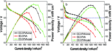 | ||
| Fig. 1 The effect of PVA location in the cathode CL of the self-humidifying MEAs on the cell performance, operated at 60 °C and 30 psi under 100% RH (a) and 20% RH (b) both for anode and cathode. | ||
However, under 15% RH for both anode and cathode at 60 °C, it is clear that the performance of DC-3PVA-inner shows the best cell performance over whole current density range. By adding PVA in the cathode CL, the hygroscopic property of MEA is enhanced greatly and that may enhance the water produced in cathode transported to anode and then wet the membrane. In the low humidifying state, it is particularly important at the low current density. In the case of self-humidifying MEA with addition of PVA in the inner layer, it is expected to that the water concentration gradient between the cathode and anode increased strongly than the other two MEAs. Hence, the self-humidifying performance of DC-3PVA-outer and SC-3PVA is poorer than that of DC-3PVA-inner at such low humidity condition. Therefore, we believe that the enhanced cell performance is attributed to the hygroscopic property of PVA and the greater water concentration gradient between cathode and anode.
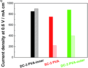
For clarity, we plotted the current density at 0.6 V of the three MEAs with various cathode CL structure, as shown in Fig. 2. At 0.6 V, the current density of DC-3PVA-inner reach up to 900 mA cm−2. In addition, this value is about 4.1 times and 2.25 times to that of SC-3PVA (220 mA cm−2) and DC-3PVA-outer (400 mA cm−2), respectively. The maximum power density of DC-3PVA-inner is 590 mW cm−2. That is because PVA exhibit strong moisturizing capabilities and absorb water, which is not only wetting the inner CL but also enhance the water concentration gradient at low current density under the low humidity condition, resulting keep the Nafion membrane at a good hydration state. May be due to the water concentration gradient at 20% RH increases compared to that at 100% RH, the water is easier to spread to the anode, resulting in the elimination of flooding in the cathode and the decrease of oxygen diffusion resistance. Hence, it can be observed that the current density at 20% RH is slightly higher than that at 100% RH. From these results, it is believed that the induction of PVA in the inner layer of dual cathode CL structure is a viable approach for preparation of self-humidifying MEA.
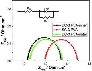
To understand the performances of MEAs with different cathode structure under 100% humidification, the electrochemical impedance spectra has been measured at 0.8 V. Fig. 3 shows the in situ impedance curves and equivalent circuit (inset) of the home-made MEAs. In the equivalent circuit, RΩ represents the total ohmic resistance of the cell which includes the ohmic resistances of the membrane and the contact resistances between various cell components. Rct is usually associated with the charge transfer resistance across the catalyst/electrolyte interface.1,4 By adding PVA in the cathode CL, the ohmic resistance increase due to the non-conductivity of PVA, compared to the previous articles.16,17 From Table 2, it is observed that the MEA (DC-3PVA-inner) shows lowest RΩ due to the inner CL will gather more water near the Nafion membrane, result in a higher water concentration gradient between cathode and anode at such high voltage. The amount of water transported from cathode to anode side by back diffusion significantly increased, which is helpful for wetting the Nafion membrane and make it at a good hydration state. In addition, the introduction of PVA in the inner layer, partly Pt catalyst active sites may be covered by PVA, resulting in the highest charge transfer resistance for DC-inner-3PVA.
| MEAs | DC-3PVA-inner | SC-3PVA | DC-3PVA-outer |
|---|---|---|---|
| RΩ (Ω cm2) | 1.041 | 1.199 | 1.061 |
| Rct (Ω cm2) | 0.301 | 0.291 | 0.292 |
Furthermore, we conducted a short-term constant voltage discharge test to determine the stability of the three self-humidifying MEAs, as shown in Fig. 4. The test was performed at 60 °C and under 20% RH both for anode and cathode. It can be observed that the performance of SC-3PVA declined sharply. The current density of SC-3PVA decreased about 80% within 5 hours. In comparison, for DC-3PVA-outer with adding PVA in the outer layer, the current density float up and down in a large range. This result implies that sometimes the water easily gathered in the more hydrophilic outer layer, impeding gas transport to the active sites of Pt catalyst. On the other hand, the cell cannot ensure the establishment of a large water concentration gradient between the cathode and anode, therefore the anode CL dry up and the cell performance presented unstable.
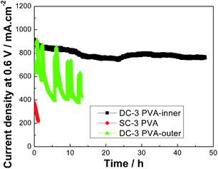 | ||
| Fig. 4 Short-term constant voltage discharge test of the self-humidifying MEAs with different cathode structure at 60 °C and 30 psi under 20% RH. | ||
By contrast, it is clear that the current density of DC-3PVA-inner remained as high as 750 mA cm−2 at 0.6 V after 50 h of testing, indicating the excellent self-humidification performance and stability of this type of MEA. The large difference in performance between these three self-humidifying MEAs indicates the effect of back diffusion of water and proved again that the design by adding of PVA in the inner layer is the key for improving cell performance at a low humidity.
Effect of PVA content
Fig. 5(a) plots the polarization curves and the power outputs of the self-humidifying MEAs with various PVA content in inner layer under the 100% humidified H2 and air condition. It can be obviously seen that the performances of MEAs with adding PVA in the cathode are almost same as that of the blank MEA (DC-0PVA-inner) in low current density region. However, in the high current density area, all the self-humidifying MEAs yielded worse performance compared with the blank MEA, as shown in Fig. 5(a). We speculate that the CL flooded by the water due to the strong water absorption ability of PVA. Meanwhile, it is clearly that the performances of the MEAs with more PVA content in the inner layer (PVA content is 7 wt% and 10 wt%) are much poorer than that of DC-inner-0PVA because too much PVA may cover partly Pt/C that result in the increased of charge transfer resistance and the decrease of the performances. So, we believe that the addition of appropriate amount of PVA is helpful for increasing the water content in the cathode and enhance the water concentration gradient between cathode and anode although the cell performance of self-humidifying MEAs is poorer than that of the blank MEA in the case of full humidity condition.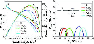 | ||
| Fig. 5 The performances (a) and in situ impedance curves (b) of single cell with adding different content of PVA in the cathode inner layer at 60 °C and 30 psi under completely humidified. | ||
In order to further understand the effect of the MEA type on the cell performance, the EIS measurements were conducted at cell potential of 0.8 V. Fig. 5(b) shows the in situ impedance curves and Table 3 shows the ohmic resistances and the charge transfer resistances of these MEAs fitted by equivalent circuit. It is clear that in relation to the blank MEA, the ohmic resistance for all of them increases significantly at 100% humidity for anode and cathode due to the non-conductively of PVA in the electrodes. In addition, the ohmic resistance increases gradually with the increasing of PVA content. These results are quite consistent with the performance results, as lager resistance results in poor self-humidification. As the results shown in Table 3, the MEA with 3 wt% PVA in the inner layer has lowest charge transfer resistance, 0.302 Ω cm2. It indicates that 3 wt% is the most suitable PVA adding amount for the cell in both whole humidification.
| MEAs | 0 wt% | 3 wt% | 5 wt% | 7 wt% | 10 wt% |
|---|---|---|---|---|---|
| RΩ (Ω cm2) | 0.970 | 1.041 | 1.233 | 1.626 | 1.825 |
| Rct (Ω cm2) | 0.315 | 0.302 | 0.347 | 0.387 | 0.323 |
We also compared the performance of the four MEAs under 20% RH. As shown in Fig. 6, when the MEAs operated at 20% humidification, the self-humidifying MEA (DC-3PVA-inner) with hydrophilic materials added to the inner layer showed superior performance compared to the blank MEA in the low current density area. We believe that the anode and cathode are in a state of extreme water shortage when the MEA the MEAs operated under low humidity condition. Since the hygroscopic material (PVA) enhances the water-retention capacity of the electrodes, the scant moisture may be locked in the inner layer of the cathode which contact the Nafion membrane. Under the impetus of the water concentration gradient between cathode and anode, the water in the cathode back diffuse to anode and then wet the Nafion membrane, so as to achieve the purpose of self-humidification. However, with the PVA content increasing, the cell performance decreased, which may have resulted from the increase in ohmic resistance due to the addition of non-conductor. In addition, in the high current density area, the self-humidifying MEAs yielded poorer performance compared with the blank MEA due to the cathode easily flooded. Based on the above results, 3 wt% PVA content is considered to be the optimum content in anode CL, which makes the MEA (i.e. DC-3PVA-inner) possesses a lower resistance and better water retention ability simultaneously. For this reason, DC-3PVA-inner was chosen for the following tests.
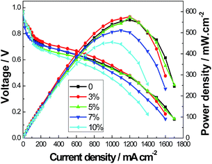 | ||
| Fig. 6 Polarization curves and power outputs of the self-humidifying MEAs with adding different content of PVA in the cathode inner layer at 60 °C and 30 psi under 20% RH. | ||
Effect of various RHs
To further investigate the effects of humidification on the performances, we measured the DC-3PVA-inner at 60 °C and 30 psi under different RH conditions, as shown in Fig. 7. Although decreasing the RH of anode and cathode deteriorate the cell performance in the low current density, there is almost no difference in the concentration polarization region owing to the phenomenon of cathode flooding effectively reduced by RH decreased. This proved once again that adding PVA into inner layer of the dual layer cathode structure is the key to improve the performance of self-humidifying MEA at the low humidity conditions.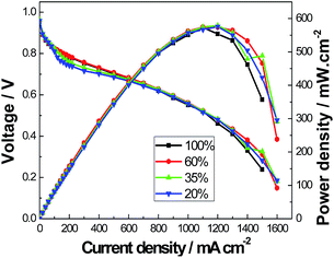 | ||
| Fig. 7 The performances of self-humidifying MEA (DC-3PVA-inner) under different RH both for anode and cathode. | ||
Conclusions
In conclusion, a novel self-humidifying membrane electrode assembly is prepared successfully by adding hydrophilic polymer PVA into the inner layer of the dual cathode CL. This self-humidifying MEA showed excellent self-humidification performance, and the optimum content of PVA in the inner layer is ca. 3 wt%. The current density of MEA (DC-3PVA-inner) at 0.6 V reached 910 mA cm−2 and remained at 750 mA cm−2 after 50 h of short-term testing at 20% RH and 60 °C, revealing its impressive self-humidification properties. It is interesting that the performance of self-humidifying MEA PVA5 is hardly changed even if the RHs of both the anode and cathode decrease from 100% to 20%. The improved self-humidification performance can be attributed to the water absorption properties of PVA in the CL, which enhanced the water back diffused from cathode to anode and though Nafion membrane, resulting in the Nafion membrane maintaining a satisfactory hydration state.Acknowledgements
The authors gratefully acknowledge the Fundamental Research Funds for the Central Universities (Project Number 2014ZDPY20) for financial support of this work.Notes and references
- H. Liang, L. Zheng and S. Liao, Int. J. Hydrogen Energy, 2012, 37, 12860–12867 CrossRef CAS.
- J. Larminie and A. Dicks, Fuel Cell Systems Explained, Wiley, 2nd edn, 2003 Search PubMed.
- H. N. Yang, D. C. Lee, S. H. Park and W. J. Kim, J. Membr. Sci., 2013, 443, 210–218 CrossRef CAS.
- H. Liang, D. Dang, W. Xiong, H. Song and S. Liao, J. Power Sources, 2013, 241, 367–372 CrossRef CAS.
- H. N. Yang, S. H. Cho and W. J. Kim, J. Membr. Sci., 2012, 421–422, 318–326 CrossRef CAS.
- T. Susai, M. Kaneko, K. Nakato, T. Isono, A. Hamada and Y. Miyake, Int. J. Hydrogen Energy, 2001, 26, 631–637 CrossRef CAS.
- T. E. Springer, T. A. Zawodzinski and S. Gottesfeld, J. Electrochem. Soc., 1991, 138, 2334–2342 CrossRef CAS.
- G. J. M. Jannsen and M. L. J. Overvelde, J. Power Sources, 2001, 101, 117–125 CrossRef.
- H. H. Voss, D. P. Wilkinson, P. G. Pickup, M. C. Johnson and V. Basura, Electrochim. Acta, 1995, 40, 321–328 CrossRef CAS.
- E. D. Wang, P. F. Shi and C. Y. Du, J. Power Sources, 2008, 175, 183–188 CrossRef CAS.
- Z. Miao, H. Yu, W. Song, D. Zhao, L. Hao, B. Yi and Z. Shao, Electrochem. Commun., 2009, 11, 787–790 CrossRef CAS.
- X.-G. Yang, N. Burke, C.-Y. Wang, K. Tajiri and K. Shinohara, J. Electrochem. Soc., 2005, 152, A759–A766 CrossRef CAS.
- C.-Y. Wang, Chem. Rev., 2004, 104, 4727–4766 CrossRef CAS PubMed.
- V. Senthil Velan, G. Velayutham, N. Hebalkar and K. S. Dhathathreyan, Int. J. Hydrogen Energy, 2011, 36, 14815–14822 CrossRef CAS.
- S. Vengatesan, H.-J. Kim, S.-Y. Lee, E. Cho, H. Yong Ha, I.-H. Oh, S.-A. Hong and T.-H. Lim, Int. J. Hydrogen Energy, 2008, 33, 171–178 CrossRef CAS.
- B. T. Zhao, L. L. Sun, R. Ran and Z. P. Shao, Solid State Ionics, 2014, 262, 313–318 CrossRef CAS.
- H. N. Su, S. J. Liao and Y. N. Wu, J. Power Sources, 2010, 195, 3477–3480 CrossRef CAS.
- C. Y. Jung, T. H. Kim and S. C. Yi, ChemSusChem, 2014, 7, 466–473 CrossRef CAS PubMed.
- X. Leimin, L. Shijun, Y. Lijun and L. Zhenxing, Fuel Cells, 2009, 9, 101–105 CrossRef CAS.
- H.-N. Su, Q. Zeng, S.-J. Liao and Y.-N. Wu, Int. J. Hydrogen Energy, 2010, 35, 10430–10436 CrossRef CAS.
- K. H. Kim, H. J. Kim, K. Y. Lee, J. H. Jang, S. Y. Lee, E. Cho, I. H. Oh and T. H. Lim, Int. J. Hydrogen Energy, 2008, 33, 2783–2789 CrossRef CAS.
| This journal is © The Royal Society of Chemistry 2016 |

