DOI:
10.1039/C5RA19763E
(Paper)
RSC Adv., 2016,
6, 12315-12325
Structural and spectroscopic studies of iodine dimer radical anion hydrated clusters: an approach using a combination of stochastic and quantum chemical methods†
Received
24th September 2015
, Accepted 12th January 2016
First published on 18th January 2016
Abstract
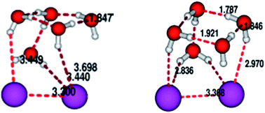
In this communication we would like to explore the idea of obtaining structures and IR spectral features of I2−(H2O)n cluster with n = 2 to 6. The approach taken up by us is a two tire one with initial good quality pre-optimized structures being found out by exploring a suitably constructed empirical potential energy surface and using the stochastic optimizer simulated annealing to explore the surface. These structures are then further refined using quantum chemical calculation to obtain the final structure and the IR spectra. We clearly show that the initial pre-optimization can indeed pave the way for quick and better convergence on subsequent quantum chemical refinement. To give credence to our effort we have also shown the evolutionary trend in vertical detachment energy (VDE) as a function of cluster size.
I. Introduction
The study of water clusters encapsulating ions of different kinds has been a much sought after area of research in the last decade. Both experimentalists and theoreticians have contributed hand in hand to increase the understanding of these cluster systems which in most cases, especially if the coordinated ion is an anion, is stabilised by hydrogen bonding. This stabilising interaction, along with clusters where van der Waals forces play a major role, are energetically less or weaker in comparison to conventional ionic or covalent forces. The renewed and growing interest in this field is principally due to the immense variety of structures supported by a cluster of a given size.1–19,24–26 A moderately sized cluster like six water molecules coordinating with an anion X− can give rise to numerous structures, often differing in small magnitude of energy. Work on X−(H2O)n clusters (with X = F, Cl, Br, I, OH) have already created a large repository of impressive literature.24–26 Both theoretical and experimental works are present and the benchmark experimental data of Mark Johnson27–32 and his group deserves a special mention as these have paved a way for theoreticians to look into these systems in a more insightful manner. These systems are stabilised by hydrogen bonds of two types. Firstly the single hydrogen bond (SHB) which the hydrogen of a water molecule can form with X− and secondly the water–water hydrogen bonded network. Among the halide ions it has already been reported that owing to its small size the F− ion forms clusters where it is totally embedded in the (H2O)n network but the larger halide ions, especially Br− and I− prefer surface capped structures. Since a structure has close relation with spectroscopy, a convenient tool to study these systems is to check the O–H stretching frequencies and how they are modulated by formation of hydrogen bonds. A hydrogen bond will certainly leave its signature on the IR spectrum by generating a red-shifted O–H peak compared to a free O–H stretch. In many cases the magnitude of red shift also changes with change in size of the clusters and these have been well documented in earlier studies.19
We in the present manuscript would like to report theoretical results on I2−(H2O)n clusters using a strategy which is different from the conventional approach used in most cases.19 The iodine dimer radical anion is a more complicated solute than a simple I− when it comes to diversity in the solvated structures with H2O. In these systems there are possibilities of formation of three different types of hydrogen bonding. The SHB and the water–water bond obviously can form but in addition there is a scope of formation of double hydrogen bond (DHB) where two hydrogens from the same H2O molecule coordinates with both the iodines in I2−. Broadly what is reported already is that the negative charge on I2− is distributed equally between the two I atoms and if all three types of hydrogen bonds exist in a structure the water–water hydrogen bonds have a dominant role in dictating the structural form compared to SHB or DHB. The IR spectral peaks have also been assigned for these systems and there are also reports on evaluation of Vertical Detachment Energy (VDE).19 We must stress at this point that nearly all theoretical studies are purely quantum chemical in nature with results reported principally using Density Functional Theory (DFT) with various functionals using different basis sets also i.e. 6-311++G(3df,3pd) and 6-31+G(d,p) and perturbative calculations at the MP2 level of theory using 631+G(d,p) as basis set.
However, we in this present study have adopted a different route to arrive at structures for these systems. It has already been reported in earlier works that there can be an alternative approach to carrying out a quantum chemical calculation from the outset.24,25 This involves the use of empirical potentials to generate good quality initial guess structures and then use these as inputs for subsequent quantum chemical calculations. This approach in most cases guarantees achievement of global minimum and can also be tuned to locate low lying local minima also. To the best of our knowledge the use of well calibrated empirical potentials in halogen dimer radical anion–water clusters have not been attempted and used so far in literature. Once the empirical potential is written down, the next step, which is by no means trivial, is to find the minimum points on these surfaces with obvious emphasis on the global minimum. To achieve this we use stochastic optimization method namely simulated annealing (SA) to meet this goal. SA can be effectively used as a global optimizer and it has a rich history of being used as an effective method in the study of both structure and dynamics in chemistry.33–51 Once SA search on the empirical surface gives us good quality structures, we use these for subsequent quantum chemical calculations to get both the final structures as well as IR spectral peaks and VDE. We compare our result with those existing in literature using other approaches.19 We have used our stochastic + quantum chemical route to study I2−(H2O)n clusters with n = 1–6.
In the following sections we first discuss in detail the methodology used and then present our results of structural and spectroscopic aspects and then conclude the presentation. Before going on to the next sections, we stress that in systems like I2−(H2O)n, since local minima structures are also numerous in number, we have given special emphasis to report local minima as well as the global. Here by global we mean the lowest energy one among those, we have found and these findings are supported by results already existing in literature.35 We have also tried to perform quantum chemical calculations with different functionals and basis sets again to see the degree of success each one achieves in explaining hydrogen bonding.
II. Methodology
A. The empirical potential used
To model the empirical potential energy surface which described the interactions between the I2− ion and the (H2O)n network we have used a combination of Lennard Jones, coulombic and polarization terms. In earlier works on related systems, a combination of these terms have been found adequate to create a good quality potential energy surface.20,21 The potential energy (V) for an instantaneous configuration is given by |
V = VLJ + VCoul + VPol
| (2.1) |
where VLJ describes the Lennard Jones interaction between the two ‘I’ and the ‘O’ atoms of the water molecules. |
 | (2.2) |
r′ij s are the distances between the ith and jth atom and A and B being the Lennard Jones parameters.22–25 However one must keep in mind that there are two sets of A & B parameters, which model the I–O and O–O interactions. The ‘H’ atoms owing to their small size do not enter into the Lennard-Jones summation VLJ. The AO–O, BO–O, AO–I and BO–I parameters are listed in Table 1.22–25
Table 1 Parameters used in empirical potential energy function eqn (2.2)
Interaction type |
A [kcal mol−1 Å12] |
B [kcal mol−1 Å6] |
O–O |
582 000 |
595 |
O–I |
131 183 121.5 |
7243.0 |
The VCoul term contains the interactions between the charges on I, H and O species. The two ‘I’s are assigned charges of
, while the O & H atoms on H2O process charges of −0.86 and +0.43 respectively. This is in accordance with the TIP3P model for H2O developed by Jörgensen.52
|
 | (2.3) |
where
qi and
qj are the respective charges and
rij again being the distance between the charged units given in
Table 2.
22–25
Table 2 Charges and polarizability used in empirical potential energy function eqn (2.3) and (2.5)
Atom type |
q |
α [Å3] |
O |
−0.834 |
1.44 |
H |
0.417 |
— |
I |
0.5 |
6.92 |
A combination of VLJ & VCoul would have been enough for systems where the polarizability of the constituting atoms are low. However, in this case the ‘I’ units are highly polarizable and one expects a significant contribution from polarization forces. The VPol interaction is depicted as
|
 | (2.4) |
with

being the induced dipole moment of the
kth entities (here the
k sites are the ‘I’ units in I
2−) and

denotes the electric field created at
k because of other charges.
Now,
|
 | (2.5) |
and
|
 | (2.6) |
with

and

being the corresponding propagators generated out of Coulomb and dipole interactions. The term
α is the polarizability of ‘I’ unit and the value used is again given in
Table 2.
22–25
It is true the accuracy of the force field is paramount for initial good quantity pre-optimized structure being found out, which will ultimately serve as input for subsequent quantum chemical calculations. In earlier works20,21,24–26 of similar nature where the encapsulated ion is a halide ion the force field used have been combinations of Lennard-Jones, coulombic and polarization effects. We have tried the modelling in a similar line. However, the only issue which needed to be resolve was the magnitude of charge that should be allocated on the individual iodine units in I2(−). Earlier reports on these types of system using quantum chemical calculations indicate that the one unit negative charge should be symmetrically disposed in the two I units. The parameters for the Lennard-Jones interaction and the polarizability contribution have all been taken from values already existing in literature22–25 and have been presented in tabular form. Now the question is how good is this force field? This will be discussed in section Result & discussion and our findings will show that this force field is capable enough to generate good quality candidate structures for subsequent quantum chemical modification. The TIP3P model is not the only water model that is used in this kind of studies. Our philosophy of using the TIP3P potential for the water–water interactions only is based on the fact that even staying within this model good candidate structures can be generated which is clear from our results. Of course it is needless to say that the O–I interactions are all modelled by completely different set of parameters which already exist in literature. A strategy similar to this have been used in earlier reports.20,21,24–26
B. Simulated annealing (SA) and the way to generate structures on the empirical surface
As is clear from the earlier section the magnitude of ‘V’ for an instantaneous geometry is dependent on the r′ij s, which again is dependent on the cartesian coordinates of the atoms in space at a given point. To generate a structure one starts with a guess geometry created by randomly selecting three cartesian coordinates for each atom in the I2−(H2O)n system, so there are 9n + 6 coordinates as each water molecule is described by 9 cartesian coordinates and the I2− unit by 6. These 9n + 6 coordinates are used to find all r′ij s and the starting energy V0 is generated using eqn (2.1).
Now a coordinate is randomly chosen from the set, say ‘x0’. This ‘x0’ is subjected to a random change in one following manner to generate x1.
Here ‘n’ is a random integer, ‘Δ’ is a pre-set magnitude which depicts the maximum amount of change that can happen and ‘r’ is a random integer between 0 & 1. This clearly shows that x0 can be randomly changed both in the positive and negative sense to generate a new coordinate x1. Now with the new coordinate set (where one has been changed from the earlier sequence), the energy of the new configuration V′ is generated. Now we employ SA technique to decide whether the new V′ is acceptable or not. To do this we generate a functional called the costfunctional as follows
where
Vi is the energy of an
ith iteration and
VL is a lower bound to energy which has been supplied.
Now for the initial structure with energy V0, the cost is cost0 and for V′ it becomes cost1. If cost1 < cost0 we accept the move as it signifies a lower energy state has been achieved. If cost1 > cost0, however, we do not discard the move but subject it to the Metropolis Test. In SA there is a temperature like quantity Tat which is used to define a probability of selection (P).
|
 | (2.9) |
where Δcost = cost
1 − cost
0 (difference in cost between two successive moves). With a given value of
Tat, ‘
P’ is calculated. Now a random number ‘
r’ between ‘0’ and ‘1’ is invoked and compared with
P. If
P >
r the move is accepted, otherwise not. It is clear that if
Tat is kept high ‘
P’ will be close to ‘1’ and most moves will pass the Metropolis Sampling Test. When a SA simulation is started
Tat is kept high initially and gradually lowered with successive iterations. The idea being to initially accept moves even if the energy has increased. This is essential because if a structure gets stuck in a high energy minimum it should have the provision to initially go up in energy, surmount any energy barrier and continue its progress towards a deeper minimum close to
VL.
We must emphasize on the point that the cost functional shows in eqn (2.8) can not only search the global minimum but also any higher minimum on the surface. This can be easily done by doing the SA simulation with a higher value of VL. The VL supplied is not a static quantity but can be upgraded or downgraded. Ones we have found a structure close to a certain VL we can dynamically lower it and continue the search for any lower minimum if it exists.
With this strategy we generate several candidate structures for each size of I2−(H2O)n and use these as starting points for subsequent quantum chemical calculations.
C. Quantum chemical calculations
Each structure generated by the earlier outlined procedure is subjected to quantum chemical calculations, both at the DFT level of theory as well as a perturbative one with MP2 being the level. For DFT calculations, we have used two different functionals, namely B3LYP and wB97xD. The basis set used in these calculations being 6-31+G(d,p) with the involvement of Stuttgart effective core potential for iodine. The basis set and core potential for the MP2 calculations used are the same. Once the structures are generated the vibrational peaks are also obtained for each geometry to see the amount of shift generated due to the type of hydrogen bonding (SHB, DHB or water–water). We also try to find out the Vertical Detachment Energy (VDE) for the bare electron where the VDE is defined as the difference in energy between the optimized I2−(H2O)n and the I2(H2O)n (neutral) cluster having the same geometry.
III. Result & discussion
A. Structures of I2−(H2O)n clusters
As we have outlined in the earlier section, our strategy of getting the structures is a two step one, first to generate good pre-optimized structures extremely quickly using SA and the empirical potential energy surface and then follow up with quantum chemical calculations both at the MP2 level using 6-31+G(d,p) as basis set and DFT level (with two different functionals namely B3LYP and wB97xD) using two basis sets 6-311++G(3df,3pd) and 6-311+G(d,p).
1. Structures for n = 2. For this size of the system, we report two low lying structures. The wB97xD functional [using 6-311++G(3df,3pd) as basis set] is seen to be the most successful in producing two isomers with varying structural features. The global minimum structure [Fig. 1(a)] is one with both H2O molecules on the same side of the I2− unit with one H2O molecule having shorter I–H bonds (2.84 Å and 2.92 Å) than the other (3.1 Å). The structure also show one distinct O–H interaction with distance between O & H being 1.97 Å. The energetically highest structure of this size has the two H2O molecules arranged in an exactly anti fashion with respect to the I2 unit [local(1), Fig. 1(b)]. The two isomers from the SA + DFT (wB97xD) are shown in Fig. 1(a) and (b). The SA evaluated structure with closest proximity to the global is depicted in Fig. 1(c). It must be stated that the SA structure shows H–I bond lengths which are higher than the final structures after the quantum chemical calculations. This is not surprising since a full quantum chemical calculation does greater justice in accounting for a more accurate hydrogen bonded interaction than the empirical potential. However it must be appreciated that an initial SA evaluation generates structures which are quite similar in form to the final ones. The structures after MP2 and B3LYP evaluation are shown in the ESI.† The energies of the isomers after SA, B3LYP, wB97xD (using different basis sets, 6-311++G(3df,3pd) and 6-31+G(d,p)) and MP2 (using 6-31+G(d,p) as basis set) estimation are shown in tables in the ESI.† It must be mentioned as a concluding statement that the global minimum structure35 was found out only using the wB97xD functional.
 |
| Fig. 1 Structures for n = 2: (a) & (b) are obtained by SA + quantum chemistry and (c) is obtained by S.A. (where E = energy of the cluster − energy of Global). | |
2. Structures for n = 3. With the increase in the number of water molecules, the possibility of geometries having all the types of interactions, namely DHB, SHB as well as H2O–H2O hydrogen bonds becomes a reality. We have generated five structures for this system. The global minimum [Fig. 2(a)] and two other local among the set are discussed. The global geometry has three SHB between H of three different water molecules and three other O–H⋯O interactions. What is noticeable is the absence of DHB. The next higher local [local(1), Fig. 2(b)] possesses two DHB (between 2.8 to 2.9 Å) and two O–H⋯O interactions (1.98 and 1.98 Å). The highest energy [local(2), Fig. 2(c)], among the three we have evaluated, has a DHB (2.82 and 2.83 Å), one SHB (3.08 Å) and three O–H⋯O interactions (2.01, 2.08 and 2.15 Å). The O–H⋯O interactions are stronger in local(1) than local(2) and that is the reason for local(1) to be energetically stable than local(2). The SA structure which was the pre-optimized input for obtaining the global is shown in [Fig. 2(d)]. The SA structure as in the previous case shows longer H⋯I interaction lengths as opposed to the ones after DFT calculation. All the corresponding structures and energies with different functionals and different basis sets are presented in the ESI† section.
 |
| Fig. 2 Structures for n = 3: (a)–(c) are obtained by SA + quantum chemistry and (d) is obtained by S.A. (where E = energy of the cluster − energy of Global). | |
3. Structures for n = 4. The global structure [Fig. 3] is a highly symmetric one with four H2O units joined to each other with four O–H⋯O bonds on one side of the I2 unit. The four ‘O’ atoms roughly form a square. It is also noteworthy that four additional SHB form from the ‘H’ atoms of four different H2O molecules. The total absence of DHB is worth mentioning. The next higher local structure [local(1), Fig. 3(b)] possesses one DHB interaction, two SHB and four other O–H⋯O bonds. In comparison to the global, the structure has become more asymmetric, though the four H2O units are on one side and are able to interact with each other. To bring out the structural diversity, we now present a high energy local structure [local(8), Fig. 3(c)]. The four H2O molecules can no more interact among them as they are on opposite sides (2 + 2). There are two DHB, two SHB and two O–H⋯O interactions. The increase in the energy of the structures with increase in the number of DHB and decrease in O–H⋯O interactions is once again established. The SA structure [Fig. 2(d)], which led to the generation of the global structure after quantum chemical calculation (at DFT level using wB97xD as functional and 6-311++G(3df,3pd) as basis set) in a similar line possesses the basic interactions of the global in equal proportions but the lengths of the hydrogen bonded interactions are larger as has been the observed trend so far.
 |
| Fig. 3 Structures for n = 4: (a)–(c) are obtained by SA + quantum chemistry and (d) is obtained by S.A. (where E = energy of the cluster − energy of Global). | |
4. Structures for n = 5. With increase in the number of water molecules the number of possible conformers are expected to rise in number. We have located 12 structures for this size (energies given in Table 3). The global geometry is again a highly symmetric one with the presence of one DHB, three SHB and five O–H⋯O interactions. Individual lengths of the bonds are shown in [Fig. 4(a)]. The next higher energy geometry [local(6), Fig. 4(b)] has developed higher asymmetry, with the H2O units now distributed around the I2− unit. The number of DHB's have also increased at the expense of SHB and O–H⋯O interactions. An even higher minimum [local(7), Fig. 4(c)] possesses features in a similar line with further increase in number of DHB's. The SA structure [Fig. 4(d)] which served as input to generate the global minimum has gross features which correspond with the global geometry, i.e., the presence of one DHB, three SHB and four O–H⋯O interactions. As with the other sizes, the ESI† shows structures arrived at by doing quantum chemical calculation following different routes and tables in the ESI† contain the energy values.
Table 3 Relative energy values obtained for different structures of I2−(H2O)n in kcal mol−1, where global structure is selected on the basis at DFT level using wB97XD functional and 6-311++G(3df,3pd) basis set and all the energies are relative taking 0.0 for the lowest energy structure in each case (* marked structures are discussed in details in Section III A)
Cluster |
I2−(H2O)2 (kcal mol−1) |
I2−(H2O)3 (kcal mol−1) |
I2−(H2O)4 (kcal mol−1) |
I2−(H2O)5 (kcal mol−1) |
I2−(H2O)6 (kcal mol−1) |
Global |
0.0* |
0.0* |
0.0* |
0.0* |
0.0* |
local(1) |
1.78540* |
1.48195* |
2.10872* |
0.64997 |
2.42592 |
local(2) |
|
3.13550* |
4.33247 |
3.39997 |
4.30912* |
local(3) |
|
4.92180 |
5.96699 |
4.49372 |
4.36116 |
local(4) |
|
6.62609 |
7.78718 |
7.29060 |
6.61484* |
local(5) |
|
|
7.81450 |
7.29060 |
6.84069 |
local(6) |
|
|
9.06920 |
9.79060* |
9.41137 |
local(7) |
|
|
9.15716 |
9.94685* |
10.93154 |
local(8) |
|
|
9.45114* |
10.91560 |
|
local(9) |
|
|
13.79539 |
10.96248 |
|
local(10) |
|
|
|
12.25935 |
|
local(11) |
|
|
|
13.13435 |
|
 |
| Fig. 4 Structures for n = 5: (a)–(c) are obtained by SA + quantum chemistry and (d) is obtained by S.A. (where E = energy of the cluster − energy of Global). | |
5. Structures for n = 6. The last size we discuss is the one with six H2O molecules coordinating the I2− unit. Eight structures have been generated following the outlined strategy. Table 3 contains the energies. From the eight we have picked up three for discussion. The global geometry [Fig. 5(a)] has a single DHB, three SHB and six O–H⋯O interactions among H2O molecules. The DHB is not totally symmetric with the I⋯H lengths being 2.83 Å and 2.93 Å. The next higher local [local(3), Fig. 5(b)] shows same number of DHB (1) but lesser O–H⋯O interactions (5). The even higher local [local(5), Fig. 5(c)] shows features in a similar line with the number of O–H⋯O interactions being lesser (4) than other two geometry. The SA structure which ultimately served as input for obtaining the global has individual type interaction numbers the same as the global geometry [Fig. 5(d)].
 |
| Fig. 5 Structures for n = 6: (a)–(c) are obtained by SA + quantum chemistry and (d) is obtained by S.A. (where E = energy of the cluster − energy of Global). | |
The above discussion entirely is based on calculations at DFT level using the wB97xD functional and 6-311++G(3df,3pd) basis set. However we have presented structural results with B3LYP and MP2 calculations using different basis sets in the ESI.† Especially it must be noted that for I2−(H2O)2, B3LYP and MP2 calculation failed to locate the global geometry.35 We can compare the results of our effort with a study on the similar system, although using a different procedural route than ours. D. K. Maity reported35 global minimum structures for I2−(H2O)n for various sizes using a DFT calculation with BHHLYP functional and 6-311+G(d,p). For n = 2, 3, 4 the structures reported by us as global perfectly matches with that study. For n = 5 and 6 we have been able to generate lower energy structure than those reported. However, it must be emphasized that a huge number of possible structures within a narrow energy range exist for this system and the global reported by D. K. Maity are also found out in our study but these appear as the second highest local minimum [local(2) and local(2)] for both the sizes.
 |
| Fig. 6 I.R. spectrum of each global structure, calculated at DFT level using wB97xD functional, discussed in detail in Section III B. | |
B. Infra-red spectroscopic features
We now discuss the O–H spectral features of the global structures discussed in the calculations using the wB97xD functional. The peak positions are listed in Table 4 and shown in Fig. 6. However in the ESI† we have provided the spectral positions of all the isomers obtained with both the B3LYP and wB97xD functionals as well as the MP2 method.
Table 4 I.R. peak values (in cm−1) of structures discussed in Section III B
Global structure |
Peaks (cm−1) |
I2−(H2O)2 |
3734.9228, 3788.9154, 3839.1936, 3887.4027 |
I2−(H2O)3 |
3647.5111, 3709.2919, 3725.8870, 3802.0896, 3817.5227, 3832.3595 |
I2−(H2O)4 |
3511.8229, 3580.3992, 3597.2168, 3625.8853, 3826.6102, 3829.1223, 3837.7481, 3846.6147 |
I2−(H2O)5 |
3459.5031, 3559.8376, 3592.8454, 3625.2865, 3703.7902, 3795.0131, 3824.6151, 3844.6304, 3846.3871, 3872.8105 |
I2−(H2O)6 |
3380.6808, 3463.4717, 3542.4176, 3594.3515, 3633.1213, 3698.5868, 3790.2676, 3818.3911, 3825.2260, 3832.8031, 3848.3849, 3941.5773 |
Table 5 Vertical detachment energies obtained for different structures of I2−(H2O)n in kcal mol−1, calculation is carried out on the basis at DFT level using wB97XD functional and 6-311++G(3df,3pd) basis set
Cluster |
I2−(H2O)2 (kcal mol−1) |
I2−(H2O)3 (kcal mol−1) |
I2−(H2O)4 (kcal mol−1) |
I2−(H2O)5 (kcal mol−1) |
I2−(H2O)6 (kcal mol−1) |
Global |
113.86073 |
116.43916 |
120.18334 |
127.22521 |
128.30233 |
We must tress on the point that the IR spectral peaks that we have reported are strictly for the global or the lowest energy configuration found by our strategy. So the report is strictly for a single geometry and does not include the effects of averaging over all accessible configurations within a given energy range. However, if one wishes to get this structural features for a given temperature then one can use the Boltzmann statistical weights at a particular temperature. However, in the limit of the temperature becoming very low the system is expected to be predominantly in the lowest energy state.
Table 6 Comparison of stretching frequencies with earlier reported work.35
n for I2(−)(H2O)n |
Structure |
Calculated |
Calculated in earlier work |
2 |
Global |
3734.9228 |
3836.9565 |
3788.9154 |
3900.0000 |
3839.1936 |
3951.0869 |
3887.4027 |
4014.1304 |
3 |
Global |
3647.5111 |
3778.2608 |
3709.2919 |
3833.6956 |
3725.8870 |
3847.8260 |
3802.0896 |
3910.8695 |
3817.5227 |
3945.6521 |
3832.3595 |
3956.5217 |
4 |
Global |
3511.8229 |
3679.3478 |
3580.3992 |
3730.4347 |
3597.2168 |
3754.3478 |
3625.8853 |
3773.9130 |
3826.6102 |
3943.4782 |
3829.1223 |
3945.6521 |
3837.7481 |
3954.3478 |
3846.6147 |
3960.8695 |
1. IR features for I2−(H2O)2. The global minimum structures shows four stretching peaks at 3887.40, 3839.19, 3788.91 and 3734.92 cm−1 respectively. The first two are principally asymmetric stretching of the individual water molecules. The last two peaks are a result of co-operative motion of both H2O molecules and much more intense than the first two. For the peak at 3788.91 cm−1, while both the –O–H in one H2O are elongated, the –O–H bonds of the other are shortened. The most intense among the peaks is at 3734.92 cm−1 and in this both the –OH bonds in both molecules are simultaneously elongated and shortened.
2. IR features for I2−(H2O)3. The stretching peak positions are at 3647.51, 3709.29, 3725.88, 3802.08, 3817.52 and 3832.35 cm−1. The peak at 3832.36 cm−1 is of significant intensity (479 units) and is due to all the three water molecules exhibiting asymmetric stretching individually. The next two peaks 3817.51 and 3802.08 are in a similar line with the amount of stretching contribution from the individual water molecules being dissimilar. The significantly intense peak is at 3725.88 cm−1 (304 units) and is clearly due to some amount of –O–H⋯O hydrogen bonding. The peaks at 3709.29 and 3647.51 are also due to stretches being modulated by H-bonding with the 3647.51 cm−1 peak very clearly displaying hydrogen bonded features.
3. IR features for I2−(H2O)4. The stretching peaks for the global minimum in this system occur at 3846.61, 3837.74, 3829.12, 3826.61, 3625.88, 3597.21, 3580.39 and 3511.82 cm−1 respectively. The most intense peaks are 3580 and 3597 cm−1 with the intensity values being 639 and 822 units respectively. The peak at 3597 shows the clear presence of two –O–H⋯O vibrations taking place simultaneously. The other peak is also in a similar line with slight modulations due to all of four O–H⋯I stretching also. The peaks above 3800 cm−1 do not contain the features of –O–H⋯O vibrations but are co-operative individual O–H motions directed towards and away from the I2− core.
4. IR features for I2−(H2O)5. The global minimum for this size shows about 10 stretching vibrations at 3872.81, 3846.39, 3844.63, 3824.62, 3795.01, 3703.79, 3625.29, 3592.85, 3559.84 and 3459.50 cm−1. The peaks above 3800 cm−1 are relatively less in intensity with the significant one being at 3862 cm−1 with an intensity of 178 units. This peak involves principally the asymmetric motion of one H2O unit with the others contributing to a lesser degree, and the –O–H motion is directed towards the I2− core. The most intense peak is at 3592.85 cm−1 with an intensity of 810 units. There are three individual O–H⋯H contributions, which is the cause for the strong intensity. The peaks at 3559.84 and 3459.50 cm−1 are also significant and sufficiently red shifted hydrogen bonded ones with intensities of 444 and 249 units respectively. At this point it is worth noting the appearance of stronger red shifted peaks as we increase the cluster size from 2 to 5 water molecules. This is in an expected line.
5. IR features for I2−(H2O)6. The lowest energy geometry for this size displays 12 stretching vibrations at 3941.58, 3848.38, 3832.80, 3825.23, 3818.39, 3790.27, 3698.59, 3633.12, 3594.35, 3542.42, 3463.47 and 3380.68 cm−1. The intense peaks are mostly less than 3800 cm−1 at 3380.68, 3463.47, 3542.42, 3594.35, 3633.12, 3698.59 cm−1 with intensity 600, 518, 739, 399, 339, 329 units respectively. These are all due to cooperative effects of a number of individual O–H⋯O stretches being as high as four for the 3542 cm−1 peak. The higher stretches are mostly due to contributions from few H2O molecules with the 3941.58 cm−1 peak clearly being a result of a single H2O molecule exhibiting asymmetric stretch.So we can conclude that the general trend of getting more intense and significantly red shifted peaks increases as we increase the size of the clusters from two H2O molecules to six H2O molecules.
Having discussed the IR spectral features of the cluster system, it must be mentioned that in a real experimental scenario at a finite temperature, the actual spectrum observed will have contributions from the local minima in addition to the global. However if the experimental temperature is lowered and in the limit of it becoming very low the contribution from the global minimum will be the one which will survive. This is obvious since if we invoke the concept of Boltzmann's weights which describes the probability of a particular conformer being actually sensed, at higher temperatures the greater will be contributions from high energy structures and vice versa.
Comparison of stretching frequencies with earlier reported works35. As we have already mentioned our global structure corresponds to the global from this earlier work only for n = 2, 3 and 4, for n = 5 and 6 we have been able to locate deeper minima. Though our calculations are with a different basis set and also a different functional. There is a general correspondence of the number of peaks obtained above 3000 wave number for n = 2, 3 and 4, tabulated in Table 6. The number of peaks are respectively four, six and eight. The general trend is that our peaks are slightly blue shifted with respect to the earlier work. However, it goes without saying that a choice of a scaling factor can reduce these differences which exists but it is not expected that a calculation with different basis set and functional should be reproduce exactly similar values. However the similarity in the number of peaks obtained is a testimony of the fact that the global structures are similar at least for these sizes.
C. Variation in vertical detachment energy (VDE) of I2−(H2O)n clusters
The VDE of a system is defined as the difference in energy between the optimized structure and the structure devoid of a single electron having the same geometry. So, for a given size, the VDE is represented as |
VDE(n) = EI2(H2O)n − EI2−(H2O)n
| (3.1) |
We have plotted the variation in VDE for different ‘n’ as a function of ‘n’ in Fig. 7 and the values are listed in Table 5. The trend is an interesting one and can be explained from the variation in structural features and especially the number of hydrogen bonded interactions, that a given size cluster possesses. We must also emphasize that this plot is generated by considering only the global structures for each size. As one goes on increasing ‘n’ from 2 to 5, one notices a steady increase in VDE. This can be explained taking into account the gradual increase in the number of hydrogen bonded interactions between the O–H and the I2− units as one increases the size ‘n’ from 2 to 5. This feature is clearly established in Fig. 1–5. As the number of hydrogen bonded interactions increase, so does the stability of the cluster of a given size. The excess negative charge on the I2− unit participate in the hydrogen bonding and gets strongly held in the hydrogen bonded motifs. As the stability increases, so does the energy needed to knock off an electron from a cluster. However this comforting trend somehow gets disturbed as one goes from n = 5 to n = 6. The VDE at this point increases only slightly and shows signs of saturating. This can again be explained from the global minimum structure of I2−(H2O)6 [Fig. 5(a)]. The sixth H2O unit is accommodated at a large distance from the I2− motif and fails to engage in hydrogen bonding with the I2− but rather engages in hydrogen bonding with other H2O units. So the energy for knocking off the electron from I2−(H2O)6 is not much high as compared to I2−(H2O)5. Only the near neighbour interactions have significant effect in controlling the VDE.
 |
| Fig. 7 Vertical detachment energy (VDE) for global structures of each cluster size (n), discussed in detail in Section III C. | |
IV. Conclusion
We have shown how a suitable empirical potential energy surface of reasonably good quality can be constructed for systems to which the centrally solvated ion is an open shell one. The structure supported by this empirical surface in most cases are not far of from the final ones obtained after the quantum chemical calculation. In most cases the global structures on the empirical surface is able to generate the global structure even after quantum chemical calculation with a few exceptions which we have clearly shown. The shifts in the IR spectrum on account of H-bonding is also exhaustively discussed with elaborate data being provided even for local isomers. As these clusters support large number of minima, we have given due consideration in generating most of them. The vertical detachment energy is also a property worth looking into and we have found a very interesting trend of the VDE showing a steady increase upto the size of n = 5 and then gradually saturating at n = 6 which can be explained from the features of cluster structures.
Acknowledgements
P. N. wants to thank C.S.I.R.,New Delhi, India for the award of a Junior Research Fellowship [09/028(0938)/2014-EMR-I] and P. C. sincerely acknowledges U.G.C.,New Delhi, India for a major research project.
References
- W. H. Robertson, E. G. Diken, E. A. Price, J. W. Shin and M. A. Johnson, Science, 2003, 299, 1367–1372 CrossRef CAS PubMed.
- J. M. Weber, J. A. Kelley, S. B. Nielson, P. Ayotte and M. A. Johnson, Science, 2000, 287, 2461–2463 CrossRef CAS PubMed.
- E. A. Price, N. I. Hammeer and M. A. Johnson, J. Phys. Chem. A, 2004, 108, 3910–3915 CrossRef CAS.
- A. K. Pathak, T. Mukherjee and D. K. Maity, Chem. Phys. Lett., 2008, 454, 17–23 CrossRef CAS.
- A. K. Pathak, T. Mukherjee and D. K. Maity, J. Chem. Phys., 2007, 127, 044304 CrossRef CAS PubMed.
- C.-G. Zhan and D. A. Dixon, J. Phys. Chem. A, 2002, 106, 9737–9744 CrossRef CAS.
- X. B. Wang, X. Yang, J. B. Nicholas and L.-S. Wang, Science, 2001, 294, 1322–1325 CrossRef CAS PubMed.
- R. Ayala, J. M. Martinez, R. R. Pappalardo and E. S. Marcos, J. Chem. Phys., 2003, 119, 9538–9548 CrossRef CAS.
- M. Masamura, J. Chem. Phys., 2003, 118, 6336–6347 CrossRef CAS.
- S. J. Vaughn, E. V. Akhmatskaya, M. A. Vincent, A. J. Masters and I. H. Hillier, J. Chem. Phys., 1999, 110, 4338–4346 CrossRef CAS.
- C.-G. Zhan, F. Zheng and D. A. Dixon, J. Chem. Phys., 2003, 119, 781–793 CrossRef CAS.
- S. S. Xantheas, J. Am. Chem. Soc., 1995, 117, 10373–10380 CrossRef CAS.
- O. T. Ehrler and D. M. Neumark, Acc. Chem. Res., 2009, 42, 769–777 CrossRef CAS PubMed.
- L. Lehr, M. T. Zannai, C. Frischkorn, R. Weinkauf and D. M. Neumark, Science, 1999, 284, 635–638 CrossRef CAS PubMed.
- H. Y. Chen and W.-S. Shew, J. Am. Chem. Soc., 2000, 122, 7534–7542 CrossRef CAS.
- H. Gai, G. K. Schenter, L. X. Dang and B. C. Garret, J. Chem. Phys., 1996, 105, 8835–8841 CrossRef CAS.
- G. Markovich, S. Pollac, R. Giniger and O. Cheshnovosky, J. Chem. Phys., 1994, 101, 9344–9353 CrossRef CAS.
- B. Brada, P. C. Hiberty and A. Savin, J. Phys. Chem. A, 1998, 102, 7872–7877 CrossRef.
- D. K. Maity, J. Phys. Chem. A, 2002, 106, 5716–5721 CrossRef CAS.
- S. G. Neogi and P. Chaudhury, Mol. Phys., 2015, 113, 3729–3739 CrossRef CAS.
- S. G. Neogi and P. Chaudhury, J. Comput. Chem., 2014, 35, 51–61 CrossRef PubMed.
- L. X. Dang, J. Chem. Phys., 1999, 110, 1526–1532 CrossRef CAS.
- W. Murphy, J. Chem. Phys., 1977, 67, 5877 CrossRef CAS.
- S. G. Neogi and P. Chaudhury, J. Comput. Chem., 2012, 33, 629–639 CrossRef CAS PubMed.
- S. G. Neogi and P. Chaudhury, J. Comput. Chem., 2013, 34, 471–491 CrossRef CAS PubMed.
- S. Guha, S. G. Neogi and P. Chaudhury, J. Chem. Sci., 2014, 126, 659–675 CrossRef CAS.
- S. Horvath, A. B. McCoy, B. M. Elliott, G. H. Weddle, J. R. Roscioli and M. A. Johnson, J. Phys. Chem. A, 2010, 114, 1556–1568 CrossRef CAS PubMed.
- A. B. McCoy, E. G. Diken and M. A. Johnson, J. Phys. Chem. A, 2009, 113, 7346–7352 CrossRef CAS PubMed.
- S. Horvath, A. B. McCoy, J. R. Roscioli and M. A. Johnson, J. Phys. Chem. A, 2008, 112, 12337–12344 CrossRef CAS PubMed.
- J. R. Roscioli, E. G. Diken, M. A. Johnson, S. Horvath and A. B. McCoy, J. Phys. Chem. A, 2006, 110, 4943–4952 CrossRef CAS PubMed.
- E. A. Price, N. I. Hammer and M. A. Johnson, J. Phys. Chem. A, 2004, 108, 3910–3915 CrossRef CAS.
- W. H. Robertson, E. G. Diken, E. A. Price, J. W. Shin and M. A. Johnson, Science, 2003, 299, 1367–1372 CrossRef CAS PubMed.
- S. Kirkpatrick, C. D. Gelatt and M. P. Vecchi, Science, 1983, 220, 671–680 CAS.
- S. Kirkpatrick, J. Stat. Phys., 1984, 34, 975–986 CrossRef.
- A. K. Pathak, T. Mukherjee and D. K. Maity, ChemPhysChem, 2010, 11, 220–228 CrossRef CAS PubMed.
- S. K. Biring, R. Sharma, R. Misra and P. Chaudhury, J. Clus. Sci., 2013, 24, 715–737 CrossRef CAS.
- S. Talukder, S. Sen, R. Sharma, S. K. Banik and P. Chaudhury, Chem. Phys., 2014, 431, 5–14 CrossRef.
- S. K. Biring, R. Sharma and P. Chaudhury, J. Math. Chem., 2014, 52, 368–397 CrossRef CAS.
- S. K. Biring and P. Chaudhury, Chem. Phys., 2012, 400, 198–206 CrossRef CAS.
- S. Ghosh, S. Talukder, S. Sen and P. Chaudhury, Chem. Phys., 2013, 425, 73–79 CrossRef CAS.
- B. K. Shandilya, S. Sen, T. Sahoo, S. Talukder, P. Chaudhury and S. Adhikari, J. Chem. Phys., 2013, 139, 034310 CrossRef PubMed.
- S. Sen, S. Talukder and P. Chaudhury, Indian J. Phys., 2013, 87, 865–872 CrossRef CAS.
- R. Caputo, A. Kupczak, W. Sikora and A. Tekin, Phys. Chem. Chem. Phys., 2013, 15, 1471–1480 RSC.
- P. N. Samanta and K. K. Das, Comput. Theor. Chem., 2012, 1000, 42–51 CrossRef CAS.
- E. D. Glendening and A. M. Halpern, J. Chem. Educ., 2012, 89, 1515–1521 CAS.
- D. Gottstein, D. K. Kirchner and P. Guentert, J. Bio. NMR, 2012, 52, 351–364 CrossRef CAS PubMed.
- B. Lu, Z. Guo, L. Wang and J. Zhao, J. Comp. Theor. Nanosci., 2011, 8, 2488–2491 CrossRef CAS.
- L. Wang and D. Xie, Chin. J. Chem. Phys., 2011, 24, 620–624 CrossRef CAS.
- R. Q. Topper, W. V. Feldmann, I. M. Markus, D. Bergin and P. R. Sweeney, J. Phys. Chem. A, 2011, 115, 10423–10432 CrossRef CAS PubMed.
- A. T. Al-Motasem, M. Posselt, F. Bergner, U. Birkenheuer and A. Tekin, J. Nucl. Mater., 2011, 414, 161–168 CrossRef CAS.
- Y. K. Vermani and R. K. Puri, Cent. Eur. J. Phys., 2011, 9, 621–627 CAS.
- W. L. Jorgensen, J. Chandrasekhar, J. D. Madura, R. W. Impey and M. L. Klein, J. Chem. Phys., 1983, 79, 926 CrossRef CAS.
Footnote |
† Electronic supplementary information (ESI) available. See DOI: 10.1039/c5ra19763e |
|
This journal is © The Royal Society of Chemistry 2016 |
Click here to see how this site uses Cookies. View our privacy policy here.