Mesoporous Au nanotube-constructed three-dimensional films with excellent SERS performance based on the nanofiber template-displacement reaction strategy

Hui He*a, Kai Lia, Jing Donga, Jie Xiaa, Yi Zhanga, Tonghui Yanga, Xinli Zhaoa, Qingli Huangb and Xianghua Zeng*a
aCollege of Physics Science and Technology, Yangzhou University, Yangzhou 225002, P. R. China. E-mail: huihe@yzu.edu.cn; xhzeng@yzu.edu.cn
bTesting Center, Yangzhou University, Yangzhou City, Jiangsu 225009, China

Received 23rd September 2015 , Accepted 22nd December 2015

First published on 28th December 2015


Abstract

A facile and high-throughput strategy is presented to fabricate three-dimensional hierarchically porous Au films with good flexibility and transferability via displacement reaction of a Ag-coated electrospun nanofiber template. The films are constructed by mesoporous Au nanotubes, homogeneous in the macroscale but rough and porous in the nanoscale. Each nanotube-block is micro/nanostructured with evenly distributed mesopores on the tubewalls. Further experiments have revealed that the Ag sputtering time and displacement reaction conditions are the key influential factors determining the film architecture. Such structured film has exhibited significant surface-enhanced Raman scattering activity with good stability and reproducibility and shown the possibility of molecule-level detection. Additionally, the strategy is general for fabricating other hierarchically porous Au films, such as mesoporous Au hollow sphere arrays.

1. Introduction

Porous Au films have received considerable attention recently owing to their outstanding properties and potential applications in catalysis,1 biosensors,2 fuel cells,3 etc. Especially, they are excellent substrates for surface-enhanced Raman scattering (SERS) sensors by virtue of their good chemical/thermal stability, large surface area to adsorb detected molecules and high density of hot spots.4,5 Several fabrication methods have been developed, including electrodeposition,6 chemical reduction,7 selective etching,8 thermal decomposition,9 sacrificial template routes (colloidal crystal10 and graphene sheets11), etc. Additionally, we have fabricated Au nanochain-built 3D netlike porous films based on laser ablation in water and electrophoretic deposition12 and Au nanoparticle-built mesoporous films based on co-electrophoresis deposition and selective etching.13 However, these techniques still remain short to either control the architecture of Au films or tune the size of nanopores, which are both of importance for practical applications. To date, fabrication of porous Au nanostructures via various established processes has become quite accessible. If these porous nanostructures are utilized as blocks to construct 3D Au films in a controllable way according to needs, it will be completely different. Such porous block-built 3D films would be controllable and tunable in structure and hence in performance. To our knowledge, however, there is few reports on fabrication of such films.

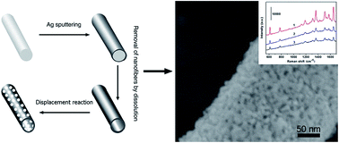
Here we present a green and simple way to build the 3D porous Au films with tunable structures based on a nanofiber template-displacement reaction strategy, as schematically illustrated in Fig. 1. First, the electrospun polystyrene nanofibers (PNs) were coated with Ag by ion beam sputtering, and subsequently removed by dissolution. The Ag nanotubes were thus left. Second, displacement reaction was performed in the Ag nanotube-packed films. Finally, the 3D porous Au films with good flexibility and transferability were thus obtained after cleaning. The films are constructed by Au mesoporous nanotubes, homogeneous in the macroscale but rough and porous in the nanoscale. Each nanotube-block is micro/nanostructured with evenly distributed mesopores on the tubewalls. Such hierarchically porous film could be very useful such as in catalysis, sensors and flexible and transparent nanodevices. It has exhibited significant SERS activity and shown the possibility of molecule-level detection. Also, this strategy is general for fabricating other hierarchically porous Au films, such as mesoporous Au hollow sphere arrays.


image file: c5ra19704j-f1.tif
Fig. 1 Schematic illustration of the strategy for fabricating mesoporous Au nanotubes.

2. Experimental section

2.1. Synthesis of polystyrene nanofibers

Polystyrene (homopolymer, MW = 220[thin space (1/6-em)]000) was dissolved in dimethylformamide with stirring for 6 h to form a 25 wt% transparent solution. About 4 mL of such solution was placed in a syringe equipped with a blunt metal needle of 0.7 mm in hole-diameter. The syringe was placed in a pump that maintained a solution feed rate of 0.5 mL h−1. A stainless steel drum covered with a sheet of Al foil was used as the collector, fixed at about 200 rpm. The distance between the needle tip and the collector was 25 cm, and the voltage was set at 20 kV. The final nanofiber packed film, with white color, was of several centimeters in size and about 20 μm in thickness.

2.2. Ag deposition

Ag was deposited or coated on the electrospun nanofiber films using a commercial ion beam sputtering system at a pressure of 7.5 × 10⁻⁵ Torr. Ar was used as shielding gas. Acceleration voltage was 1.2 kV and ion current was 2.5 mA. The deposition rate was about 0.1 nm s−1 and the coating thickness was controlled by sputtering time. After deposition, the inner PNs were removed by dissolution in CH2Cl2 solution with ultrasonic vibration. The Ag nanotube packed films were thus obtained. For reference, a 2D Ag thin film was also prepared on a Si wafer without the PNs under the same sputtering conditions.

2.3. Displacement reaction and characterization

The Ag nanotube packed films and the corresponding 2D thin film were immersed into 200 mL aqueous solution containing NaCl (2 M), followed by introduction of HAuCl4 (2 mM in the mixed solution). The liquid phase was vigorously stirred with a magnetic stirrer during reaction. The reaction lasts 10 h at room temperature to completely dissolve the Ag nanotubes, and finally deep yellow films were obtained. They are cleaned with deionized water before characterization.

The samples were examined by field-emission scanning electron microscope (FESEM, Sirion 200) and transmission electronic microscope (TEM, JEM-200CX). The size distributions were acquired by measurement of more than 100 in count from FESEM images using Photoshop software. Optical absorption spectra were recorded on a Cary 5E UV-vis-NIR spectrophotometer from wavelengths of 200 to 1200 nm.

For SERS spectral examination, 10 μL R6G aqueous solution was dispersed on the samples at different concentrations and dried in the air. SERS spectra were measured by using a confocal microprobe Raman spectrometer (JY, LABRAM-HR, France) with a 785 nm Ar ion laser line, where the effective power of the laser source was 1 mW. The laser spot focused on the sample surface was about 10 μm in diameter.

3. Results and discussion

Fig. 2a shows a typical morphology of PNs by electrospinning, which are randomly arranged and form a loose film. The PNs are of 300 nm in mean diameter and a narrow size distribution. After Ag coating by ion beam sputtering on the PNs and removal of them, a homogeneous film several centimeters large was obtained on Al foil, as shown in the inset of Fig. 2a (photo of the film). XRD shows that the obtained film is Ag with a fcc structure (Fig. S1). Typically, Fig. 2b shows the morphology of the product by Ag sputtering for 15 min (about 90 nm in thickness) and removal of PNs. Clearly, relative to the original PNs, these Ag nanofibers, which are composed of compacted nanoparticles with sizes of tens of nanometers (inset in Fig. 2b), become thicker because of the coated Ag shells but are still well separated from each other. FESEM image of the fibrous end parts reveals that they are tubularly structured, as shown in Fig. S2, due to ion sputtering induced nonshadow deposition.
image file: c5ra19704j-f2.tif
Fig. 2 FESEM images of electrospun polystyrene nanofiber-film before (a), and after Ag coating (15 min-Ag-sputtering) and subsequent removal of the nanofibers (b). Inset in (a): a photo corresponding to (b). Inset in (b): a local magnified view.

It is worth noting that Ag shell is slightly thicker near top part of the film than elsewhere due to different accessibility of the sputtered Ag atoms/clusters to different places. If the loose PN template (controlled by the preliminary electrospinning durations) is too thick (e.g., >20 μm), however, the Ag shell at the lowest position of the film could be discontinuous. These discontinuous coatings could be removed during subsequent removal of PNs by ultrasonic vibration, and thus the final nanotube built film would be thinner than the original one.

3.1. Morphologies and structure

After displacement reaction of the Ag nanotube built film in 2 mM HAuCl4 aqueous solution containing 2 M NaCl for 10 h, numerous mesopores are formed on tube walls, as shown in Fig. 3a. The sample is uniform over the centimeter scale due to good fluidity of the reaction solution among the gaps between Ag nanotubes. All the nanotubes retain fibrous profile without distortion. The mesopores are through and irregular, and of sub-20 nanometers in scale (Fig. 3b). Further, TEM examination, by strong ultrasonic dispersion of the film in ethanol, shows that the nanotubes are composed of hollow nanoparticles with smaller mesopores (several nanometers in size, unobservable by SEM) in the shells, as seen in Fig. 3c and S3. Overall, such mesoporous Au nanotubes are micro/nanostructured, and the constructed 3D film is homogeneous in the macro-scale but hierarchically rough and porous in the micro/nanoscale. Compared with those modified by plasma etching,14 the as-prepared nanotubes are more mesoporous. The corresponding energy-dispersive X-ray spectroscopic (EDX) analysis has been done for such porous film, as shown in Fig. 3d. There are only the peaks for Au, C and O, demonstrating the complete oxidation of Ag nanotubes into Ag+ in solution. Importantly, the film is free-standing and flexible, and can be tailored freely or transferred onto the other substrates (see Fig. 3e, corresponding to that being transferred on ITO glass), which can be utilized in high-performance flexible or transparent optoelectronics. Optical absorption spectrum of the film presents the dipole resonance absorption peak of Au nanoparticles positioned at about 510 nm and their strong coupling absorption band centered at 830 nm (Fig. 3f). Moreover, we can obtain a homogeneous Au mesoporous nanotube-built film much thicker than 20 μm, by putting two or more pieces of thin homogeneous films together.
image file: c5ra19704j-f3.tif
Fig. 3 Morphology, composition and optical absorption of the sample, prepared by displacement reaction of the Ag film shown in Fig. 2b, in a mixed solution of 2 nM HAuCl4 and 2 M NaCl for 10 h. (a and b) FESEM images with different magnifications. (c) TEM image. (d) EDX spectrum. (e) Photo of it after being transferred onto ITO glass from water. (f) Optical absorption spectrum.

3.2. Influential factors

Further experiments have revealed that Ag sputtering time and displacement reaction conditions are the key influential factors determining the film architecture.

The pore shape in the mesoporous nanotubes depends strongly on the concentration of HAuCl4 solution. With decreasing concentration, the mesopore decreases in size. Typically, Fig. S4 shows the sample from reaction in 1 mM HAuCl4 solution (under the same other experimental conditions as those in Fig. 3). Obviously, the mesopores are much smaller than those in Fig. 3.

Too thin Ag tubewalls (controlled by sputtering time) or too high concentrations of HAuCl4 solutions are unbeneficial to formation of intact mesoporous Au nanotubes. Fig. S5 shows the typical results corresponding to 10 min-Ag-sputtering (about 60 nm in thickness) and 10 mM HAuCl4 solution, respectively (the other experimental conditions are the same as those of the sample in Fig. 3). It can bee seen that both films are packed by the broken mesoporous nanotubes.

In addition, the NaCl concentration plays an important role in the final morphology of products. Without NaCl, either nanofibers composed of large nanoparticles (Fig. S6a and b) or nanotubes with small scattered nanoparticles on the surface (Fig. S6c and d) are observed. At a low NaCl concentration (e.g., 0.5 M), the nanotubes are only anchored with quantum dot-constructed nanoparticles unevenly (Fig. S7). Only at a high enough NaCl concentration (e.g., 2 M in this study) can we obtain a complete and perfect transformation of Ag nanotubes into mesoporous Au nanotubes, as illustrated in Fig. 3.

3.3. Formation of mesopores on tube walls

The formation of mesopores on nanotube walls is based on the displacement reaction between Ag nanotubes and HAuCl4 in solution with NaCl, as follows:
AuCl4 + 3Ag → Au + 3Ag+ + 4Cl

In fact, the Ag nanotubes could not be completely dissolved at room temperature because the surface of the Ag nanotubes was passivated by AgCl produced during the Ag/Au3+ redox reaction (Fig. S6). But when the concentration of Cl ions is high enough (e.g., 2 M in this study), complexes of Ag+ and Cl (AgCln(n−1)−) are formed, which are soluble in water. During replacement reaction, Au atomic shells are initially deposited on the surface of Ag nanotubes, which function as electron supplier for reduction reaction. Further reduced Au atoms dwell on the initial Au layer and grow epitaxially, while Ag atoms are oxidized and dissolve in the solution. Ag+ ions produced by oxidation diffuse out from the Ag nanotubes more quickly than Au atoms diffuse in, resulting in porous and hollow structures (Fig. 3c).

3.4. Universality of the strategy

It should be mentioned that the strategy presented in this study can be extended to fabricate the other hierarchical 3D Au mesoporous films based on some frequently-used templates, such as the polystyrene sphere template.15 Fig. S8 shows the Ag and corresponding mesoporous Au hollow sphere arrays, after the same experimental processes as those in Fig. 2 and 3. Also, Fig. S9 exhibits an array of broken Au spherical shells from large-sized polystyrene spheres. We can see the similar blocks' surface morphologies.

3.5. SERS performance

Such hierarchically porous 3D Au films have great potential for applications in catalysis, sensors, and nanodevices. Here we present the SERS performance of such films to demonstrate their structural advantages, by taking the sample shown in Fig. 3 as an example. It has exhibited significant SERS activity with good reproducibility and high stability due to its unique structure.
3.5.1. Strong SERS activity. The hierarchically porous Au films shown in Fig. 3 exhibits a strong SERS effect using R6G as a probe molecule under a normal Raman excitation wavelength of 785 nm (chosen according to its optical absorption spectrum shown in Fig. 3f), as shown in curve 1 of Fig. 4a. For comparison, the original Ag nanotube-built film without displacement reaction shown in Fig. 2b and the corresponding 2D mesoporous Au film (Fig. S10) were also measured under the same experimental conditions. Obviously, the SERS signal is much higher from the porous Au film (curve 1) than from the latter two samples (curves 2 and 3). For the hierarchically porous film, the minimum detectable concentration of R6G can be down to 10−13 M when using a short data integration (5 s) (Fig. 4b), which shows the possibility of molecule-level detection.
image file: c5ra19704j-f4.tif
Fig. 4 Raman spectra of R6G molecules on different substrates (data integration time: 5 s). (a) For the substrates after immersion in 10−9 M R6G. Curve 1: porous film shown in Fig. 3. Curve 2: sample shown in Fig. 2b (without displacement reaction). Curve 3: 2D porous Au film (without using PNs, or shown in Fig. S10). (b) For the porous film shown in Fig. 3 after immersion in R6G solutions with different concentrations. Curve 1 and 2: 10−12 and 10−13 M R6G, respectively. (c) SERS spectra of 10−9 M R6G on the porous film shown in Fig. 3 after aging at room temperature for different times. Curves 1 to 3: 1 to 3 months, respectively.

Compared with two other substrates, the strong SERS effect for the hierarchically porous film should be attributed to its unique structure: allowing efficient coupling among the nanoscaled interstitials inside and between Au mesoporous nanotubes, possessing more surface area exposing to environment.16 Upon optical excitation, the hot spots, especially the hottest ones, support extremely intense local electromagnetic fields and thus lead to strong Raman signal of the local adsorbed probe molecules.17 Furthermore, it should be mentioned that the 3D hierarchically porous film has three advantages. (1) The long and interconnected fibrous structure avoids coagulation of nanoparticles (one vital drawback for nanoparticles' films), making them stable. (2) The crossing geometry of nanotubes minimizes the polarization dependence of exciting laser since half of them always possess the largest enhancement from a viewpoint of statistics. (3) The film is tunable in structure by multi-parameters for further SERS optimization.

3.5.2. Reproducibility and stability. For the hierarchically porous film, the relative standard deviation values of the major SERS peaks from 9 randomly selected positions are within 10%, as shown in Table 1, indicating very good measurement reproducibility across the entire substrate. This result is attributed to the homogeneity of such a film at the micrometer scale (equivalent to the laser spot size during Raman measurement) from a viewpoint of statistics.
Table 1 The relative standard deviation (RSD) values of the major SERS peaks for 10−9 M R6G from 9 randomly selected sites on the porous film shown in Fig. 3 (the original curves can be observed in Fig. S11 see ESI)
Peak position (cm−1) 612 772 1183 1361 1503 1648
RSD value 6.02 8.11 5.24 4.63 7.81 5.26


For investigating the stability, the film was exposed to ambient condition for different designated durations. It can remain stable for at least two months, which is much longer than pure Ag substrates (one month in general), as no significant changes in Raman intensity are observed, as shown in Fig. 4c.

4. Conclusions

In summary, a facile and high-throughput strategy is presented to fabricate the 3D hierarchically porous Au films via displacement reaction of Ag-coated electrospun nanofiber template. The film is built of mesoporous Au nanotubes and homogeneous in the macro-size but rough and porous in the nanoscale. Each nanotube-block is micro/nanostructured with evenly distributed mesopores on the tubewalls. The Ag sputtering time and displacement reaction conditions are crucial for the film architecture. Additionally, the film is flexible and can be transferred to any other substrates. Importantly, due to its unique structure, such hierarchically porous film has exhibited strong SERS activity with good stability and reproduction and shown the possibility of molecule-level detection. The strategy presented in this work is low-cost, large-scale and easy to control. It is also universal for fabrication of other hierarchically porous Au films, such as mesoporous Au hollow sphere arrays, based on the polystyrene sphere template.

Acknowledgements

This work is financially supported by the Natural Science Foundation of China (Grant No. 51301152 and 21505118) and the Natural Science Foundation of Jiangsu Province, China (Grant No. BK20150438).

References

  1. Y. Yao, X. M. Zhang, J. Peng and Q. H. Yang, Chem. Commun., 2015, 51, 3750–3753 RSC.
  2. W. X. Zhang, J. Z. Zheng, C. H. Tan, X. Lin, S. R. Chen, X. L. You and S. X. Li, J. Mater. Chem. B, 2015, 3, 217–224 RSC.
  3. T. Yang, D. Ramasamy, R. P. Oueiros, F. J. A. Loureiro, C. M. R. Almeida and P. S. Juliao, Int. J. Hydrogen Energy, 2015, 40, 4980–4988 CrossRef CAS.
  4. Y. Q. Wang, B. Yan and L. X. Chen, Chem. Rev., 2013, 113, 1391–1428 CrossRef CAS PubMed.
  5. J. W. Kang, P. T. C. So, R. R. Dasari and D. K. Lim, Nano Lett., 2015, 15, 1766–1772 CrossRef CAS PubMed.
  6. Y. Ding and J. Erlebacher, J. Am. Chem. Soc., 2003, 125, 7772–7773 CrossRef CAS PubMed.
  7. X. Z. Ye and L. M. Qi, Nano Today, 2011, 6, 608–631 CrossRef CAS.
  8. T. Fujita, L. H. Qian, K. Inoke, J. Erlebacher and M. W. Chen, Appl. Phys. Lett., 2008, 92, 251902 CrossRef.
  9. R. Jurczakowski, C. Hitz and A. Lasia, J. Electroanal. Chem., 2004, 572, 355–366 CrossRef CAS.
  10. H. F. Wang, J. Han, W. S. Lu, J. P. Zhang, J. R. Li and L. Jiang, J. Colloid Interface Sci., 2015, 440, 236–244 CrossRef CAS PubMed.
  11. S. T. Sun and P. Y. Wu, ACS Appl. Mater. Interfaces, 2013, 5, 3481–3486 CAS.
  12. H. He, W. P. Cai, Y. X. Lin and B. S. Chen, Chem. Commun., 2010, 46, 7223–7225 RSC.
  13. H. He, Y. X. Lin, G. Q. Liu and W. P. Cai, Electrochem. Commun., 2014, 46, 71–74 CrossRef CAS.
  14. H. He, W. P. Cai, Y. X. Lin and Z. F. Dai, Langmuir, 2011, 27, 1551–1555 CrossRef CAS PubMed.
  15. A. H. Mo, P. B. Landon, C. D. Emerson, C. Zhang, P. Anzenberg, S. Akkiraju and R. Lai, Nanoscale, 2015, 7, 771–775 RSC.
  16. M. J. Banholzer, J. E. Millstone, L. D. Qin and C. A. Mirkin, Chem. Soc. Rev., 2008, 37, 885–897 RSC.
  17. Y. Fang, N. H. Seong and D. D. Dlott, Science, 2008, 321, 388–392 CrossRef CAS PubMed.

Footnote

Electronic supplementary information (ESI) available: XRD, TEM image, FESEM images and Raman spectra for some samples. See DOI: 10.1039/c5ra19704j

This journal is © The Royal Society of Chemistry 2016
Click here to see how this site uses Cookies. View our privacy policy here.